A Successful Strategy for Satellite Development and Testing - Inpe
A Successful Strategy for Satellite Development and Testing - Inpe
A Successful Strategy for Satellite Development and Testing - Inpe
- No tags were found...

You also want an ePaper? Increase the reach of your titles
YUMPU automatically turns print PDFs into web optimized ePapers that Google loves.
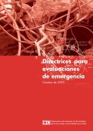
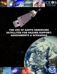
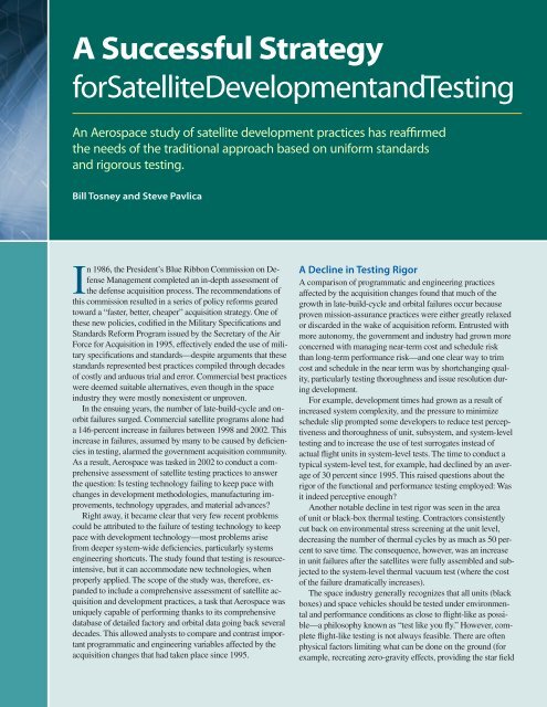
<strong>and</strong> environment <strong>for</strong> testing the attitude control system, providingsolar illumination in vacuum <strong>for</strong> fully extended solar arrays, <strong>and</strong>fitting large systems into a relatively confined vacuum chamber).But even in light of these acknowledged limitations, Aerospacefound an increasing trend away from applying flight-like testingmethodologies where they were previously considered routine,such as in unit <strong>and</strong> subsystem per<strong>for</strong>mance testing <strong>and</strong> softwarecompatibility with hardware in the loop. Similarly, intersegmenttesting between the ground <strong>and</strong> space segments was often eliminatedentirely or greatly reduced in scope.The decision to omit or scale back these tests must be accompaniedby a clear assessment of the attendant risks. Where thereis significant risk exposure by not being able to test appropriately,mitigation strategies can be developed early in the life cycle.Aerospace found these risks were not always well understood, <strong>and</strong>consequently, mitigation strategies were not effectively applied.Aerospace found that best practices <strong>for</strong> flight-like testing hadnot been codified in the industry. There was a general lack ofpractical guidance <strong>for</strong> determining how well or poorly the testingwas conducted. This was particularly true <strong>for</strong> “day in the life” operationaltesting.Traditionally, issues <strong>and</strong> problems uncovered during satellitedevelopment <strong>and</strong> testing would result in design <strong>and</strong> processchanges, which would in turn be scrutinized <strong>for</strong> insights thatvery often improve the development <strong>and</strong> verification process. Asa third-party observer, Aerospace could look across contractorboundaries <strong>and</strong> identify key lessons <strong>and</strong> practices, which couldthen be used to help prioritize the reintroduction of industry-widespecifications <strong>and</strong> st<strong>and</strong>ards. With the cancellation of these st<strong>and</strong>ardsin the mid-1990s, contractors were left on their own to accommodatetechnological changes <strong>and</strong> lessons learned into theirown processes—with variable success.A Leap in ComplexityWhile verification rigor had dropped, overall satellite complexityrose, often exponentially, as a result of advances in electronicstechnology <strong>and</strong> software. Not only were these systems usingmore parts, but the parts themselves were often far more complex,requiring much more stringent design verification <strong>and</strong> qualificationpractices. The greater use of field-programmable gate arrays(FPGAs) <strong>and</strong> application-specific integrated circuits (ASICs),with millions of embedded transistors on a single device, poses aneven greater testing challenge.Not only does increasing complexity pose a challenge tothe verification process, but it also implies an increase in thelikelihood of latent design <strong>and</strong> workmanship defects. Given theincreases in complexity, the corresponding pressures on the verificationprocesses, <strong>and</strong> the increased failure potential, the industry<strong>and</strong> government had embarked on a path of conflicted logic thatresulted in numerous problems that were often not detected untillate in development cycle, or even on orbit.Under acquisition re<strong>for</strong>m, the government did not always specifyrequirements <strong>for</strong> qualifying the parts used in space systems.The manufacturers assumed responsibility <strong>for</strong> piece-part qualification,based on the application <strong>and</strong> the per<strong>for</strong>mance requirementsat the system level. This led to problems <strong>for</strong> several reasons.Acquiring qualified parts had become more difficult as suppliersfocused on commercial markets at the expense of the militaryspace market (which, although relatively small, typically requiresCumulative success rate (percent)Environmental test thoroughness1009080706050TraditionalacquisitionpracticesHigher-riskacquisitionpractices401980 1985 1990 1995 2000Year of launchOut of a sample of more than 450 vehicles manufactured in the United States,those developed using traditional acquisition practices show a consistentlyhigher success rate in the first year of operations. In contrast, vehicles developedusing higher-risk acquisition approaches show markedly lower successrates in the first year of operations.U.S. space asset loss (millions of dollars)100908070605030002500200015001000500Pre - 1995NRO programsPost - 1995L<strong>and</strong>sat 6NOAA 13UFO-1MarsObserverSMC programsAcquisition re<strong>for</strong>m in the national security space arena reduced verificationrigor, as illustrated in the drop in environmental test thoroughness.3 Titan IV’sMilstar/NRO/DSP2 Delta III’sMars Climate Orbiter090 91 92 93 94 95 96 97 98 99YearThis chart shows the value in dollars of U.S. space assets lost during the 1990s.Recent independent studies have shown that reducing technical verificationrigor <strong>and</strong> diminishing the role of independent technical oversight in the developmentof government <strong>and</strong> commercial space systems results in greater problems,as evidenced by higher failure rates <strong>and</strong> cost <strong>and</strong> schedule overruns.
A Return to St<strong>and</strong>ardsThe Air Force Space <strong>and</strong> Missile Systems Center (SMC) <strong>and</strong> the National ReconnaissanceOffice (NRO) have established policies that embrace the use of government, industry, <strong>and</strong>professional society specifications <strong>and</strong> st<strong>and</strong>ards to define program technical baselines.The ef<strong>for</strong>t includes the processes <strong>for</strong> the evaluation, selection, <strong>and</strong> preparation of documents<strong>and</strong> also the processes <strong>and</strong> ground rules <strong>for</strong> implementation as compliance documentsin requests <strong>for</strong> proposals <strong>and</strong> contracts.Aerospace plays an integral role in the review of existing technical st<strong>and</strong>ards, the development<strong>and</strong> publication of new st<strong>and</strong>ards in several engineering disciplines, <strong>and</strong> the implementationof st<strong>and</strong>ards in the acquisition process <strong>for</strong> new systems. Aerospace, NRO, <strong>and</strong>SMC compiled a list of the key st<strong>and</strong>ards <strong>and</strong> have kept the list updated <strong>and</strong> publishedas an Aerospace technical report. Eventually, appropriate documents will be revised <strong>and</strong>reissued as military, industrial, or international st<strong>and</strong>ards. For example, five Aerospacest<strong>and</strong>ards were recently issued as AIAA st<strong>and</strong>ards. In the meantime, Aerospace technicalreports will be used as compliance documents.—Valerie Lang, Joe Meltzer, <strong>and</strong> Jacqueline Unitisstricter parameter control, higher reliability,wider temperature ranges, higher dynamicresponse, radiation hardness, <strong>and</strong> similartraits). In addition, as suppliers switchedfrom a product qualification model to aprocess qualification a model, both primarycontractors <strong>and</strong> government lost insight<strong>and</strong> traceability into parts because supplierswere not required to provide technicaldata <strong>for</strong> qualification <strong>and</strong> traceability. Thegovernment had even less insight, with fewerpeople to track problems <strong>and</strong> less oversightinto manufacturing details.Cost <strong>and</strong> schedule assumed a greater rolein determining which tests <strong>and</strong> analysesshould be used to demonstrate that a devicewas acceptable <strong>and</strong> could meet system requirements.Because of inadequate resources<strong>and</strong> shifting priorities, only new or problematicsuppliers were evaluated or closelymonitored. Verification of compliance wasless disciplined <strong>for</strong> subtier contractors, <strong>and</strong>the prime contractor’s role changed from“right of approval” to “right of rejection.”Flight software complexity had increasedeven more, <strong>and</strong> it is now statistically impossibleto find all possible defects in large softwaresystems. Despite continuing advances,debugging code remains time-consuming:up to 50 percent of a programmer’s timecan be spent debugging code. Furthermore,testing requires a test plan, detailed testprocedures, <strong>and</strong> scripts <strong>for</strong> providing inputto an automated testing tool—an ef<strong>for</strong>t thatcan be just as prone to error as the code itpurports to test. Altogether, complex softwareentails meticulous verification planning<strong>and</strong> software development, a challenge thatis not addressed in development <strong>and</strong> budgetallocations. This underscores the need <strong>for</strong> aReemerging Part SpecificationsBased on a number of recent problems, experience clearly indicates that a more stringent<strong>and</strong> consistent approach to parts, materials, <strong>and</strong> processes—including qualification—mustbe followed. One major objective is to establish a revised st<strong>and</strong>ard that defines the necessarycharacterization, qualification, <strong>and</strong> screening tests <strong>for</strong> microelectronics <strong>and</strong> otherpiece-part commodities (e.g., hybrids, capacitors, resistors, relays, <strong>and</strong> connectors) thatwould clear them <strong>for</strong> use in space applications. This includes government participation toensure that risks are not solely quantified on cost <strong>and</strong> schedule, but life per<strong>for</strong>mance aswell. A rewrite of technical requirements <strong>for</strong> space parts, materials, <strong>and</strong> processes is underway based on previously existing military st<strong>and</strong>ards.rigorous independent assessment of interrelatedsoftware <strong>and</strong> hardware requirementsdevelopment early in the process.Today’s satellite systems involve multipleuser nodes. The increasing number <strong>and</strong> complexityof interfaces led to a rise in interfaceproblems during system-level <strong>and</strong> end-toendtesting among ground, user, <strong>and</strong> spacesegments. These complex interfaces presenta challenge to simulation tools <strong>and</strong> limit theaccuracy of design-margin predictions <strong>and</strong>verification by use of models <strong>and</strong> simulations.A Breakdown inSystems EngineeringIn addition to finding problems with verification<strong>and</strong> testing, the Aerospace study identifiednumerous problems with systems engineeringpractices, including source selection,requirements definition <strong>and</strong> flowdown,system design, engineering requirementverification, manufacturing <strong>and</strong> integrationsupport, <strong>and</strong> scheduling.Data analyzed pointed to a number of systemsengineering deficiencies that resulted innumerous late-build-cycle problems, highlightedby the large increase in design flaws(detected in system-level testing) since 1995.Specific deficiencies include marginalizingthe peer design review process <strong>and</strong> relateddocumentation, descoping preliminary <strong>and</strong>critical design processes, <strong>and</strong> marginalizingthe risk management process. In general,Aerospace found that systems engineeringprocesses were fragmented.Several additional systems engineeringchallenges were also discovered—mostnotably, personnel shortfalls, flawed assumptionsregarding the insertion of commercialproducts in a given design, less emphasison achieving flight-like testing, <strong>and</strong> greateremphasis on cost <strong>and</strong> schedule versus per<strong>for</strong>mance<strong>and</strong> reliability.Spacecraft are extremely complex, <strong>and</strong>program managers have always felt pressureto reduce costs <strong>and</strong> head count. Coupledwith the aging demographics of the spaceindustry work<strong>for</strong>ce, the pressure to minimizestaffing levels had decimated government<strong>and</strong> contractor systems engineering teams—sometimes depleting teams from five or sixdeep to one individual who may not haveenough technical breadth to underst<strong>and</strong> thepotential impact of design issues <strong>and</strong> themany problems that occur during production.This increased the chances that design errorswould go unidentified (<strong>and</strong> uncorrected) untilthey caused a failure. The lack of personnelalso led to a reduction in oversight of the8 • Crosslink Fall 2005
prime contractors by the government <strong>and</strong> ofthe subcontractors by the prime contractors.This increased the likelihood that problemscaused by streamlined design <strong>and</strong> verificationprocess changes at one level would notbe communicated to another.Another common shortfall in systemsengineering <strong>and</strong> verification planning involvedoverly optimistic assumptions aboutthe use of commercial off-the-shelf (COTS)or heritage components. In many cases, thedeveloper assumed that a commercial orheritage product was suitable <strong>for</strong> a new applicationwithout giving sufficient scrutiny tothe intended design use conditions. In reality,commercial or heritage products almostalways require more modifications thanexpected, <strong>and</strong> this adversely affects programschedule. Sometimes, problems with theseproducts were overlooked until they causedcostly failures in ground testing or even onorbit because assumptions regarding thesuitability of the original design to the newapplication’s actual design environment <strong>and</strong>operational scenarios did not pan out.A Get-Well Road MapThe Aerospace study concluded with a seriesof specific recommendations <strong>for</strong> the nationalsecurity space community. In particular, acquisitionmanagers must:• strictly adhere to proven conservativedevelopment practices embodied in bestof-classspecifications <strong>and</strong> st<strong>and</strong>ards;• apply rigorous systems engineering, includingdisciplined peer design reviews<strong>and</strong> clearly traceable verification processes;• emphasize requirements verification <strong>and</strong>testing of all hardware <strong>and</strong> software,focusing on the early development phase<strong>and</strong> lower-level unit design;• apply updated <strong>and</strong> consistent softwaredevelopment <strong>and</strong> verification processes,including meaningful metrics;• instill effective closed-loop design <strong>and</strong>communication processes, with specialattention to new technology insertion,application of COTS components, <strong>and</strong>detailed assessment of operational data<strong>and</strong> lessons learned;• strengthen the qualification <strong>and</strong> verificationof parts, materials, <strong>and</strong> processes;• develop a pyramidal <strong>and</strong> flight-like requirementsverification policy <strong>and</strong> assessthe risk of deviations from this policy;The <strong>Testing</strong> H<strong>and</strong>bookAerospace is developing a comprehensive test <strong>and</strong> evaluation h<strong>and</strong>book that will codifybest practices <strong>for</strong> planning a successful qualification <strong>and</strong> acceptance test strategy. Thish<strong>and</strong>book will deal with the up-front planning <strong>and</strong> production phase as well as orbitalcheckout. The list of guidelines includes lessons learned from the study, such as:• Base schedules on realistic <strong>and</strong> executable models that account <strong>for</strong> system productionmaturity, reasonable levels of integration returns, <strong>and</strong> realistic problem resolution.• Plan a test program that implements a pyramidal requirements verification approach.• Test all high-power electronic units, including RF hardware, in thermal vacuum priorto system-level testing.• Ensure a conservative retest philosophy on all anomalous hardware that accounts <strong>for</strong>fatigue life from prior test exposures.• Develop an EMI/EMC control plan that ensures pertinent EMI/EMC testing at unit<strong>and</strong> appropriate levels of assembly <strong>and</strong> always conduct a system-level EMI/EMC testprior to the thermal vacuum test.• Per<strong>for</strong>m early interface <strong>and</strong> harness compatibility checks on all hardware, preferablyduring development.• Plan <strong>for</strong> intersegment testing at the spacecraft level of assembly <strong>and</strong> include all flighthardware.• Plan <strong>for</strong> a rigorous verification <strong>and</strong> checkout of ground support equipment well inadvance of qualification testing.• Plan <strong>for</strong> a disciplined anomaly tracking <strong>and</strong> resolution process that determines rootcause on all anomalies <strong>and</strong> includes all factory, subcontractor, launch-base, <strong>and</strong>operational anomaly data.• develop a set of engineering h<strong>and</strong>bookswritten from the perspective of the systemprogram office;• manage the product life-cycle data withinthe system program office <strong>and</strong> across theenterprise <strong>and</strong> learn from it.When these practices are applied togetherthroughout development, they have historicallyresulted in successful program acquisitions<strong>and</strong> mission success. Recommendationsfrom major government review panelsare largely consistent with Aerospace conclusionsregarding the proper application ofindustry best practices <strong>and</strong> lessons learned.Moreover, the Aerospace study providesdetailed evidence as to why national security,long-life, space acquisition—<strong>and</strong> morepointedly, the verification process—requiresa different approach than that of a purelycommercial space program. As a result, acquisitionleaders are once again emphasizinga more traditional, proven, <strong>and</strong> disciplinedapproach to engineering space systems.One critical part of such an approachis to ensure that appropriate specifications<strong>and</strong> st<strong>and</strong>ards are applied on a given contract.Specifications <strong>and</strong> st<strong>and</strong>ards arisefrom an often painful <strong>and</strong> costly evolutionaryprocess, <strong>and</strong> in a sense, they <strong>for</strong>m theembodiment of decades of lessons learned<strong>and</strong> best practices. These specifications,st<strong>and</strong>ards, <strong>and</strong> guidelines there<strong>for</strong>e <strong>for</strong>m thecornerstone of traditional best practices thathelp ensure successful execution of a satelliteprogram. Realizing this, Aerospace hasalready helped introduce revised <strong>and</strong> newnational security space st<strong>and</strong>ards <strong>for</strong> spacesystems development, which draw upon thepreviously canceled military st<strong>and</strong>ard withenhancements to bring them up to date withcurrent best practices.Additional best practices related to asuccessful qualification <strong>and</strong> acceptance teststrategy will be defined in a comprehensivetest <strong>and</strong> evaluation h<strong>and</strong>book under developmentat Aerospace. In addition, Aerospace isdeveloping <strong>and</strong> publishing h<strong>and</strong>books thatCrosslink Fall 2005 • 9
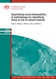
General Design <strong>and</strong> Verification Former CurrentTest Requirements <strong>for</strong> Launch, Upper Stage, <strong>and</strong> Space Vehicles MIL-STD-1540C SMC-TR-04-17 1Test Method St<strong>and</strong>ard <strong>for</strong> Environmental Engineering Considerations <strong>and</strong> Laboratory Tests MIL-STD-810F MIL-STD-810FSoftware <strong>Development</strong> St<strong>and</strong>ard <strong>for</strong> Space Systems MIL-STD-498 Aero. TOR-2004(3909)-3537, Rev. ATest Requirements <strong>for</strong> Ground Equipment <strong>and</strong> Associated Computer Software Supporting SpaceVehiclesMIL-STD-1833MIL-STD-1833Verification Requirements <strong>for</strong> Space Vehicles — Aero. TOR-2005(3901)-4243 2Domain-Specific Design <strong>and</strong> Verification Former CurrentElectromagnetic Compatibility Requirements <strong>for</strong> Space Systems MIL-STD-1541A Aero. TOR-2005(8583)-1Electromagnetic Emissions <strong>and</strong> Susceptibility, Requirements <strong>for</strong> the Control of EMI MIL-STD-461D Aero. TOR-2005(8583)-1Wiring Harness, Space Vehicle, Design <strong>and</strong> <strong>Testing</strong> DoD-W-8357A DoD-W-8357ASpace Battery St<strong>and</strong>ard — Aero. TOR-2004(8583)-5, Rev. 1Qualification <strong>and</strong> Quality Requirements <strong>for</strong> Space-Qualified Solar Panels — AIAA S-112-2005 1Electrical Power Systems, Direct Current, Space Vehicle Design Requirements MIL-STD-1539A Aero. TOR-2005(8583)-2Moving Mechanical Assemblies <strong>for</strong> Space <strong>and</strong> Launch Vehicles MIL-A-83577C AIAA S-114-2005 1Space Systems - Structures Design <strong>and</strong> Test Requirements — AIAA S-110-2005 1Space Systems - Flight Pressurized Systems MIL-STD-1522A Aero. TOR-2003(8583)-2896Space Systems - Metallic Pressure Vessels, Pressurized Structures, <strong>and</strong> Pressure Components MIL-STD-1522A AIAA S-080-1998 1Composite Overwrapped Pressure Vessels MIL-STD-1522A AIAA S-081-2000 1Solid Motor Case Design <strong>and</strong> Test Requirements — Aero. TOR-2003(8583)-2895, Rev. 1Criteria <strong>for</strong> Explosive Systems <strong>and</strong> Devices Used on Space Vehicles DoD-E-83578A AIAA S-113-2005 1Mass Properties Control <strong>for</strong> <strong>Satellite</strong>s, Missiles, <strong>and</strong> Launch Vehicles MIL-STD-1811 Aero. TOR-2004(8583)-3970Part-Level Design <strong>and</strong> Verification Former CurrentQualification <strong>and</strong> Quality St<strong>and</strong>ards <strong>for</strong> Space-Qualified Solar Cells — AIAA S-111-2005 1Electronic Parts, Materials, <strong>and</strong> Processes Control Program Used in Space Programs MIL-STD-1547B Aero. TOR-2004(3909)-3316, Rev. A1. These specifications have been converted to AIAA specifications based on Aerospace technical domain expertise submitted to AIAA technical committees via Aerospace TORs.2. Not included on SMC compliance list. Included with NRO st<strong>and</strong>ards.This table lists the specifications <strong>and</strong> st<strong>and</strong>ards that are being introduced orreintroduced into the national security space acquisition process that relate specificallyto design <strong>and</strong> verification requirements. General design <strong>and</strong> verificationspecifications <strong>and</strong> st<strong>and</strong>ards typically apply to multiple levels of assembly <strong>and</strong>include some discussion of requirements oriented toward the integrated systemlevelarchitecture. Domain-specific st<strong>and</strong>ards are oriented toward environmental,functional, or hardware type testing <strong>and</strong> include requirements <strong>for</strong> batteries, solarpanels, mechanisms, <strong>and</strong> structures. Part-level st<strong>and</strong>ards typically focus on spacerelateditems. For details, see Aero. TOR-2003(8583)-2, Rev. 4, “Systems EngineeringRevitalization Specifications <strong>and</strong> St<strong>and</strong>ards Implementation Plan <strong>and</strong> Status.”provide technical rationale, methodology,<strong>and</strong> tailoring guidance <strong>for</strong> mission assurance<strong>and</strong> space vehicle systems engineering.SummaryThe findings of the Aerospace study arehelping spur national security space initiativesto establish more disciplined systemsengineering, verification, <strong>and</strong> missionassurancestrategies. The assessment of developmentpractice changes, together with ananalysis of on-orbit <strong>and</strong> factory test failures,provided a greater degree of insight into theeffectiveness of the integration <strong>and</strong> testingprocesses, the critical role of the systemsengineering process, <strong>and</strong> the sensitivity ofdesign <strong>and</strong> verification processes to the consequenceof acquisition policy change. Thestudy also shed new light on the relationshipsamong test parameters, levels of assemblytested, test effectiveness, test-related fatigue,<strong>and</strong> the resulting influence on cost, schedule,<strong>and</strong> mission success.<strong>Successful</strong> space systems in the past adheredto a rigorous requirements flowdownprocess that was tied to a comprehensive <strong>and</strong>disciplined verification process that ensuredeach requirement was properly verified <strong>and</strong>traceable to a specific test, analysis, or inspectiondocument. By reemphasizing verification<strong>and</strong> testing at the lowest level <strong>and</strong>testing under flight-like conditions, the governmentis underscoring the importance ofapplying technical rigor in areas where conflicting<strong>and</strong> often marginally successful verificationmethods were being applied becauseof the lack of paradigmatic specifications <strong>and</strong>st<strong>and</strong>ards. Systems engineering <strong>and</strong> missionassurance revitalization initiatives are wellattuned to the urgency to correct the lapsesin the acquisition strategy <strong>and</strong> have consolidatedef<strong>for</strong>ts to accelerate development ofa common <strong>and</strong> technically relevant set ofspecifications, st<strong>and</strong>ards, <strong>and</strong> best practices<strong>for</strong> all national security space programs.10 • Crosslink Fall 2005
Environmental <strong>Testing</strong><strong>for</strong> Launch <strong>and</strong> Space VehiclesSpace systems must endure a physically stressful journey from thelaunchpad to their final destinations. Adequate testing can helpensure they survive the trip.Erwin Perl, Thinh Do, Alan Peterson, <strong>and</strong> John WelchThe structural design of space systems is dictated bythe rigors of the liftoff <strong>and</strong> ascent environments duringlaunch as well as the extreme thermal conditions<strong>and</strong> operational requirements of spacecraft equipment <strong>and</strong>payloads on orbit. At liftoff <strong>and</strong> <strong>for</strong> the next several seconds,the intense sound generated by the propulsion system exertssignificant acoustic pressure on the entire vehicle. This pressureinduces vibration, externally <strong>and</strong> internally, in the space vehiclestructures. In addition, the vehicle experiences intense vibrationsgenerated by engine ignitions, steady-state operation,<strong>and</strong> engine shutdowns as well as sudden transients or “shocks”generated by solid rocket motor jettison, separation of stages<strong>and</strong> fairings, <strong>and</strong> on-orbit deployments of solar arrays <strong>and</strong> payloads.Space vehicles will also experience wide fluctuations intemperature from the time they leave the launchpad to the timethey settle into orbit. Both individually <strong>and</strong> in combination, themechanical environments of pressure, vibration, shock, <strong>and</strong>thermal gradients impose design requirements on many structuralcomponents. Ensuring the survivability of the delicatehardware poses challenges that can be met only by extensivepreflight tests encompassing acoustic, shock, vibration, <strong>and</strong>thermal environments.Environmental testing is per<strong>for</strong>med at varying magnitudes<strong>and</strong> durations to verify the design of space systems <strong>and</strong> toscreen flight hardware <strong>for</strong> quality of workmanship. The firststep in this process is the definition of the maximum expectedenvironments during launch <strong>and</strong> on-orbit operation. Data fromprevious flights <strong>and</strong> ground tests are analyzed to generate predictions<strong>for</strong> a specific mission. These environments are thenflowed down from the space vehicle level to the various subsystems<strong>and</strong> components <strong>for</strong> use as design requirements <strong>and</strong>, later,as test requirements.Aerospace per<strong>for</strong>ms a crucial role <strong>for</strong> the government inensuring that these environments are properly defined <strong>and</strong> thedesign qualification tests <strong>and</strong> the hardware acceptance tests areproperly planned <strong>and</strong> carried out. By reviewing test requirements<strong>and</strong> analysis methodologies, <strong>for</strong> example, Aerospacehelps verify that the results will be accurate <strong>and</strong> meaningful.Reviewing the maximum predicted environments ensures thatspace systems are designed to withst<strong>and</strong> the rigors of flight.Reviewing test plans helps develop perceptive test procedures.Observing the tests builds confidence that they were conductedaccording to specification. Reviewing the test data provides anindependent validation of the results. Archiving <strong>and</strong> catalogingtest data helps test planners ensure that test methods reflect thecurrent state of the art. And of course, by observing test anomalies,Aerospace retains relevant lessons <strong>for</strong> future programs in acontinuous cycle driving toward improved reliability of spacesystems.Acoustic <strong>Testing</strong>A principal source of dynamic loading of space vehicles occursduring liftoff <strong>and</strong> during atmospheric flight at maximumdynamic pressure. It is caused by the intense acoustic pressuregenerated by turbulent mixing of exhaust gases from the mainengines <strong>and</strong> rocket motors with the ambient atmosphere.This acoustic excitation starts when the main engine is ignited<strong>and</strong> lasts approximately 3 to 6 seconds. Ignition producesan exhaust plume that exerts acoustic pressure on the launchpad<strong>and</strong> reflects back to the space vehicle to induce vibration.The magnitude of the exhaust plume <strong>and</strong> the amount of pressureit exerts depends on factors such as engine thrust, exit velocity,engine nozzle diameter, location of structures, <strong>and</strong> ductconfiguration. As the speed of the launch vehicle increases, therelative velocity between the vehicle <strong>and</strong> the ambient atmospheregenerates fluctuating pressures in a turbulent boundarylayer between the exterior surface <strong>and</strong> the atmosphere. As thevehicle traverses the speed of sound, the so-called region oftransonic flight, <strong>and</strong> shortly thereafter, the region of maximumdynamic pressure, the airflow together with aerodynamicshock waves that attach, oscillate, <strong>and</strong> reattach cause acousticexcitations comparable to liftoff, but with different frequencycharacteristics. The sound pressure <strong>and</strong> its induced vibrationare r<strong>and</strong>om in character. The spectra used to assess damage
sometimes used to derive test levels. The predictedacoustic environment is adjusted usingstatistical methods to derive a maximum predictedflight environment. Margin is addedto ensure that the hardware is sufficientlyrobust <strong>and</strong> to account <strong>for</strong> analytical uncertaintiesin the derivation of the environment<strong>and</strong> design of the hardware. A typical qualificationmargin is 6 decibels, or four timesthe energy of the maximum predicted environment.The test lasts at least 1 minute toestablish a duration margin of four times theexposure in flight. Additional test time maybe accumulated depending on the programrequirements. Hardware that is susceptible tothe acoustic-pressure loading are items withlarge surfaces <strong>and</strong> low mass density such ascomposite material solar arrays <strong>and</strong> antennareflectors. These composite structures mayhave design or workmanship deficiencies,which result in bond or material failures.Vibration <strong>Testing</strong>As the launch vehicle lifts off from the st<strong>and</strong><strong>and</strong> throughout powered flight, the vibrationcaused by the operating engines excitesthe vehicle <strong>and</strong> spacecraft structure. Additionalvibration is caused by the fluctuatingacoustic pressure experienced during liftoff,transonic flight, <strong>and</strong> the maximum-dynamicpressurephase of flight.Vibration testing helps demonstrate thathardware can withst<strong>and</strong> these conditions.R<strong>and</strong>om vibration tests are conducted onan electrodynamic vibration machine or“shaker,” which consists of a mounting table<strong>for</strong> the test item rigidly attached to a drivecoilarmature. A control system energizesthe shaker to the desired vibration level.Feedback <strong>for</strong> the control system is providedby a series of accelerometers, which aremounted at the base of the test item at locationsthat correspond to where the launchvehicle adapter would be attached. Twocontrol approaches can be used to provide realisticstructural responses. Most spacecraftvibration tests use response-limiting majorappendageaccelerations to reduce input atdiscrete frequencies so as not to cause unrealisticfailures. For test structures that exhibitdistinct, lightly damped resonances on ashaker, <strong>for</strong>ce limiting is used in conjunctionwith input vibration to control the shaker.In the <strong>for</strong>ce-limiting approach, transducersthat measure the input <strong>for</strong>ce are mounted betweenthe test item <strong>and</strong> the shaker. The goalis to reduce the response of the test item at itsresonant frequencies on the shaker to replicatethe response at the combined system atSound pressure levels(decibels)140130120110100908010 100 1000 10,0001/3 Octave frequency (hertz)Maximum predicted acoustic level <strong>for</strong> liftoffMaximum predicted acoustic level <strong>for</strong> transonic/max QMaximum workmanship requirement <strong>for</strong> acoustic testTypical acoustic test level is a smooth envelope plus 6 dB marginthe resonant frequencies that would exist inthe flight-mounting configuration.As in the case of acoustic testing, heritageflight <strong>and</strong> test data are used to predict vibrationtest levels, <strong>and</strong> analytical methods aresometimes used to develop transfer functionsto scale heritage data to new hardware configurations.In most cases, the predicted environmentsare verified later with system-levelacoustic tests <strong>and</strong> rocket engine static firetests. As with acoustic testing, a 6-decibelmargin is typically added to the maximumpredicted environment. Structural failures ofpiece parts, unit assemblies, <strong>and</strong> secondary<strong>and</strong> primary space vehicle structures can <strong>and</strong>do occur from vibration-induced stress <strong>and</strong>material fatigue. Failures of inadequately designedor poorly manufactured or assembledstructural interfaces are commonly revealed.Aerospace personnel, using predictivesoftware, provide analysis confirmation <strong>for</strong>optimal instrumentation <strong>for</strong> vibration testing.Aerospace confirms hardware test perceptiveness<strong>and</strong> effectiveness with analysis,Power spectral density1.000000.100000.010000.001000.00010Typical acoustic test levelused to simulate thelaunch vehicle environment.The spectrum isdivided into 1/3-octaveb<strong>and</strong>s, <strong>and</strong> the soundpressure level is specified<strong>for</strong> each b<strong>and</strong> in decibels.The frequency range istypically from 30 to 10,000hertz.testing experience, <strong>and</strong> consideration ofinterface constraints.Shock <strong>Testing</strong>Stage, fairing, <strong>and</strong> vehicle separations areoften accomplished by means of pyrotechnicdevices such as explosive bolts, separationnuts, bolt cutters, exp<strong>and</strong>ing-tube separationsystems, clamp b<strong>and</strong>s, ordnance thrusters,<strong>and</strong> pressurized bellows. When activated,these devices produce powerful shocks thatcan damage equipment <strong>and</strong> structures. Thecharacteristics of these shocks depend onthe particular separation mechanism, butthe energy spectrum is usually concentratedat or above 500 hertz <strong>and</strong> is measured in afrequency range of 100 to 10,000 hertz. Atypical shock response spectrum plot is usedto gauge the damage potential of a givenseparation event.Separations or deployments generatebrief impulsive loads even if no pyrotechnicdevices are used. Nonexplosive initiatorsmay produce significant shock levels simply0.0000110 100 1000Frequency (hertz)10,000Maximum predicted vibration level <strong>for</strong> liftoffMaximum predicted vibration level <strong>for</strong> transonic/max QMaximum workmanship requirement <strong>for</strong> vibration testTypical vibration test level is a smooth envelope plus 6 dB marginTypical vibration testlevel used to simulatethe launch vehicle environment.A 6-decibelqualification margin istypically added to themaximum predictedenvironment to ensurethat the hardware is sufficientlyrobust.Crosslink Fall 2005 • 13
Measured accelerationtime histories are usedto derive shock test requirements.Shock levels are specifiedas shock responsespectra defined over afrequency range. Theshock response spectrauses the responseof single-degree-offreedomoscillators,computed in 1/6 octaveb<strong>and</strong>s to convertthe time history to thefrequency domain.300200100–100–200through the release of structural strain. Experiencehas shown that shock can induce ahard or intermittent failure or exacerbate alatent defect. Commonly encountered hardwarefailures include relay transfer, crackingof parts, dislodging of contaminants, <strong>and</strong>cracking of solder at circuit-board interfaces.Unit-level shock tests are accomplishedusing one of several methods, which generallyentail securing the component to afixture that is then subjected to impact. This“ringing plate” approach has provided thebest practicable simulation of unit exposureto shock. In addition, vibration shakers areused in some applications to impart a transientshock. Shock testing is typically notTemperatureFFHS, FFCS, FF0–300552.50 552.55 552.60 552.65 552.70 552.75 552.8010 310 210 1 10 310 2 10 4AFAFAFCS, FFper<strong>for</strong>med as a unit workmanship screen,but is deferred to the system level <strong>for</strong> greaterdetection of functional defects. System-levelshock tests usually activate the separationor deployment systems, providing a directsimulation of the mission event. Thus, theydo not include any amplitude margin. Testfixtures are used to support hardware thathas been deployed or separated to preventsubsequent contact or damage. System-levelshock tests provide an excellent opportunityto measure shocks incident on componentsthroughout the space vehicle.Accurate prediction of high-frequencyshock levels, such as those associated withexplosive ordnance, remains an elusive goal.HS, FFTimeFFA typical thermal cyclingor thermal vacuumtest profile. Theprofile shows temperaturehistory <strong>and</strong> alwaysstarts <strong>and</strong> ends at roomtemperature. Hot starts(HS), cold starts (CS),full functional tests (FF),<strong>and</strong> abbreviated functionaltests (AF) are per<strong>for</strong>medat temperatureplateaus.There<strong>for</strong>e, it is important that the shock environmentbe assessed during the developmentphase of the program through both analysis<strong>and</strong> test simulations. Shock analysis includesconsideration of the source amplitudes,durations, transmission paths, path materials,<strong>and</strong> path discontinuities. <strong>Development</strong>tests employ an accurate replica of the flightstructure with all significant constituentssimulated. Deployed hardware is <strong>for</strong>ced tophysically separate at least a small amountto provide realistic shock transmission paths.When practical, a shock-producing event isrepeated several times to permit meaningfulstatistical evaluation of the resultingdata. Qualification margins at the unit levelare typically 6 decibels on amplitude <strong>and</strong>twice the number of flight activations. At thesystem level, it is generally impractical toimpose an amplitude qualification margin;however, a margin of two or three activationsis imposed. Aerospace provides expertise <strong>for</strong>the prediction of test levels <strong>and</strong> the configurationof the hardware interfaces to achievean effective test.Thermal <strong>Testing</strong>Launch vehicles <strong>and</strong> spacecraft must endurea wide range of temperatures associated withliftoff <strong>and</strong> ascent through the atmosphere,direct impingement of solar radiation, <strong>and</strong>travel through the extreme temperatures ofspace. The thermal environment is generallyconsidered the most stressful operating environment<strong>for</strong> hardware in terms of fatigue,<strong>and</strong> it has a direct bearing on unit reliability.For example, the use of materials with differingcoefficients of thermal expansionhas resulted in unsuccessful deploymentsof mechanical assemblies <strong>and</strong> payloads.Outgassing increases significantly withtemperature, <strong>and</strong> the resulting contaminantswill more readily adhere <strong>and</strong> chemicallybond to colder surfaces. Electronic parts areespecially sensitive to the thermal conditions<strong>and</strong> are subject to problems such as cracks,delamination, bond defects, discoloration,per<strong>for</strong>mance drift, coating damage, <strong>and</strong>solder-joint failure.Thermal testing is used to screen outcomponents with physical flaws <strong>and</strong> demonstratethat a device can activate <strong>and</strong> operatein extreme <strong>and</strong> changing temperatures. Thefour most common thermal tests are thermalcycling, thermal vacuum testing, thermalbalance testing, <strong>and</strong> burn-in testing. Thermalcycling subjects the test article to a numberof cycles at hot <strong>and</strong> cold temperatures in anambient-air or gaseous-nitrogen environ-14 • Crosslink Fall 2005
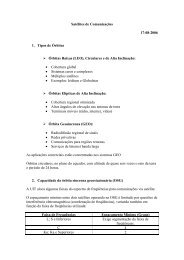
ment; convection enables relatively rapidcycling between hot <strong>and</strong> cold levels. Thermalvacuum testing does the same thing, but in avacuum chamber; cycles are slower, but themethod provides the most realistic simulationof flight conditions. In thermal balancetesting, also conducted in vacuum, dedicatedtest phases that simulate flight conditions areused to obtain steady-state temperature datathat are then compared to model predictions.This allows verification of the thermal controlsubsystem <strong>and</strong> gathering of data <strong>for</strong> correlationwith thermal analytic models. Burnintests are typically part of thermal cycletests; additional test time is allotted, <strong>and</strong> theitem is made to operate while the temperatureis cycled or held at an elevated level.For electronic units, the test temperaturerange <strong>and</strong> the number of test cycles have thegreatest impact on test effectiveness. Otherimportant parameters include dwell time atextreme temperatures, whether the unit isoperational, <strong>and</strong> the rate of change betweenhot <strong>and</strong> cold plateaus. For mechanical assemblies,these same parameters are important,along with simulation of thermal spatialgradients <strong>and</strong> transient thermal conditions.Thermal test specifications are based primarilyon test objectives. At the unit level,the emphasis is on part screening, whichis best achieved through thermal cycle <strong>and</strong>burn-in testing. Temperature ranges aremore severe than would be encountered inflight, which allows problems to be isolatedquickly. Also, individual components areeasier to fix than finished assemblies.At the payload, subsystem, <strong>and</strong> spacevehicle levels, the emphasis shifts towardper<strong>for</strong>mance verification. At higher levels ofShock response spectra10,00010001001010.1100 1000Frequency (hertz)10,000Maximum predicted shock level <strong>for</strong> fairing separationMaximum predicted shock level <strong>for</strong> stage separationMaximum predicted shock level <strong>for</strong> spacecraft separationTypical shock test level is a smooth envelope plus 6 dB marginassembly in flight-like conditions, end-toendper<strong>for</strong>mance capabilities can be demonstrated,subsystems <strong>and</strong> their interfacescan be verified, <strong>and</strong> flightworthiness requirementscan be met. On the other h<strong>and</strong>, at thehigher levels of assembly, it is difficult (if notimpossible) to achieve wide test temperatureranges, so part screening is less effective.At the unit, subsystem, <strong>and</strong> vehicle levels,Aerospace thermal engineers work with thecontractor in developing test plans that provethe design, workmanship, <strong>and</strong> flightworthinessof the test article. Temperature rangesare selected that will adequately screen or accuratelysimulate mission conditions, <strong>and</strong> theproper number of hot <strong>and</strong> cold test plateausare specified to adequately cycle the testequipment. Aerospace will provide expertiseduring the test to protect the space hardwarein the test environment, resolve test issues<strong>and</strong> concerns, <strong>and</strong> investigate test articlediscrepancies. The reason, of course, is thatTypical test level usedto simulate the shockenvironment. Qualificationmargins at theunit level are typically6 decibels.identifying <strong>and</strong> correcting problems in thermaltesting significantly increases confidencein mission success.ConclusionSince the first satellite launch in 1957, morethan 600 space vehicles have been launchedthrough severe <strong>and</strong> sometimes unknown environments.Even with extensive experience<strong>and</strong> a wealth of historical data to consult,mission planners face a difficult task in ensuringthat critical hardware reaches spacesafely. Every new component, new process,<strong>and</strong> new technology introduces uncertaintiesthat can only be resolved through rigorous<strong>and</strong> methodical testing. As an independentobserver of the testing process, Aerospacehelps instill confidence that environmentalrequirements have been adequately defined<strong>and</strong> the corresponding tests have been properlyplanned <strong>and</strong> executed to generate useful<strong>and</strong> reliable results.Left: A spacecraft is placed in the acoustic chamber <strong>and</strong> is ready <strong>for</strong> testing. Air horns at the corners of thechamber generate a prescribed sound pressure into the confined space <strong>and</strong> onto the spacecraft. Microphoneslocated around the spacecraft are used to monitor <strong>and</strong> control the pressure levels. Middle: The sudden separationof the payload fairing is used to expose spacecraft components to the shock environment expected inflight. Right: Space instrument placed on an electrodynamically controlled slip table <strong>for</strong> vibration testing. Thecontrol accelerometers are mounted at the base of the test fixture at a location that represents the interface tothe launch vehicle adapter. Accelerometers mounted on the test specimen measure the dynamic responses.Crosslink Fall 2005 • 15
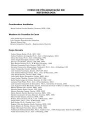
Software <strong>Testing</strong>in Space ProgramsAs space-system software grows in size <strong>and</strong> complexity, adequate testingbecomes more difficult—<strong>and</strong> more critical.Myron Hecht <strong>and</strong> Douglas BuettnerPhoto courtesy of European Space Agency; Ada code from http://www-aix.gsi.de/~giese/swr/ariane5.html...declarevertical_veloc_sensor: float;horizontal_veloc_sensor: float;vertical_veloc_bias: integer;horizontal_veloc_bias: integer;...begindeclarepragma suppress(numeric_error, horizontal_veloc_bias);beginsensor_get(vertical_veloc_sensor);sensor_get(horizontal_veloc_sensor);vertical_veloc_bias := integer(vertical_veloc_sensor);horizontal_veloc_bias := integer(horizontal_veloc_sensor);...exceptionwhen numeric_error => calculate_vertical_veloc();when others => use_irs1();end;end irs2;The Ariane 5 launch vehicle failed on its maiden flight in June1996. About 40 seconds after liftoff, a software bug in theflight controller made the rocket veer off course, leading to itsdestruction via ground comm<strong>and</strong>. Ariane 5 reused softwarefrom Ariane 4 without proper testing. Contributing to themishap, run-time range checking had been turned off becauseof processor limitations. Also, the backup channel had failedmilliseconds earlier because of the same coding defect.Failures attributed to software defects are becoming increasinglyvisible in space systems. Recent newsworthy examples include thefailure of the Mars rover Spirit to execute any task that requestedmemory from the flight computer; the unanticipated descent of the MarsClimate Orbiter into the Martian atmosphere, ultimately traced to a unitconversion defect in a navigation system; <strong>and</strong> the crash of the Mars PolarL<strong>and</strong>er onto the Martian surface after a premature shutdown of its descentengines. In 1996, the first launch of the Ariane 5 booster ended with aspectacular crash off the coast of French Guiana. The cause was traced toa variable overflow that affected software running in both channels of itsdual redundant inertial reference system. Earlier this year, the EuropeanSpace Agency’s Huygens probe successfully beamed back only half ofits image data. The other half was lost because of a single missing line ofcode.In the period from 1998 to 2000, nearly half of all observed spacecraftanomalies were related to software. Anomalies, less severe than failures,have been occurring with increasing frequency on U.S. national securityspace vehicles. One reason is that space-system software has been growingmore complex to meet greater functional dem<strong>and</strong>s. Another reason isthat software quality is inherently difficult to determine. The challenge indeveloping the next generation of national security space vehicles will beto ensure reliability despite increasing software size <strong>and</strong> complexity. Softwaretesting is an important factor in meeting this challenge.Types of Software <strong>Testing</strong>Software testing methods generally fall into two categories: “black box”<strong>and</strong> “white box” (while some authors also identify a third category, the“ticking box,” which involves not doing any testing).Black-box methods disregard the software’s internal structure <strong>and</strong>implementation. The test data, completion criteria, <strong>and</strong> procedures aredeveloped solely to test whether the system meets requirements, withoutconsideration of how the software is coded. Black-box testing is used at alllevels of testing <strong>and</strong> is particularly applicable at higher levels of integration,where the underlying components are no longer visible.White-box testing, on the other h<strong>and</strong>, does account <strong>for</strong> the internalsoftware structure in the <strong>for</strong>mulation of test cases <strong>and</strong> completion criteria.The most common types of white-box testing include branch testing,
which runs through every instruction in eachconditional statement in a program, <strong>and</strong> pathtesting, which runs through every set of conditionalstatements or branches. White-boxtesting is typically conducted at the unit level(i.e., the smallest testable component of software)<strong>and</strong> at the unit integration level.Both methods would typically includesome sort of nominal testing, in which testcases are designed to mimic normal operation,<strong>and</strong> negative testing, in which test casesare selected to try <strong>and</strong> “break” the program.For example, the software might be runusing input values of the correct type <strong>and</strong>within the expected range to verify con<strong>for</strong>mancewith nominal requirements. It mightalso be run using input values <strong>and</strong> data ratesbeyond expected ranges to check failsafe <strong>and</strong>recovery capabilities.The <strong>Testing</strong> ProgramWhite-box <strong>and</strong> black-box testing is per<strong>for</strong>medwithin the context of an overallsoftware test program that starts during therequirements phase <strong>and</strong> continues throughproduct release <strong>and</strong> maintenance. Softwaredevelopment st<strong>and</strong>ards provide a basis <strong>for</strong>defining the activities of the overall test program.Although the use of such st<strong>and</strong>ardsdeclined in the 1990s, they are now increasinglyrecognized as an important way tohelp ensure software quality despite risingcomplexity.For example, the National ReconnaissanceOffice (NRO) <strong>and</strong> the Air Force Space<strong>and</strong> Missile Systems Center (SMC) recentlyasked Aerospace to recommend a set ofsoftware development st<strong>and</strong>ards to be usedas compliance documents on NRO <strong>and</strong> SMCcontracts. Aerospace assisted with a detailedsurvey of existing life-cycle st<strong>and</strong>ards <strong>and</strong>recommended the use of MIL-STD-498 orits commercial equivalent, J-STD-016-1995.However, MIL-STD-498 was canceled inthe mid-1990s, <strong>and</strong> J-STD-016 is no longerbeing maintained by the technical organizationsthat produced it. There<strong>for</strong>e, SMC<strong>and</strong> NRO felt that a new software st<strong>and</strong>ardshould be developed.Aerospace helped analyze MIL-STD-498 in greater detail <strong>and</strong> identified waysto modernize J-STD-016. Based on thisef<strong>for</strong>t, Aerospace prepared a new st<strong>and</strong>ard,published as Aerospace Report No. TOR-2004(3909)-3537, “Software <strong>Development</strong>St<strong>and</strong>ard <strong>for</strong> Space Systems.” It uses MIL-STD-498 as a foundation, but incorporatesadditional requirements from J-STD-016.It also adds exit criteria <strong>for</strong> various levelsOn-orbit anomalies per vehicle8765432102vehiclesYear Ranges1981 - 19951986 - 19901991 - 19951996 - 20002001 - 6/0310vehicles12vehicles1985 1990 1995 2000 >20005-Year Incrementsof software testing <strong>and</strong> requirements thatbring the st<strong>and</strong>ard up to date with modernterminology <strong>and</strong> best practices in softwaredevelopment.Many software development st<strong>and</strong>ards,including MIL-STD-498 <strong>and</strong> the Aerospacerevision, set <strong>for</strong>th requirements <strong>for</strong> threemajor activities of software testing: planning,definition, <strong>and</strong> execution.Software test planning addresses all levelsof coding <strong>and</strong> integration, from the highestlevelsoftware package down to the lowestlevelsoftware units. The results are documentedin a software test plan. Lower-leveltest plans are independently created if thesoftware’s size <strong>and</strong> complexity warrants it.The software test plan enables the programmanager to assess the adequacy of test planning<strong>for</strong> each of the software items <strong>and</strong> <strong>for</strong>the software system qualification testing. Inaddition, the software test plan lists the issuesthat should be considered in the developmentof the software test definition.In the test definition stage, the test preparations,test cases, <strong>and</strong> test procedures areall described <strong>and</strong> documented. This mayinvolve a significant design <strong>and</strong> developmentef<strong>for</strong>t—in some cases, equal to or exceedingthat of the software itself. This is particularlytrue <strong>for</strong> software item qualification testing,in which individual software componentsare accepted <strong>for</strong> integration into the system.Software item qualification testing is criticallydependent on the accuracy of the softwaretest definition.Once the test definition has been completed,it is possible to actually run the tests<strong>and</strong> record the results in the software testreport. As part of this process, the test organizationshould emphasize findings <strong>and</strong> observationsof anomalies. The software test reportcan also include suggestions <strong>for</strong> furthertesting based on the limitations of the testequipment or limitations arising from budgetor time constraints. The software test report5vehicles3 vehiclesAnomaly trend attributedto software in five-yearincrements from the firstthree years of the spacecraft’soperation usingavailable failure data froma wide range of satellitecategories.documents the test results <strong>and</strong> includes accumulatedtest analyses, results, summaries,deviations from dry runs, <strong>and</strong> metrics.Limitations of Software <strong>Testing</strong>Despite its obvious importance, softwaretesting is only a partial solution to creatingreliable software. In a sense, the purpose oftesting is to show that a program has bugs.Thus, while it can provide a means to find<strong>and</strong> fix defects, it cannot by itself provide anassurance of failure-free operations. Softwaretesting must be pursued in conjunctionwith other appropriate practices in systemsengineering, requirements definition, <strong>and</strong>software development (such as inspection,the use of automated development aids, staticsource code <strong>and</strong> design analysis, <strong>and</strong> peerreview).A significant limitation is that softwaretesting cannot occur until after the code iswritten—about halfway or more throughproject development. The cost of fixingerrors rises dramatically as the project progressesbecause more deliverables are affected.For example, requirements errors cost10 times more to fix in the code phase than inthe requirements phase. Methods of softwareverification other than testing (under thebroad categories of inspection, analysis, ordemonstration) must be used to catch errorsin the earlier phases of design.A related limitation is that the effectivenessof a testing program is no better than therequirements on which it is based. Aerospaceanalysis has shown that the generation ofsoftware requirements is a major source oferrors in system development. Specific challengesinclude poorly stated requirements,changing or “creeping” requirements, <strong>and</strong>nonfunctional requirements. A study ofrequirements-originated software failuresshowed that roughly half resulted frompoorly written, ambiguous, unclear, <strong>and</strong>incorrect requirements. The rest came from32 • Crosslink Fall 2005
Method <strong>and</strong> Description Objective Test Type Applicable LevelScenario-based (also called thread) testing: <strong>Testing</strong> using data basedon usage scenarios, e.g., simulation of the mission.Requirements-based testing: <strong>Testing</strong> to assess the con<strong>for</strong>mance of thesoftware with requirements.Nominal testing: <strong>Testing</strong> using input values within the expected range<strong>and</strong> of the correct type.Stress testing (a type of negative testing): <strong>Testing</strong> with simulated levelsbeyond normal workloads, or starving the software of the computationalresources needed <strong>for</strong> the workload; also called workload testing(usually run concurrently with endurance tests).Robustness testing (a type of negative testing): <strong>Testing</strong> with values,data rates, operator inputs, <strong>and</strong> workloads outside expected ranges.Boundary-value testing (a type of negative testing): <strong>Testing</strong> the softwarewith data at <strong>and</strong> immediately outside expected value ranges.Extreme-value testing (a type of negative testing): <strong>Testing</strong> <strong>for</strong> largevalues, small values, <strong>and</strong> the value zero.R<strong>and</strong>om testing: <strong>Testing</strong> the software using input data r<strong>and</strong>omly selectedfrom the operational profile probability distribution.Fault-injection testing: <strong>Testing</strong> on the nominal baseline source code<strong>and</strong> r<strong>and</strong>omly altered versions of the source (white box) or object code(black box).Branch testing: <strong>Testing</strong> using test cases selected to test each branch atleast once.Path testing: <strong>Testing</strong> using test cases selected to test each path (i.e.,feasible set of branches) at least once. Also called flow-graph testing.Modified-condition decision coverage: Every point of entry <strong>and</strong> exitin the program has been invoked at least once, every condition in adecision in the program has taken all possible outcomes at least once,every decision in the program has taken all possible outcomes at leastonce, <strong>and</strong> each condition in a decision has been shown to independentlyaffect that decision’s outcome.Typical black-box <strong>and</strong> white-box test methods.Assess overall con<strong>for</strong>mance <strong>and</strong>dependability in nominal usage.Determine whether the softwaremeets specific requirements.Verify con<strong>for</strong>mance with nominalrequirements.Measure capacity <strong>and</strong> throughput;evaluate system behavior underheavy loads <strong>and</strong> anomalous conditionsto determine workload levelsat which system degrades or fails.Challenge or “break” the systemwith the objective of testing failsafe <strong>and</strong> recovery capabilities.Test error detection <strong>and</strong> exceptionh<strong>and</strong>ling behavior of software withanticipated exception conditions.Same as boundary-value testing.Assess overall stability, reliability,<strong>and</strong> con<strong>for</strong>mance with requirements.Assess failure behavior, ensure thatsystem properly responds to componentfailures.Test correctness of code to thelevel of branches.Test correctness of code to thelevel of paths.Test <strong>for</strong> safety-critical softwarewhere a failure would probably oralmost inevitably result in a lossof life.Black box.Black box.Black box.Black box.Black <strong>and</strong>white box.Black <strong>and</strong>white box.Black <strong>and</strong>white box.Black box.Black <strong>and</strong>white box.White box.White box.White box.Integrated software <strong>and</strong>system.All levels at which requirementsare defined.All.Integrated software <strong>and</strong>system.All.Unit, software subsystem.Unit, software subsystem.Integrated system.Integrated software.Software unit.Software unit.Software unit (assemblycode created by compilerunder some circumstances).requirements that were completely omitted.Most problems introduced into software canbe traced directly to requirements flaws.An additional limitation is the difficulty—<strong>and</strong> hence the time, cost, <strong>and</strong> ef<strong>for</strong>t—ofsoftware testing. Ideally, a software systemcould be exhaustively tested <strong>and</strong> therebyproven correct. However, this is impossible<strong>for</strong> all but the simplest systems. Manyspace-system software applications are socomplex, <strong>and</strong> run in such an interdependentenvironment, that complete testing can neverbe achieved. Instead, program managersmust prioritize their testing objectives <strong>and</strong>optimize their testing procedures to ensurethat the most important tests are completed.Skill in risk analysis is there<strong>for</strong>e essential<strong>for</strong> establishing an appropriate test coverageobjective—usually stated as a proportion ofthe requirements, input data, instructions, orprogram paths tested (e.g., testing is completewhen the tests addressing 100 percentfunctional coverage of the system have allexecuted successfully).Proper selection of input data can increasethe testing efficiency by either increasingthe error-detection effectiveness or reducingthe number of test cases needed to achieve agiven test coverage objective. For example,tests can be partitioned to exercise the samecode using only one representative case. Thenumber of test cases <strong>for</strong> each class of failurebehavior can be limited. If software inspectionis used in the development process, thedistribution of defects (by category) detectedby inspection can be used to drive the distributionof test data. The amount of coupling(intermodule referencing of variablesor subroutines) can be used to focus testcases—particularly if a significant amount ofsoftware changes have been made. Test casescan also be concentrated on areas exhibitingan abnormally high number of failures. Testcase input data can also be selected using a“design of experiments” approach.How Much <strong>Testing</strong> is Enough?Considering that complete test coverage isgenerally not possible, project managersface a difficult question in deciding when tostop testing. In practice, this decision is oftenbased not on specific <strong>and</strong> quantifiable goalsbut on deadlines, budgets, or completion ofan arbitrary number of test runs.For national security space systems, a bettercriterion would be the point at which thesoftware reaches an acceptable level of reliability,as measured in time between failures.This method, often referred to as softwarereliability engineering, is a recommendedpractice by the American Institute of Aeronautics<strong>and</strong> Astronautics (AIAA).Crosslink Fall 2005 • 33
The fundamental premise of software reliabilityengineering is that the rate at whichsoftware defects are found <strong>and</strong> removed canbe described mathematically <strong>and</strong> there<strong>for</strong>epredicted. These discovery <strong>and</strong> removal ratescan be constant or variable, depending onthe models used. If the testing environmentsimulates the operational environment, thenfailure rates observed at any point in the testwould be similar to the operational failurerates, <strong>and</strong> the model would enable a predictionof the future failure rate as the testingprogram proceeded. They would there<strong>for</strong>eprovide an ability to predict the software’sfuture reliability.Software reliability engineering originatedin the 1970s <strong>and</strong> has been the subjectof extensive research since that time. Toolshave been developed to fit various models totest data to enable determination of the bestfit <strong>and</strong> subsequent extrapolation to enableprediction. Software reliability engineeringprovides a cost-effective method to determinewhen to stop testing. Cost typicallyranges from 0.1 to 3.0 percent of project developmentcosts.To help improve the accuracy <strong>and</strong> valueof these prediction models, Aerospace hasbeen working to develop a database schema<strong>for</strong> software reliability data. The project,Space Systems Mission Assurance via SoftwareReliability Monitoring, will correlatesoftware life-cycle engineering practices(including test) with the reliability measuredfrom deployed space-systems software. Aneventual goal is to provide a risk-assessmenttool <strong>for</strong> program managers that will allowthem to compare key software life-cyclemetrics <strong>and</strong> test practices from their programto historical data from other programs. Thedatabase is being designed to support threetypes of analyses: exploratory, quantitative,<strong>and</strong> qualitative. Exploratory analysis wouldallow users to investigate relationships thatcould be used to predict software <strong>and</strong> systemreliability based on project, structural, <strong>and</strong>test program attributes. Quantitative analysiswould allow users to extract event data topredict software reliability. Qualitative analysiswould allow users to address questionssuch as what are the major failure causes, effects,or developmental problems.Safety-Critical SoftwareAlthough software reliability engineeringcan benefit many types of software, specialconsiderations must be made <strong>for</strong> safetycriticalsoftware—the failure of which canlead to death, major injury, or extensiveActivitiesSoftware Test PlanningSoftware TestDescriptionSoftware Test Execution<strong>and</strong> ReportingKey software test issues.Key Issuesproperty damage. A good example is thesoftware supporting the Global PositioningSystem (GPS). An undetected failure inthe navigation signal from any of the GPSsatellites might result in an aircraft receivingmisleading in<strong>for</strong>mation on its position oraltitude, thereby exposing its occupants to ahigh risk of a crash l<strong>and</strong>ing. Thus, the softwarecomponents involved in integrity monitoring,which would detect <strong>and</strong> announce anavigation signal failure, must receive specialscrutiny.Test organization, including personnel, responsibilities, discrepancy reportingrequirements, <strong>and</strong> release processes.Budget <strong>and</strong> schedule requirements, test schedule estimates, milestones, <strong>and</strong>deliverables.Plans <strong>for</strong> maintaining <strong>and</strong> updating test plans, test cases, test environment, <strong>and</strong>automated tools through the life cycle.<strong>Strategy</strong> <strong>for</strong> changes in the requirements <strong>and</strong> software items (in particular, regressiontesting).<strong>Testing</strong> of commercial or nondevelopmental item software.Particular equipment, procedures, methods, or data necessary to address the requirementsof the specific program <strong>for</strong> which the plans are developed.Completion criteria.Software requirements addressed by the test.Test driver environment (interfacing hardware, software, communications, etc.).Automated testing tools (record/playback tools, coverage analyzers, test tracking,etc.).Test completion criteria.Means of evaluating correctness of results (test method).Test tracking, logging, <strong>and</strong> archiving processes.Test setup steps.Metrics <strong>for</strong> the reporting of results.Retest criteria.Test input data requirements.Evaluation of test case data to assess success or failure.Procedures to undertake when an anomaly occurs to capture the circumstancessurrounding the failure.Overall assessment of software tested.Identification of deficiencies.Problem reports filed.Test environment version, constraints, etc.Recommendations <strong>for</strong> improvement.Deviations from procedures <strong>for</strong> each test case.Details <strong>for</strong> analysis required to document the pass/fail conclusion.Who executed the tests.Who witnessed the tests.Where the test results are archived.When were the test cases executed.Aerospace is supporting the GPS programoffice in producing high-integrity software<strong>for</strong> the next-generation GPS constellation.For safety-critical software, testing is partof a process of analysis, documentation,<strong>and</strong> traceability that starts at the beginningof the project <strong>and</strong> continues throughout thesystem lifetime. For example, when requirementsare being <strong>for</strong>mulated, a preliminaryor functional hazard analysis is per<strong>for</strong>med toidentify major hazards <strong>and</strong> develop mitigationstrategies. At the design phase, two more34 • Crosslink Fall 2005
system-safety analyses are per<strong>for</strong>med todetermine the safety impact of the softwarecomponents in their normal <strong>and</strong> failed states.For critical software components, verification,testing, <strong>and</strong> documentation must be per<strong>for</strong>medintensively. For example, in aviationapplications, the RTCA DO 178B st<strong>and</strong>ardprovides <strong>for</strong> testing of all combinations ofconditions in branches in such software.Even intensive testing has the same limitationdiscussed earlier: it can only prove thepresence of defects in software, not their absence.Thus, Aerospace <strong>and</strong> other organizationsare researching methods that use mathematicaltechniques to prove the correctnessof the specification, the verification test suite,<strong>and</strong> the automatic code generators that createthe software. The goal is to use <strong>for</strong>malmethods <strong>and</strong> testing together to significantlydecrease development time while producingdependable software.ConclusionWith the addition of progressively more softwarefunctionality in both space <strong>and</strong> groundsegments, program managers will facetougher challenges in ensuring software reliability.Software testing ef<strong>for</strong>ts will requirebetter analytical methods <strong>and</strong> oversight approachesto meet the greater dem<strong>and</strong> withoutadversely affecting budgets <strong>and</strong> schedules.By participating in software test planning<strong>and</strong> data analysis, reviewing softwaredevelopment st<strong>and</strong>ards <strong>and</strong> practices, <strong>and</strong> byper<strong>for</strong>ming research on software reliability,Aerospace is helping to make the softwaretesting process more efficient <strong>and</strong> effective.The results of this research should augmentsoftware-intensive system acquisition practiceswith tools to help program managersensure mission success.Further ReadingAerospace Report No. TOR-2004(3909)-3537,“Software <strong>Development</strong> St<strong>and</strong>ard <strong>for</strong> Space Systems.”(The Aerospace Corporation, El Segundo,CA, 2004)AIAA/ANSI R-013-1992, Recommended Practice:Software Reliability, American Institute ofAeronautics <strong>and</strong> Astronautics (Reston, VA).P. Cheng, “Ground Software Errors Can Cause<strong>Satellite</strong>s to Fail too—Lessons Learned,”Ground Systems Architecture Workshop (ManhattanBeach, CA, March 4, 2003); availablefrom http://sunset.usc.edu/gsaw/gsaw2003/agenda03.html (last visited April 29, 2005).G. Durrieu, C. Seguin, V. Wiels, <strong>and</strong> O. Laurent,“Test Case Generation Guided by a CoverageCriterion on Formal Specification,” IEEE InternationalSymposium on Software ReliabilityEngineering (ISSRE, Nov. 2004).120100Total Failures8060402000 5 10 15 20 25 30 35 40 45 50Test Interval25020015010050NHPP Mean Value Function=m(t)=a(l -e-bt)a=Expected cumulative number of errorsb=Error detection rateRaw DataNHPP (intervals)Schneidewind: all0 0 5001000Test Interval NumberJ. T. Harding, “Using Inspection Data to ForecastTest Defects,” Crosstalk (May 1998);available at http://www.stsc.hill.af.mil/crosstalk/frames.asp?uri=1998/05/inspection.asp(lastvisited January 19, 2005).K. Hayhurst, et al., “A Practical Tutorial onModified Condition/Decision Coverage,” NASATM-2001-210876 (NASA Langley ResearchCenter, May 2001); available at http://techreports.larc.nasa.gov/ltrs/PDF/2001/tm/NASA-2001-tm210876.pdf (last visited May 10, 2005).M. Hecht <strong>and</strong> H. Hecht, “Digital System SoftwareRequirements Guidelines,” NUREG/CR-6734, Vol. I, Office of the Chief In<strong>for</strong>mationOfficer, U.S. Nuclear Regulatory Commission(Washington, DC, 2001).C. Kaner, “An introduction to Scenario-Based<strong>Testing</strong>,” available at http://www.testingeducation.org/articles/scenario_intro_ver4.pdf(lastvisited, January 22, 2005).D. Leffingwell <strong>and</strong> D. Widrig, Managing SoftwareRequirements (Addison Wesley, Longman,Reading, MA, 1999).b=0.8b=0.4b=0.2b=0.1This graph shows thebenefit of error-detectioneffectiveness under the assumptionthat the defectdetection can be modeledas a nonhomogenousPoisson process (NHPP). Asthe proportion of defectsremoved per test case orinterval moves from 0.2 to0.8, the number of test intervalsneeded to remove80 percent of the defectsgoes from 8.03 down to2.01.This figure shows the outputof a software reliabilitymodeling tool called CASRE(Computer Aided SoftwareReliability Estimation) developedat CalTech/JPL.Two of the models, thenonhomogenous Poissonprocess (NHPP) model <strong>and</strong>the Schneidewind model,closely fit the cumulativedefect history curve fromsystem testing <strong>for</strong> a flightsoftware project. The bluepart of the curve displaysthe end of data bar <strong>and</strong>the failure prediction resultstwo weeks into thefuture.S. McConnell, “Gauging Software Readinesswith Defect Tracking,” IEEE Software, Volume14, Issue 3, p. 135 (May-June 1997).J. Musa, Software Reliability Engineering (Mc-Graw Hill, New York, 1998).D. R. Wallace, “Is Software Reliability Modelinga Practical Technique?” 2002 SoftwareTechnology Conference, available at http://www.stc-online.org/stc2002proceedings/SpkrPDFS/ThrTracs/p411.pdf (last visited January 19,2005).M. C. K. Yang, A. Chao, “Reliability Estimation<strong>and</strong> Stopping Rules <strong>for</strong> Software <strong>Testing</strong>,Based on Repeated Appearances of Bugs,” IEEETransactions On Reliability, Vol. 44, No. 2, p.315 (June 1995).U.S. Department of Defense, Military St<strong>and</strong>ard,Software <strong>Development</strong> <strong>and</strong> Documentation,December 1994, available from http://diamond.spawar.navy.mil/498/mil-498.html; also availablein a commercial variation as EIA/IEEE J-STD-016 from http://st<strong>and</strong>ards.ieee.org.Crosslink Fall 2005 • 35