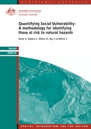
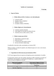
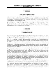
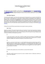
sometimes used to derive test levels. The predictedacoustic environment is adjusted usingstatistical methods to derive a maximum predictedflight environment. Margin is addedto ensure that the hardware is sufficientlyrobust <strong>and</strong> to account <strong>for</strong> analytical uncertaintiesin the derivation of the environment<strong>and</strong> design of the hardware. A typical qualificationmargin is 6 decibels, or four timesthe energy of the maximum predicted environment.The test lasts at least 1 minute toestablish a duration margin of four times theexposure in flight. Additional test time maybe accumulated depending on the programrequirements. Hardware that is susceptible tothe acoustic-pressure loading are items withlarge surfaces <strong>and</strong> low mass density such ascomposite material solar arrays <strong>and</strong> antennareflectors. These composite structures mayhave design or workmanship deficiencies,which result in bond or material failures.Vibration <strong>Testing</strong>As the launch vehicle lifts off from the st<strong>and</strong><strong>and</strong> throughout powered flight, the vibrationcaused by the operating engines excitesthe vehicle <strong>and</strong> spacecraft structure. Additionalvibration is caused by the fluctuatingacoustic pressure experienced during liftoff,transonic flight, <strong>and</strong> the maximum-dynamicpressurephase of flight.Vibration testing helps demonstrate thathardware can withst<strong>and</strong> these conditions.R<strong>and</strong>om vibration tests are conducted onan electrodynamic vibration machine or“shaker,” which consists of a mounting table<strong>for</strong> the test item rigidly attached to a drivecoilarmature. A control system energizesthe shaker to the desired vibration level.Feedback <strong>for</strong> the control system is providedby a series of accelerometers, which aremounted at the base of the test item at locationsthat correspond to where the launchvehicle adapter would be attached. Twocontrol approaches can be used to provide realisticstructural responses. Most spacecraftvibration tests use response-limiting majorappendageaccelerations to reduce input atdiscrete frequencies so as not to cause unrealisticfailures. For test structures that exhibitdistinct, lightly damped resonances on ashaker, <strong>for</strong>ce limiting is used in conjunctionwith input vibration to control the shaker.In the <strong>for</strong>ce-limiting approach, transducersthat measure the input <strong>for</strong>ce are mounted betweenthe test item <strong>and</strong> the shaker. The goalis to reduce the response of the test item at itsresonant frequencies on the shaker to replicatethe response at the combined system atSound pressure levels(decibels)140130120110100908010 100 1000 10,0001/3 Octave frequency (hertz)Maximum predicted acoustic level <strong>for</strong> liftoffMaximum predicted acoustic level <strong>for</strong> transonic/max QMaximum workmanship requirement <strong>for</strong> acoustic testTypical acoustic test level is a smooth envelope plus 6 dB marginthe resonant frequencies that would exist inthe flight-mounting configuration.As in the case of acoustic testing, heritageflight <strong>and</strong> test data are used to predict vibrationtest levels, <strong>and</strong> analytical methods aresometimes used to develop transfer functionsto scale heritage data to new hardware configurations.In most cases, the predicted environmentsare verified later with system-levelacoustic tests <strong>and</strong> rocket engine static firetests. As with acoustic testing, a 6-decibelmargin is typically added to the maximumpredicted environment. Structural failures ofpiece parts, unit assemblies, <strong>and</strong> secondary<strong>and</strong> primary space vehicle structures can <strong>and</strong>do occur from vibration-induced stress <strong>and</strong>material fatigue. Failures of inadequately designedor poorly manufactured or assembledstructural interfaces are commonly revealed.Aerospace personnel, using predictivesoftware, provide analysis confirmation <strong>for</strong>optimal instrumentation <strong>for</strong> vibration testing.Aerospace confirms hardware test perceptiveness<strong>and</strong> effectiveness with analysis,Power spectral density1.000000.100000.010000.001000.00010Typical acoustic test levelused to simulate thelaunch vehicle environment.The spectrum isdivided into 1/3-octaveb<strong>and</strong>s, <strong>and</strong> the soundpressure level is specified<strong>for</strong> each b<strong>and</strong> in decibels.The frequency range istypically from 30 to 10,000hertz.testing experience, <strong>and</strong> consideration ofinterface constraints.Shock <strong>Testing</strong>Stage, fairing, <strong>and</strong> vehicle separations areoften accomplished by means of pyrotechnicdevices such as explosive bolts, separationnuts, bolt cutters, exp<strong>and</strong>ing-tube separationsystems, clamp b<strong>and</strong>s, ordnance thrusters,<strong>and</strong> pressurized bellows. When activated,these devices produce powerful shocks thatcan damage equipment <strong>and</strong> structures. Thecharacteristics of these shocks depend onthe particular separation mechanism, butthe energy spectrum is usually concentratedat or above 500 hertz <strong>and</strong> is measured in afrequency range of 100 to 10,000 hertz. Atypical shock response spectrum plot is usedto gauge the damage potential of a givenseparation event.Separations or deployments generatebrief impulsive loads even if no pyrotechnicdevices are used. Nonexplosive initiatorsmay produce significant shock levels simply0.0000110 100 1000Frequency (hertz)10,000Maximum predicted vibration level <strong>for</strong> liftoffMaximum predicted vibration level <strong>for</strong> transonic/max QMaximum workmanship requirement <strong>for</strong> vibration testTypical vibration test level is a smooth envelope plus 6 dB marginTypical vibration testlevel used to simulatethe launch vehicle environment.A 6-decibelqualification margin istypically added to themaximum predictedenvironment to ensurethat the hardware is sufficientlyrobust.Crosslink Fall 2005 • 13
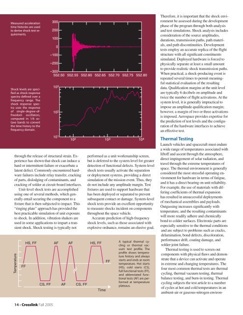
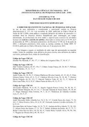
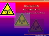
Measured accelerationtime histories are usedto derive shock test requirements.Shock levels are specifiedas shock responsespectra defined over afrequency range. Theshock response spectrauses the responseof single-degree-offreedomoscillators,computed in 1/6 octaveb<strong>and</strong>s to convertthe time history to thefrequency domain.300200100–100–200through the release of structural strain. Experiencehas shown that shock can induce ahard or intermittent failure or exacerbate alatent defect. Commonly encountered hardwarefailures include relay transfer, crackingof parts, dislodging of contaminants, <strong>and</strong>cracking of solder at circuit-board interfaces.Unit-level shock tests are accomplishedusing one of several methods, which generallyentail securing the component to afixture that is then subjected to impact. This“ringing plate” approach has provided thebest practicable simulation of unit exposureto shock. In addition, vibration shakers areused in some applications to impart a transientshock. Shock testing is typically notTemperatureFFHS, FFCS, FF0–300552.50 552.55 552.60 552.65 552.70 552.75 552.8010 310 210 1 10 310 2 10 4AFAFAFCS, FFper<strong>for</strong>med as a unit workmanship screen,but is deferred to the system level <strong>for</strong> greaterdetection of functional defects. System-levelshock tests usually activate the separationor deployment systems, providing a directsimulation of the mission event. Thus, theydo not include any amplitude margin. Testfixtures are used to support hardware thathas been deployed or separated to preventsubsequent contact or damage. System-levelshock tests provide an excellent opportunityto measure shocks incident on componentsthroughout the space vehicle.Accurate prediction of high-frequencyshock levels, such as those associated withexplosive ordnance, remains an elusive goal.HS, FFTimeFFA typical thermal cyclingor thermal vacuumtest profile. Theprofile shows temperaturehistory <strong>and</strong> alwaysstarts <strong>and</strong> ends at roomtemperature. Hot starts(HS), cold starts (CS),full functional tests (FF),<strong>and</strong> abbreviated functionaltests (AF) are per<strong>for</strong>medat temperatureplateaus.There<strong>for</strong>e, it is important that the shock environmentbe assessed during the developmentphase of the program through both analysis<strong>and</strong> test simulations. Shock analysis includesconsideration of the source amplitudes,durations, transmission paths, path materials,<strong>and</strong> path discontinuities. <strong>Development</strong>tests employ an accurate replica of the flightstructure with all significant constituentssimulated. Deployed hardware is <strong>for</strong>ced tophysically separate at least a small amountto provide realistic shock transmission paths.When practical, a shock-producing event isrepeated several times to permit meaningfulstatistical evaluation of the resultingdata. Qualification margins at the unit levelare typically 6 decibels on amplitude <strong>and</strong>twice the number of flight activations. At thesystem level, it is generally impractical toimpose an amplitude qualification margin;however, a margin of two or three activationsis imposed. Aerospace provides expertise <strong>for</strong>the prediction of test levels <strong>and</strong> the configurationof the hardware interfaces to achievean effective test.Thermal <strong>Testing</strong>Launch vehicles <strong>and</strong> spacecraft must endurea wide range of temperatures associated withliftoff <strong>and</strong> ascent through the atmosphere,direct impingement of solar radiation, <strong>and</strong>travel through the extreme temperatures ofspace. The thermal environment is generallyconsidered the most stressful operating environment<strong>for</strong> hardware in terms of fatigue,<strong>and</strong> it has a direct bearing on unit reliability.For example, the use of materials with differingcoefficients of thermal expansionhas resulted in unsuccessful deploymentsof mechanical assemblies <strong>and</strong> payloads.Outgassing increases significantly withtemperature, <strong>and</strong> the resulting contaminantswill more readily adhere <strong>and</strong> chemicallybond to colder surfaces. Electronic parts areespecially sensitive to the thermal conditions<strong>and</strong> are subject to problems such as cracks,delamination, bond defects, discoloration,per<strong>for</strong>mance drift, coating damage, <strong>and</strong>solder-joint failure.Thermal testing is used to screen outcomponents with physical flaws <strong>and</strong> demonstratethat a device can activate <strong>and</strong> operatein extreme <strong>and</strong> changing temperatures. Thefour most common thermal tests are thermalcycling, thermal vacuum testing, thermalbalance testing, <strong>and</strong> burn-in testing. Thermalcycling subjects the test article to a numberof cycles at hot <strong>and</strong> cold temperatures in anambient-air or gaseous-nitrogen environ-14 • Crosslink Fall 2005