AC500, CP400, CP600, DigiVis 500, Wireless Catalog - Gerrie Electric
AC500, CP400, CP600, DigiVis 500, Wireless Catalog - Gerrie Electric
AC500, CP400, CP600, DigiVis 500, Wireless Catalog - Gerrie Electric

You also want an ePaper? Increase the reach of your titles
YUMPU automatically turns print PDFs into web optimized ePapers that Google loves.
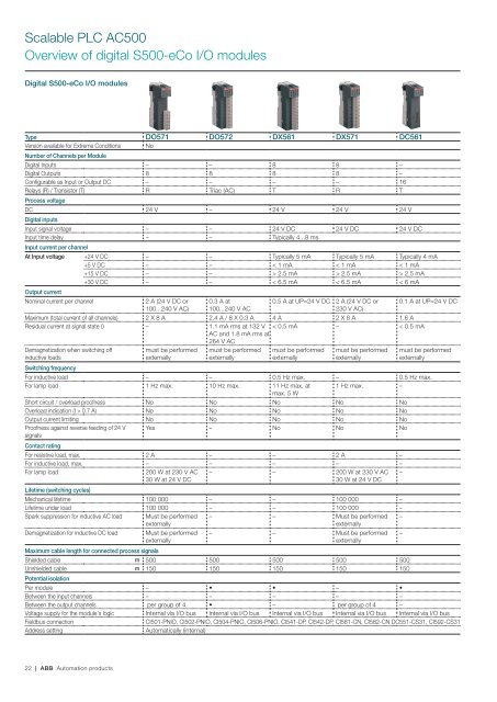
Scalable PLC <strong>AC<strong>500</strong></strong><br />
Overview of digital S<strong>500</strong>-eCo I/O modules<br />
Digital S<strong>500</strong>-eCo I/O modules<br />
Type DO571 DO572 DX561 DX571 DC561<br />
Version available for Extreme Conditions No<br />
Number of Channels per Module<br />
Digital Inputs – – 8 8 –<br />
Digital Outputs 8 8 8 8 –<br />
Configurable as Input or Output DC – – – – 16<br />
Relays (R) / Transistor (T) R Triac (AC) T R T<br />
Process voltage<br />
DC 24 V – 24 V 24 V 24 V<br />
Digital inputs<br />
Input signal voltage – – 24 V DC 24 V DC 24 V DC<br />
Input time delay – – Typically 4...8 ms<br />
Input current per channel<br />
At Input voltage +24 V DC – – Typically 5 mA Typically 5 mA Typically 4 mA<br />
+5 V DC – – < 1 mA < 1 mA < 1 mA<br />
+15 V DC – – > 2.5 mA > 2.5 mA > 2.5 mA<br />
+30 V DC – – < 6.5 mA < 6.5 mA < 6 mA<br />
Output current<br />
Nominal current per channel<br />
2 A (24 V DC or<br />
100...240 V AC)<br />
0.3 A at<br />
100...240 V AC<br />
0.5 A at UP=24 V DC 2 A (24 V DC or<br />
230 V AC)<br />
0.1 A at UP=24 V DC<br />
Maximum (total current of all channels) 2 X 8 A 2.4 A / 8 X 0.3 A 4 A 2 X 8 A 1.6 A<br />
Residual current at signal state 0 – 1.1 mA rms at 132 V < 0.5 mA – < 0.5 mA<br />
AC and 1.8 mA rms at<br />
264 V AC<br />
Demagnetization when switching off<br />
inductive loads<br />
must be performed<br />
externally<br />
must be performed<br />
externally<br />
must be performed<br />
externally<br />
must be performed<br />
externally<br />
must be performed<br />
externally<br />
Switching frequency<br />
For inductive load – – 0.5 Hz max. – 0.5 Hz max.<br />
For lamp load 1 Hz max. 10 Hz max. 11 Hz max. at 1 Hz max. –<br />
max. 5 W<br />
Short circuit / overload proofness No No No No No<br />
Overload indication (I > 0.7 A) No No No No No<br />
Output current limiting No No No No No<br />
Proofness against reverse feeding of 24 V Yes – No No No<br />
signals<br />
Contact rating<br />
For resistive load, max. 2 A – – 2 A –<br />
For inductive load, max. – – – – –<br />
For lamp load<br />
200 W at 230 V AC<br />
30 W at 24 V DC<br />
– – 200 W at 230 V AC<br />
30 W at 24 V DC<br />
Lifetime (switching cycles)<br />
Mechanical lifetime 100 000 – – 100 000 –<br />
Lifetime under load 100 000 – – 100 000 –<br />
Spark suppression for inductive AC load Must be performed<br />
externally<br />
– – Must be performed<br />
externally<br />
–<br />
Demagnetization for inductive DC load Must be performed<br />
externally<br />
Maximum cable length for connected process signals<br />
– – Must be performed<br />
externally<br />
Shielded cable m <strong>500</strong> <strong>500</strong> <strong>500</strong> <strong>500</strong> <strong>500</strong><br />
Unshielded cable m 150 150 150 150 150<br />
Potential isolation<br />
Per module – • • – •<br />
Between the input channels – – – – –<br />
Between the output channels per group of 4 • – per group of 4 –<br />
Voltage supply for the module's logic Internal via I/O bus Internal via I/O bus Internal via I/O bus Internal via I/O bus Internal via I/O bus<br />
Fieldbus connection<br />
CI501-PNIO, CI502-PNIO, CI504-PNIO, CI506-PNIO, CI541-DP, CI542-DP, CI581-CN, CI582-CN DC551-CS31, CI592-CS31<br />
Address setting<br />
Automatically (internal)<br />
–<br />
–<br />
22 | ABB Automation products