AC500, CP400, CP600, DigiVis 500, Wireless Catalog - Gerrie Electric
AC500, CP400, CP600, DigiVis 500, Wireless Catalog - Gerrie Electric
AC500, CP400, CP600, DigiVis 500, Wireless Catalog - Gerrie Electric

Create successful ePaper yourself
Turn your PDF publications into a flip-book with our unique Google optimized e-Paper software.
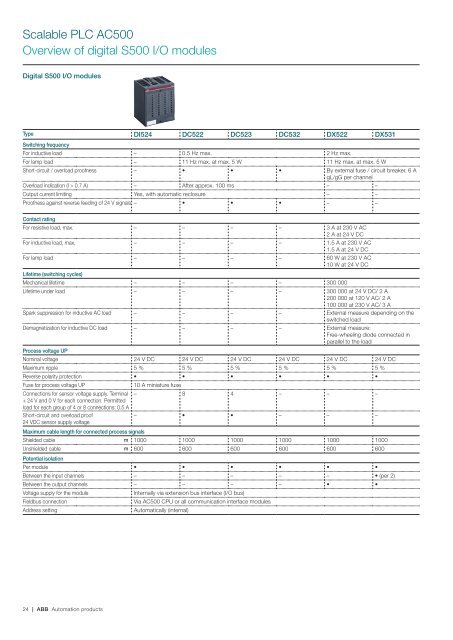
Scalable PLC <strong>AC<strong>500</strong></strong><br />
Overview of digital S<strong>500</strong> I/O modules<br />
Digital S<strong>500</strong> I/O modules<br />
Type DI524 DC522 DC523 DC532 DX522 DX531<br />
Switching frequency<br />
For inductive load – 0.5 Hz max. 2 Hz max.<br />
For lamp load – 11 Hz max. at max. 5 W 11 Hz max. at max. 5 W<br />
Short-circuit / overload proofness – • • • By external fuse / circuit breaker. 6 A<br />
gL/gG per channel<br />
Overload indication (I > 0.7 A) – After approx. 100 ms – –<br />
Output current limiting Yes, with automatic reclosure – –<br />
Proofness against reverse feeding of 24 V signals – • • • – –<br />
Contact rating<br />
For resistive load, max. – – – – 3 A at 230 V AC<br />
2 A at 24 V DC<br />
For inductive load, max. – – – – 1.5 A at 230 V AC<br />
1.5 A at 24 V DC<br />
For lamp load – – – – 60 W at 230 V AC<br />
10 W at 24 V DC<br />
Lifetime (switching cycles)<br />
Mechanical lifetime – – – – 300 000<br />
Lifetime under load – – – – 300 000 at 24 V DC/ 2 A<br />
200 000 at 120 V AC/ 2 A<br />
100 000 at 230 V AC/ 3 A<br />
Spark suppression for inductive AC load – – – – External measure depending on the<br />
switched load<br />
Demagnetization for inductive DC load – – – – External measure:<br />
Free-wheeling diode connected in<br />
parallel to the load<br />
Process voltage UP<br />
Nominal voltage 24 V DC 24 V DC 24 V DC 24 V DC 24 V DC 24 V DC<br />
Maximum ripple 5 % 5 % 5 % 5 % 5 % 5 %<br />
Reverse polarity protection • • • • • •<br />
Fuse for process voltage UP<br />
10 A miniature fuse<br />
Connections for sensor voltage supply. Terminal – 8 4 – – –<br />
+ 24 V and 0 V for each connection. Permitted<br />
load for each group of 4 or 8 connections: 0.5 A<br />
Short-circuit and overload proof<br />
– • • – – –<br />
24 VDC sensor supply voltage<br />
Maximum cable length for connected process signals<br />
Shielded cable m 1000 1000 1000 1000 1000 1000<br />
Unshielded cable m 600 600 600 600 600 600<br />
Potential isolation<br />
Per module • • • • • •<br />
Between the input channels – – – – – • (per 2)<br />
Between the output channels – – – – • •<br />
Voltage supply for the module<br />
Internally via extension bus interface (I/O bus)<br />
Fieldbus connection<br />
Via <strong>AC<strong>500</strong></strong> CPU or all communication interface modules<br />
Address setting<br />
Automatically (internal)<br />
24 | ABB Automation products