Aquamicron® Filter Elements - Hydac
Aquamicron® Filter Elements - Hydac
Aquamicron® Filter Elements - Hydac

Create successful ePaper yourself
Turn your PDF publications into a flip-book with our unique Google optimized e-Paper software.
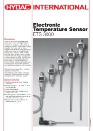
1. DESCRIPTION<br />
The presence of water in<br />
hydraulic media causes many<br />
problems, for example, the<br />
saturation of very fine filters or<br />
jamming of valves, and these<br />
problems are often wrongly<br />
attributed to excessive levels of<br />
solid particle contamination.<br />
In addition to this the build-up of<br />
rust and the reduction in<br />
lubrication on bearings and slides<br />
can lead to considerable<br />
impairment in the functioning of a<br />
system. In other words, water is<br />
a serious "contaminant" of a<br />
hydraulic medium.<br />
Since methods usually employed<br />
up to now to extract water have,<br />
on the whole, proved to be<br />
uneconomical compared to the<br />
purchase price of a system,<br />
HYDAC Aquamicron ® technology<br />
offers an economically sound, yet<br />
effective, method of separating<br />
water from hydraulic media.<br />
Aquamicron® filter elements are<br />
specially designed to separate<br />
water from mineral oils, HFD-R<br />
oils and biodegradable oils.<br />
They are only available in the<br />
dimensions of the HYDAC HC<br />
return line filter elements from<br />
size 330 upwards. This means<br />
that they can be installed in all<br />
HYDAC filter housings from size<br />
330/331 upwards, which are fitted<br />
with return line filter elements.<br />
The increasing pressure loss in a<br />
filter element which is being<br />
saturated with water indicates,<br />
by means of standard clogging<br />
indicators, that it is time to change<br />
the element. When Aquamicron ®<br />
technology is employed, solid<br />
particle contaminants are also<br />
separated from the hydraulic<br />
medium as a side-effect.<br />
This means that the Aquamicron ®<br />
element doubles as a safety filter.<br />
The "filtration rating" is<br />
40 µm absolute (β 40<br />
≥100 to<br />
∆p = 3 bar). In order to guarantee<br />
greatest efficiency it is<br />
recommended that they are<br />
installed off-line.<br />
Note:<br />
The Aquamicron ® elements are<br />
disposable items.<br />
1.1. PRINCIPLES OF AQUAMICRON ® TECHNOLOGY<br />
The separation of water from hydraulic fluids with the aid of the super<br />
absorber embedded in the filter material is based on a physical-chemical<br />
reaction. The super absorber reacts with the water present in the medium<br />
and expands to form a gel, from which the water present in the medium can<br />
no longer be extracted even by increasing the pressure.<br />
The Aquamicron ® technology is capable of absorbing circulating water, be it<br />
emulsified or free. These filter elements cannot remove dissolved water from<br />
the system, i.e. water below the saturation level of the hydraulic medium.<br />
The following principles apply to Aquamicron ® technology:<br />
High water content ⇒ High absorption rate<br />
Low water content ⇒ Low absorption rate<br />
Unsaturated filter element ⇒ High absorption rate<br />
Saturated filter element ⇒ Low absorption rate<br />
Hydraulic Absorption rate <br />
filter area load Water retention capacity <br />
(l/min cm²) Residual water content <br />
Static pressure Absorption rate =<br />
Water retention capacity =<br />
Residual water content<br />
<br />
Pressure and flow-rate Absorption rate <br />
fluctuations present Water retention capacity <br />
Residual water content<br />
<br />
Dispersion/detergent Absorption rate <br />
additive present Water retention capacity =<br />
Residual water content<br />
<br />
Key to symbols: increases decreases = constant<br />
2. GENERAL<br />
Max. permissible operating<br />
pressure<br />
25 bar<br />
Max. permissible ∆p<br />
across element<br />
10 bar<br />
Temperature range<br />
0 °C to +100 °C<br />
Compatibility with hydraulic<br />
media<br />
Mineral oils:<br />
test criteria to ISO 2943<br />
Lubricating oils:<br />
test criteria to ISO 2943<br />
Other media on request<br />
Cracking pressure of the<br />
bypass valve<br />
∆p o<br />
= 3 bar +10%<br />
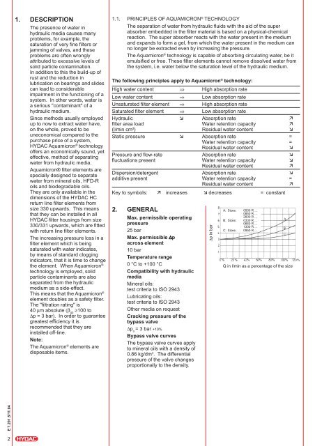
Bypass valve curves<br />
The bypass valve curves apply<br />
to mineral oils with a density of<br />
0.86 kg/dm 3 . The differential<br />
pressure of the valve changes<br />
proportionally to the density.<br />
∆p in bar<br />
A: Sizes: 0500 R ...<br />
0850 R ...<br />
2600 R ...<br />
B: Sizes: 0330 R ...<br />
0660 R ...<br />
1300 R ...<br />
C: Sizes: 0950 R ...<br />
Q in l/min as a percentage of the size<br />
E 7.201.5/11.04<br />
2