Pump-Transfer Cooler Filtration Unit
Pump-Transfer Cooler Filtration Unit
Pump-Transfer Cooler Filtration Unit

Create successful ePaper yourself
Turn your PDF publications into a flip-book with our unique Google optimized e-Paper software.
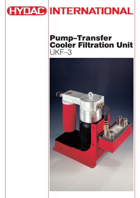
<strong>Pump</strong>–<strong>Transfer</strong><br />
<strong>Cooler</strong> <strong>Filtration</strong> <strong>Unit</strong><br />
UKF–3
PUMP-TRANSFER COOLER FILTRATION UNIT<br />
UKF<br />
1. GENERAL<br />
1.1. DESCRIPTION<br />
The UKF pump-transfer cooler filtration unit is a<br />
compact, easy-to-install unit for off-line filtration cooling<br />
circuits. Installation is simply a matter of hydraulic inline<br />
mounting to and from the tank and connecting the<br />
voltage supply.<br />
1.2. FEATURES<br />
Off-line unit consisting of:<br />
• low-noise feed pump<br />
• filter<br />
• oil-water plate heat exchanger<br />
• the circuit is fitted with check valves to isolate the filter<br />
when used with a positive head tank when changing the<br />
filter element<br />
1.3. APPLICATIONS<br />
• plastic injection moulding machines<br />
• presses<br />
• machining centres<br />
• wind generators<br />
• transmission systems<br />
1.4. SYMBOLS<br />
(shown with electrical differential pressure indicator)<br />
UF (without heat exchanger)<br />
optional<br />
UKF<br />
optional<br />
2
2. TECHNICAL SPECIFICATIONS<br />
2.1. OPERATING PRESSURE<br />
Oil side: max. 10 bar<br />
Water side: max. 27 bar (static)<br />
2.2. SUCTION PRESSURE ACROSS THE SUCTION<br />
CONNECTION<br />
-0.4 bar<br />
2.3. MEDIUM<br />
Oil side:<br />
Mineral oil to DIN 51524 part 1 and 2.<br />
Permissible contamination ≤ NAS 12<br />
2.4. TEMPERATURE OF MEDIUM<br />
Oil side: +10 °C to +80 °C<br />
Water side: + 5 °C to +60 °C<br />
2.5. MAX. VISCOSITY<br />
See graph on page 6<br />
2.6. AMBIENT TEMPERATURE<br />
+ 10 °C to + 40 °C<br />
2.7. MOUNTING POSITION<br />
Vertical<br />
2.8. PRESSURE DIFFERENTIALS AT ν = 46 mm²/s<br />
• Housing<br />
0.5 bar<br />
• Check valves: 1 bar<br />
• Filter: see page 8<br />
• Heat exchanger: see page 9<br />
2.9. REVOLUTIONS<br />
min. 900 rpm to<br />
max. 1800 rpm<br />
2.10. DIRECTION OF ROTATION<br />
Clockwise – see direction of arrow<br />
2.11. WEIGHT (dry unit)<br />
(UF + heat exchanger + filter)<br />
UF:<br />
1.5 KW 44 kg<br />
2.2 KW 48 kg<br />
4 KW 52 kg<br />
Heat exchanger:<br />
410 - 20 11 kg<br />
410 - 40 14 kg<br />
410 - 70 17 kg<br />
410 - 100 22 kg<br />
410 - 120 25 kg<br />
415 - 20 14 kg<br />
415 - 40 18 kg<br />
415 - 60 24 kg<br />
415 - 80 30 kg<br />
Filter:<br />
MF 180 2 kg<br />
LF 330 4 kg<br />
LF 500 6 kg<br />
2.12. DRIVE<br />
Three-phase electric motor<br />
Insulation class: F<br />
Safety type: IP55<br />
2.13. VOLUMETRIC EFFICIENCY<br />
> 90 % (n = 40 mm²/s)<br />
2.14. NOISE LEVELS<br />
(at 1500 rpm)<br />
<strong>Pump</strong> [cm 3 /rev] 1 bar 6 bar<br />
20 61 61<br />
30 61 62<br />
40 62 63<br />
50 64 66<br />
70 67 68<br />
100 68 70<br />
130 70 72<br />
Test medium: ISO-VG 46 at 40 °C<br />
The noise levels are only a guide as acoustic properties<br />
of a room, connections, viscosity and reflections have<br />
an effect on the noise level.<br />
2.15. OPERATING DATA FOR HEAT EXCHANGER<br />
• Medium (water side):<br />
– Water glycol (coolant)<br />
– HFC operating fluids<br />
– Water<br />
–Oil<br />
• Contamination:<br />
The amount of particles in suspension should be less<br />
than 10 mg/l. Particle size < 0.6 mm (spherical).<br />
Thread-like particles cause a rapid increase in pressure<br />
drops.<br />
• Corrosion:<br />
The following critical values refer to a pH value of 7<br />
– Free chlorine:<br />
CL 2<br />
< 0.5 ppm<br />
– Chloride ions:<br />
CL < 700 ppm at 20 °C<br />
< 200 ppm at 50 °C<br />
– Other critical values:<br />
- pH 7 - 10<br />
2-<br />
- Sulphate SO 4<br />
< 100 ppm<br />
2-<br />
- [H CO 3<br />
-] / [SO 4<br />
] > 1<br />
- Ammonia, NH 3<br />
< 10 ppm<br />
- Free CO < 10 ppm<br />
The following ions are not corrosive under normal<br />
conditions:<br />
Phosphate, nitrate, nitrite, iron, manganese, sodium<br />
and potassium.<br />
• Heat exchanger connections<br />
Female thread (max. torque rating: 385 Nm).<br />
The pipes must be connected so that the connections<br />
are stress-free. Linear expansion and vibrations from<br />
the pipes to the heat exchanger must be avoided.<br />
3
3. MODEL CODE<br />
(also order code)<br />
UKF -3 / 1.0 / P / 70 / 2.2 / 410–70 / MF180/10 / D<br />
UF -3 / 1.0 / P / 70 / 2.2 / – / MF180/10 / D<br />
Type<br />
UKF<br />
UF<br />
pump + heat exchanger + filter<br />
pump + filter<br />
Model<br />
1.0 UF<br />
UKF heat exchanger at the back (410)<br />
2.0 heat exchanger at the side (415)<br />
(see also Dimensions on page 7)<br />
Seals<br />
P<br />
Perbunan<br />
<strong>Pump</strong> flow rate: cm 3 /rev<br />
cm 3 /rev 1000 rpm 1500 rpm<br />
20 20 l/min 30 l/min<br />
30 30 l/min 45 l/min<br />
40 40 l/min 60 l/min<br />
50 – 75 l/min<br />
70 – 105 l/min<br />
100 – 150 l/min<br />
130 – 185 l/min<br />
Motor<br />
1.5 KW - 1000 rpm - 4 A<br />
2.2 KW - 1500 rpm - 5.2 A<br />
4 KW - 1500 rpm - 9 A<br />
Wide voltage range motor:<br />
All voltages and frequencies between<br />
380/420V - 50Hz and<br />
440/480V - 60Hz possible<br />
For calculation, see page 5<br />
Heat exchanger UKF<br />
Model 1.0 2.0<br />
410 - 20 415 - 20<br />
40 40<br />
70 60<br />
100 80<br />
120<br />
UF without heat exchanger: –<br />
For calculation, see page 5<br />
Filter<br />
MF180<br />
LF330<br />
LF500<br />
<strong>Filtration</strong> rating<br />
Contamination retention at ∆p: 5 bar<br />
MF180 LF330 LF500<br />
3 3 µm absolute 89 g 36.9 60.7<br />
5 5 µm absolute 90 g 39.4 64.8<br />
10 10 µm absolute 94 g 44.3 72.9<br />
20 20 µm absolute 111 g 49.2 81<br />
10P 10 µm nominal 120 g – –<br />
For further details on filter elements, see Mobile Spin-On Filters<br />
brochure no.: E 7.301../.., and Filter Elements brochure no.:<br />
E 7.200../.., for Betamicron ® 3 plus pressure filter elements<br />
To determine the pressure differential, see page 8<br />
Differential pressure clogging indicator 5 bar<br />
BM VD 5 BM.1 (visual; manual reset)<br />
C VD 5 C.0 (electrical)<br />
D VD 5 D.0/-L24 (electrical/visual)<br />
For further details, see Clogging Indicator brochure no.:<br />
E 7.050../..<br />
4
4. DETERMINING THE COOLING<br />
CAPACITY OF UKF<br />
PRE-SELECTION GRAPHS<br />
(see also point 12 and 13)<br />
UKF-3/1.0<br />
Parameters:<br />
T oil<br />
= 55 °C Qoil<br />
= 4 (see graph at point 6)<br />
Oil ISO VG 46 Q H 2<br />
0<br />
UKF-3/2.0<br />
p cooler<br />
[kW]<br />
p cooler<br />
[kW]<br />
T water<br />
[°C]<br />
T water<br />
[°C]<br />
TABLES FOR ACCURATE DETERMINATION OF COOLING CAPACITY<br />
*P: cooling capacity example at T oil<br />
= 55 °C and T H2 O = 20 °C The cooling capacity is also dependent on the viscosity. At a<br />
410-20 410-40 410-70 410-100 410-120<br />
L/min Foil FH 2 O K P* Foil FH 2 O K P* Foil FH 2 O K P* Foil FH 2 O K P* Foil FH 2 O K P*<br />
20 0.200 0.137 -2.50 5.8 0.200 0.154 -1.80 6.1 0.200 0.198 0.20 7.2 0.220 0.225 0.50 8.1 0.240 0.350 0.10 8.6<br />
30 0.300 0.205 -3.90 8.5 0.320 0.212 -4.40 9.0 0.280 0.250 -0.90 9.5 0.300 0.292 0.10 10.8 0.320 0.310 0.00 11.4<br />
40 0.360 0.273 -3.50 10.8 0.420 0.280 -5.70 11.8 0.400 0.300 -4.00 12.0 0.360 0.345 0.00 12.9 0.380 0.374 0.30 13.7<br />
45 0.360 0.298 -2.20 11.6 0.480 0.309 -7.00 13.2 0.480 0.320 -6.50 13.5 0.400 0.367 -0.70 14.0 0.400 0.400 0.80 14.8<br />
60 0.400 0.360 -1.00 13.8 0.620 0.420 -8.40 17.3 0.660 0.415 -10.10 17.9 0.620 0.436 -7.30 18.1 0.560 0.470 -3.00 18.4<br />
75 0.460 0.410 -1.30 15.8 0.740 0.515 -9.30 21.1 0.800 0.520 -11.60 22.0 0.820 0.525 -12.20 22.4 0.780 0.540 -9.60 22.5<br />
105 0.660 0.500 -6.20 20.1 0.780 0.680 -3.10 26.2 1.120 0.725 -16.70 30.4 1.100 0.737 -15.00 30.8 1.140 0.737 -16.70 31.3<br />
150 0.880 0.645 -9.40 26.1 0.960 0.840 -3.40 32.6 1.340 1.030 -12.30 40.8 1.560 1.040 -21.60 43.4 1.580 1.040 -22.30 43.8<br />
185 1.020 0.750 -10.80 30.3 1.140 0.943 -6.60 37.2 1.340 1.210 -3.30 46.2 1.880 1.275 -25.20 52.7 1.980 1.290 -29.30 53.8<br />
415-20 415-40 415-60 415-80<br />
L/min Foil FH 2 O K P* Foil FH 2 O K P* Foil FH 2 O K P* Foil FH 2 O K P*<br />
20 0.280 0.205 -3.00 8.3 0.250 0.235 -0.45 8.6 0.260 0.265 0.40 9.4 0.280 0.283 0.30 10.0<br />
30 0.400 0.310 -3.70 12.1 0.430 0.320 -4.55 12.7 0.380 0.355 -0.80 13.0 0.400 0.386 -0.40 13.9<br />
40 0.520 0.400 -4.70 15.9 0.580 0.418 -6.80 16.7 0.560 0.437 -5.10 17.0 0.500 0.475 -0.70 17.3<br />
45 0.560 0.450 -4.70 17.4 0.640 0.465 -7.10 18.8 0.640 0.480 -6.60 19.0 0.600 0.514 -3.40 19.3<br />
60 0.620 0.575 -1.30 21.3 0.860 0.618 -10.10 24.8 0.880 0.630 -10.60 25.2 0.840 0.640 -8.10 25.3<br />
75 0.720 0.670 -1.40 24.8 1.040 0.770 -11.30 30.5 1.060 0.780 -11.70 31.0 1.120 0.780 -14.20 31.8<br />
105 0.900 0.830 -1.70 31.2 1.220 1.050 -6.30 39.8 1.440 1.080 -14.80 42.8 1.560 1.090 -20.00 44.0<br />
150 1.480 1.370 -3.00 51.0 1.820 1.530 -11.60 57.9 2.100 1.550 -23.00 61.5<br />
185 1.680 1.570 -2.30 58.7 1.920 1.810 -2.40 67.0 2.300 1.900 -16.00 72.5<br />
For T oil<br />
from 45 to 55 °C Qoil<br />
from 10 to 35 °C QH<br />
T H2 O<br />
2 O<br />
Oil ISO VG 46<br />
P cool<br />
= F oil<br />
× T oil in<br />
– F H2 O × T H2 O in + K<br />
= 4 (see graph at point 6)<br />
A calculation program is available for making an accurate<br />
calculation.<br />
The following details are required:<br />
• Oil type<br />
• Required tank temperature with UKF<br />
• Required cooling capacity<br />
• Water inlet temperature and max. water quantity.<br />
Areas shaded grey:<br />
Figures in bold:<br />
not recommended<br />
(∆p too high or efficiency of<br />
heat exchanger too low)<br />
preferred values<br />
lower viscosity the cooling capacity increases, at a higher<br />
viscosity it decreases.<br />
5
5. GRAPHS FOR MOTOR-PUMP SELECTION<br />
.<br />
.<br />
VISCOSITY / TEMPERATURE GRAPH<br />
To DIN 51519 Viscosity index 50<br />
VISCOSITY / TEMPERATURE GRAPH<br />
Viscosity index 0 to 200, oil ISO VG 320<br />
100000<br />
kinematic viscosity in mm 2 /s<br />
kinematic viscosity in mm 2 /s<br />
10000<br />
1000<br />
100<br />
10<br />
VI = 200<br />
VI = 150<br />
VI = 100<br />
VI = 50<br />
VI = 0<br />
temperature in °C<br />
1<br />
0 10 20 30 40 50 60 70 80 90 100<br />
temperature in °C<br />
The viscosity index (VI) indicates how much the viscosity of the oil changes with temperature.<br />
The higher the viscosity index, the smaller the change in viscosity in relation to the temperature.<br />
⇒ Oils with a high viscosity index have a lower viscosity at low temperatures than oils with a low viscosity index.<br />
6
6. OUTPUT CORRECTION<br />
with higher water through-put<br />
Calculation of the oil and water outlet temperature<br />
Temperature loss: oil<br />
P P = cooling capacity [kW]<br />
∆T ≈ 36 ×<br />
Q Oil<br />
Q Oil<br />
= flow rate [l/min]<br />
Temperature increase: water<br />
∆T ≈ 14.4 ×<br />
P P = cooling capacity [kW]<br />
Q water<br />
Q water<br />
= flow rate [l/min]<br />
Oil<br />
factor Lp<br />
Oil<br />
Oil<br />
Oil<br />
∆T (Oil in - H2 O in) [K ]<br />
7
7. DIMENSIONS<br />
UF-3/1.0<br />
ca.<br />
SAE 2"<br />
3000 PSI<br />
Oil in<br />
approx.<br />
Size<br />
approx.<br />
approx.<br />
SAE 2"<br />
3000 PSI<br />
Oil in<br />
approx.<br />
approx.<br />
Indicator<br />
Oil out<br />
G1<br />
approx.<br />
UKF-3/1.0 SAE 2"<br />
3000 PSI<br />
Oil in<br />
approx.<br />
Size<br />
approx.<br />
SAE 2"<br />
3000 PSI<br />
Oil in approx.<br />
approx.<br />
G1<br />
internal<br />
Oil<br />
Indicator<br />
Water<br />
approx.<br />
approx.<br />
approx.<br />
G1<br />
internal<br />
8
UKF-3/2.0<br />
SAE 2"<br />
3000 PSI<br />
Oil in<br />
Size<br />
approx.<br />
approx.<br />
approx.<br />
SAE 2"<br />
3000 PSI approx.<br />
Oil in<br />
approx.<br />
Indicator<br />
G1<br />
internal<br />
Oil G1<br />
internal<br />
Water<br />
approx.<br />
9
8. FILTER SIZE – FILTER MATERIAL – FILTRATION RATING<br />
8.1. SELECTING THE FILTRATION RATING ACCORDING TO MANUFACTURERS’ AND OPERATORS’ EXPERIENCE<br />
Permissible contam- Suggested filtration rating Type of hydraulic system<br />
ination class to<br />
NAS 1638 ISO 4406<br />
x in µm (β x<br />
= 100)<br />
3 14/12/9 3 µm To prevent fine contamination in highly sensitive systems<br />
4 15/13/10 with a high reliability requirement, primarily aerospace and<br />
5 16/14/11 laboratory conditions.<br />
5 16/14/11 3 - 5 µm Sensitive high performance systems & control systems in<br />
6 17/15/12 high pressure applications, frequently in aerospace<br />
technology, industrial robots and machine tools where<br />
proportional and servo valves are used.<br />
7 18/16/13 5 - 10 µm High performance industrial hydraulic systems with high<br />
8 19/17/14 level of operating safety, using precision hydraulic<br />
components such as, for example, control pumps.<br />
8 19/17/14 10 - 20 µm General hydraulic and mobile hydraulic systems with<br />
9 20/18/15 conventional directional valve controls<br />
10 21/19/16<br />
9 20/18/15 15 - 25 µm Systems in heavy machinery hydraulics, primarily in the<br />
10 21/19/16 low pressure sector<br />
11 22/20/17<br />
11 22/20/17 20 - 40 µm Low pressure systems with large tolerances and low<br />
12 23/21/18 demands for contamination protection<br />
8.2. PRESSURE DIFFERENTIAL – FILTER ELEMENT<br />
Filter curves<br />
Gradient coefficient [K∆ element<br />
] at 30 mm²/s<br />
<strong>Filtration</strong> rating<br />
3µm 5µm 10µm 20µm 10P<br />
MF180 0.0025 0.0020 0.0018 0.0009 0.0016<br />
LF330 0.00606 0.00485 0.00333 0.00194 –<br />
LF500 0.00420 0.00300 0.00180 0.00140 –<br />
∆p element<br />
= [K∆ element<br />
] × Q [l/min] ×<br />
operating viscosity [mm²/s]<br />
30 mm²/s<br />
9. NOTES ON INLINE MOUNTING<br />
The pressure differential in a hydraulic line is<br />
dependent on:<br />
1) Flow rate<br />
2) Kinematic viscosity<br />
3) Pipe dimensions<br />
and can be estimated for hydraulic oils as follows:<br />
∆ l<br />
p ≈ 5.84 × Q bar<br />
4<br />
d<br />
× ×υ⎡ ⎣ ⎤ ⎦<br />
l = pipe length [m]<br />
d = pipe internal diameter [mm]<br />
Q = flow rate [l/min]<br />
ν = kinematic viscosity [mm²/s]<br />
This applies to straight pipe runs and hydraulic oils<br />
• Additional threaded connections and pipe bends<br />
increase the pressure differential<br />
Note: – As few threaded connections as possible<br />
– Few pipe bends; if required, use large radius<br />
– Difference in height between pump and oil<br />
level as small as possible<br />
– Hoses must be suitable for a vacuum of<br />
min. 5000 mmW (e.g. hoses to be<br />
steel-reinforced (wire-braided))<br />
– Do not reduce pipe cross-section<br />
predetermined by the unit<br />
10
10. TABLE OF PRESSURE DROPS VIA HEAT EXCHANGER<br />
(for T oil<br />
= 45 °C ISO VG 46)<br />
410-20 410-40 410-70 410-100 410-120 415-20 415-40 415-60 415-80<br />
L/min ∆p[bar] ∆p[bar] ∆p[bar] ∆p[bar] ∆p[bar] ∆p[bar] ∆p[bar] ∆p[bar] ∆p[bar]<br />
20 0.36 0.18 0.11 0.08 0.06 0.65 0.30 0.20 0.15<br />
30 0.59 0.27 0.16 0.11 0.10 1.07 0.45 0.30 0.23<br />
40 0.83 0.35 0.21 0.15 0.13 1.52 0.62 0.39 0.30<br />
45 0.95 0.40 0.23 0.17 0.14 1.76 0.72 0.45 0.33<br />
60 1.37 0.56 0.31 0.22 0.19 2.50 1.02 0.62 0.45<br />
75 1.96 0.74 0.39 0.28 0.24 3.47 1.34 0.81 0.58<br />
105 3.47 1.11 0.58 0.40 0.34 6.12 2.02 1.23 0.87<br />
150 6.35 1.87 0.92 0.63 0.53 3.28 1.92 1.37<br />
185 9.26 2.68 1.20 0.83 0.70 4.62 2.51 1.80<br />
11. CALCULATION OF PRESSURE<br />
DIFFERENTIAL AT OPERATING<br />
PRESSURE<br />
• Pressure drops at operating temperature<br />
11.1. FILTER ELEMENT:<br />
Calculation of the clean element according<br />
to point 8.2. to approx. 1 bar<br />
11.2. HEAT EXCHANGER AND PIPE ON PRESSURE SIDE<br />
Max. 2 bar combined (see point 9. and 10.)<br />
11.3. PIPE ON THE SUCTION SIDE<br />
Max. 0.4 bar (see point 9.)<br />
12. NOTES ON CALCULATING THE UKF<br />
12.1. ESTIMATE OF THE COOLING CAPACITY<br />
REQUIREMENT FOR MINERAL OIL<br />
12.1.1 Via increase in tank temperature:<br />
13. SIZING A UKF USING THE 25% RULE<br />
Cooling capacity ≈ 25% of the installed electrical power<br />
Circulating volume ≈ 25% of the tank volume<br />
Water quantity ≈ 25% of the oil quantity<br />
Note:<br />
All calculations for the heat exchanger are based on oil<br />
data provided by the company Aral.<br />
14. NOTE<br />
The information in this brochure relates to the operating<br />
conditions and applications described.<br />
For applications or operating conditions not described,<br />
please contact the relevant technical department.<br />
Subject to technical modifications.<br />
∆T×<br />
V 1<br />
P = ×<br />
t 35<br />
P<br />
= heat dissipation [kW]<br />
∆T = temperature increase in tank [°C]<br />
V = tank contents [l]<br />
t = operating time [min]<br />
Example:<br />
In a system the tank temperature increases<br />
from 20 °C to 70 °C (= 50 K) in 30 minutes<br />
The tank volume is 400 l<br />
50 × 400 1<br />
P = ×<br />
30 35<br />
P = 19 [kW]<br />
12.1.2 Via the installed electric power<br />
Cooling capacity ≈ 25% of the installed electrical power<br />
11