Return Line Filter RF
Return Line Filter RF
Return Line Filter RF
- No tags were found...

You also want an ePaper? Increase the reach of your titles
YUMPU automatically turns print PDFs into web optimized ePapers that Google loves.
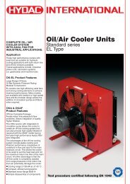
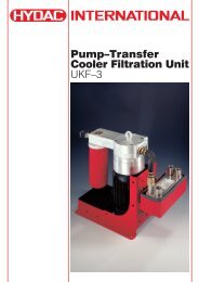
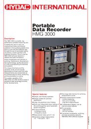
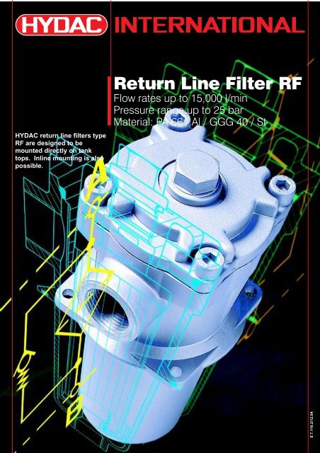
HYDAC return line filters type<strong>RF</strong> are designed to bemounted directly on tanktops. Inline mounting is alsopossible.<strong>Return</strong> <strong>Line</strong> <strong>Filter</strong> <strong>RF</strong>Flow rates up to 15,000 l/minPressure range up to 25 barMaterial: PA 66 / Al / GGG 40 / StE 7.116.2/12.04
E 7.116.2/12.0421. TECHNICALSPECIFICATIONS1.1. FILTER HOUSINGConstructionThe return line filter consists of aone-piece housing with bolt-oncover plate.A connection for a cloggingindicator is standard.The filter is designed to be usedin hydraulic tanks to DIN 24339,cover plate Form C.1.2. FILTER ELEMENTSOriginal Hydac filter elementsguarantee reliable function andprotect hydraulic components andsystems which are sensitive tocontamination from wear and tear.Performance and quality testsaccording to internationalstandards guarantee reliableoperation of the filter.HYDAC filters are validated andtheir quality is continuouslymonitored according to thefollowing standards:– DIN ISO 2941:Verification of collapse / burstresistance– DIN ISO 2942:Verification of fabrication integrity anddetermination of first bubble point– DIN ISO 2943:Verification of materialcompatibility with fluids– ISO 3724:Verification of flow fatiguecharacteristics– ISO 3968:Evaluation of pressure dropversus flow characteristics– ISO 4572/ISO16889:Multi-pass method for evaluatingfiltration performanceIn addition to guaranteeingretention and flow ratecharacteristics, the filter elementshave excellent structural stability.The careful construction andmechanically stable support of thefilter media guarantee aboveaveragebeta value stability andflow fatigue characteristics of thefilter elements.The filter elements are availablewith the following collapse/burststability values:Betamicron ® (BN3HC) : 25 barPaper (P/HC) : 10 barWire mesh (W/HC) : 30 barStainless steel fibre (V) : 210 barBetamicron ® /Aquamicron ® (BN/AM) : 10 barAquamicron ® (AM) : 10 barNote:When changing from the old BN, P,W and V elements to BN3HC,P/HC, W/HC and V/HC elements,the contamination retainer mustalso be changed.1.3. CLOGGING INDICATORSType of indicatorVR = return line indicatorPressure setting2 = 2 bar standardIndicator type codeB. = visualC. = electricalD. = visual/electricalModification numberX = the latest version is always suppliedSupplementary details–V = FPM seals, filter suitable for rapidly biodegradable oils and phosphateester (HFD-R)–LED= 2 light-emitting diodes up to 24 volt–L... = light with corresponding voltage (24, 48, 110, 220 volt)For further details on clogging indicators, please see:Brochure no.: E 7.050../..1.4. SEALSChoice of Perbunan (NBR) orViton (FPM) for HFD fluids1.5. SPECIAL MODELS ANDACCESSORIES– <strong>Filter</strong> housing for sizes 60, 160and 330 in GGG 40 (SG iron)– <strong>Filter</strong> housing surface electro-lessnickel-plated (only possible onGGG 40)– On sizes 2500 and over, suppliedwith cover plate lifting device– Mating flanges available for filtersfrom size 330 and above1.6. SPARE PARTSSee Original Spare Parts List andMaintenance Instructions,brochure no. E 7.103.E./..1.7. COMPATIBILITY WITHOPERATING FLUIDSDIN ISO 2943:– Hydraulic oils H to HLPD toDIN 51524– Lubrication oils to DIN 51517,APJ, ACEA, DIN 51515,ISO 6743– Compressor oils to DIN 51506– Rapidly biodegradable operatingfluids to VDMA 24568HETG, HEES, HEPG– Non-flam operating fluids HFCand HFD– Operating fluids with high watercontent (>50 % water content) onrequestFor further details on filterelements:Brochure no.: E 7.200../..2. GENERALMountingTank-top filter or inline filterDirection of flowInlet: sideOutlet: vertically downTemperature range-10 °C ... +100 °COther temperature ranges onrequestPressure setting of the returnline indicator∆p a= 2 bar -0.2 bar(compared to atmospheric pressure)Other pressure settings on requestCracking pressure of bypassvalve∆p O= 3 bar +0.5 barOther cracking pressures onrequestHydraulic symbolVR 2 D . X /-L220
3. MODEL CODE (also order example)3.1. COMPLETE FILTER<strong>RF</strong> BN/HC 330 D L 10 D 1 .X /-L24<strong>Filter</strong> type<strong>Filter</strong> material of elementBN/HC Betamicron ® (BN3HC)AM Aquamicron ®BN/AM Betamicron ® /Aquamicron ®P/HC paperW/HC stainless steel wire meshV stainless steel fibreSize / Housing materialPA 66: 30Al: 60, 110, 160, 240, 330SG iron (GGG40): 660, 950, 1300Welded steel: 2500, 4000, 5200, 6500, 7800, 15000Operating pressureB = 10 bar (Size 30, 2500 - 15000)D = 25 bar (Size 60 - 1300)Type of connection / Connection sizeCode Type of <strong>Filter</strong> sizeconnection 30 60 110 160 240 330 660 950 1300 2500 4000 5200 6500 7800 15000B G ½ •C G ¾ • •E G 1 ¼ • •G G 2 •L SAE DN 50 (2") •N SAE DN 80 (3") •O SAE DN 90 (3 1/2") •P SAE DN 100 (4") •R DIN DN 100 •U DIN DN 125 • • •V DIN DN 150 • • •W DIN DN 200 • •X DIN DN 250 • •Y DIN DN 300 •ZAccording to customer specificationFiltration rating in µmBN3HC, V : 3, 5, 10, 20BN/AM : 3, 10P/HC : 10, 20W/HC : 25, 50, 100, 200AM : 40Type of clogging indicatorY with plastic blanking plug in indicator portA with steel blanking plug in indicator port ⎤B with visual indicator ⎥ for other clogging indicators,C with electrical indicator ⎥ see brochure no. E 7.050../..D with combined visual/electrical indicator ⎦Type code1 standard connection2 size 2500 – 15000: outlet for each filter element location spigot with threaded connection for pipe extension3 size 2500 – 15000: common elbow outletModification numberX the latest version is always suppliedSupplementary detailsV FPM seals, filter suitable for rapidly biodegradable oilsand phosphate ester (HFD-R)L... light with corresponding voltage (24V, 48V, 110V, 220V) ⎤ only on cloggingLED 2 light-emitting diodes up to 24 volt⎦ indicators type DKB without bypass valveB. special cracking pressure of the bypass valve (B1 = 1 bar, B6 = 6 bar)T with tank breather filter (only on size 30)DH cover plate lifting device (only for sizes 2500 to 15000)OR O-ring groove on the DIN inlet flange (only for sizes 2500 to 15000)GA mating weld connection flangeE 7.116.2/12.043
3.2. REPLACEMENT ELEMENT0330 R 010 BN3HC /-KBSize0030, 0060, 0110, 0160, 0240,0330, 0660, 0850, 0950, 1300Type<strong>RF</strong>iltration rating in µmBN3HC, V : 3, 5, 10, 20BN/AM : 3, 10P/HC : 10, 20W/HC : 25, 50, 100, 200AM : 40<strong>Filter</strong> materialBN3HC, V, BN/AM, P/HC, W/HC, AMSupplementary detailsV = FPM seals, filter suitable for rapidly biodegradable oils and phosphate ester (HFD-R)W = NBR seals, filter suitable for oil-water emulsions (HFA, HFC) (only for V and W/HC elements)KB = without bypass valveB. = special bypass cracking pressure (B1 = 1 bar, B6 = 6 bar)4. FILTER SPECIFICATIONS<strong>Filter</strong> type Connection Element size Number of elements Weight [kg] with element(s)30 G ½ 0030 R... 1 0.460 G ¾ 0060 R... 1 0.9110 G ¾ 0110 R... 1 1.1160 G 1¼ 0160 R... 1 1.8240 G 1¼ 0240 R... 1 2.2330 G2 0330 R... 1 4.1SAE DN 50 (2") 4.1660 SAE DN 80 (3") 0660 R... 1 20.0950 SAE DN 90 (3 1/2") 0950 R... 1 41.51300 SAE DN 100 (4") 1300 R... 1 46.02500 DIN DN 100 0850 R... 3 55.3DIN DN 125 58.34000 DIN DN 125 0850 R... 5 97.3DIN DN 150 101.35200 DIN DN 125 1300 R... 4 119.1DIN DN 150 126.16500 DIN DN 150 1300 R... 5 175.1DIN DN 200 186.17800 DIN DN 200 1300 R... 6 187.1DIN DN 250 202.115000 DIN DN 250 1300 R... 10 329.1DIN DN 300 382.1E 7.116.2/12.044
5. FILTER CALCULATION /SIZINGThe total pressure drop of a filter at a certain flow rate isthe sum of the housing ∆p and the element ∆p.The pressure drop can either be determined with the aidof our FSP <strong>Filter</strong> Sizing Program, which can be orderedvia our website www.hydac.com, or by using thefollowing graphs.5.1. ∆p-Q HOUSING GRAPHS TO ISO 3968The housing graphs apply to mineral oil with a densityof 0.86 kg/dm 3 and a kinematic viscosity of 30 mm 2 /sfor, in each case, the largest nominal width per size.For turbulent flows, the differential pressure changesproportionally to the density.For laminar flows it changes proportionally to thedensity and the viscosity.<strong>RF</strong> 30<strong>RF</strong> 2500∆p in bar<strong>RF</strong> 4000∆p in bar0.300.250.200.150.100.050.000 500 1000 1500 2000 25000.300.250.200.150.10Q in l/min0.05∆p in bar<strong>RF</strong> 52000.000 500 1000 1500 2000 2500 3000 3500 40000.25Q in l/min0.20<strong>RF</strong> 60/110Q in l/min∆p in bar0.150.10∆p in bar<strong>RF</strong> 65000.050.000 1000 2000 3000 4000 5000 60000.20Q in l/min0.18<strong>RF</strong> 160/240∆p in bar<strong>RF</strong> 330/660Q in l/minQ in l/min∆p in bar<strong>RF</strong> 78000.160.140.120.100.080.060.040.020.000 1000 2000 3000 4000 5000 6000 70000.160.140.12Q in l/min∆p in bar∆p in bar0.100.080.060.040.02<strong>RF</strong> 950/1300Q in l/min<strong>RF</strong> 150000.000 1000 2000 3000 4000 5000 6000 7000 80000.25Q in l/min0.20∆p in bar∆p in bar0.150.10Q in l/min0.050.000 2000 4000 6000 8000 10000 12000 14000 16000Q in l/minE 7.116.2/12.045
5.2. ∆p-Q GRAPHS - FILTER ELEMENTSThe element graphs apply to mineral oil with akinematic viscosity of 30 mm 2 /s. The pressure dropchanges proportionally to the change in viscosity(see Example 5.3.).0.90.80.7Size 13003µm1.21BN3HCSize 303µm 5µm 10µm20µm∆p in bar0.60.50.40.35µm10µm20µm0.80.2∆p in bar0.60.40.100 100 200 300 400 500 600 700 800 900 1000 1100flow rate in l/min0.200 20 40 60flow rate in l/min10.9V ElementsSize 303µm 5µm1.210.8Size 60Size 110Size 1603µm 5µm 3µm 10µm 3µm 5µm 20µm10µm5µm20µm10µm∆p in bar0.80.70.60.50.410µm20µm∆p in bar0.60.420µm0.30.20.10.200 20 40 60 80 100flow rate in l/min∆p in bar010.90.80.70.60.50.40.30 50 100 150 200Size 240Size 330flow rate in l/min3µm 3µm 5µm 10µm5µm10µm20µm20µm∆p in bar1.210.80.60.40.2Size 60Size 110Size 1603µm 5µm 3µm 10µm 5µm 3µm 5µm 20µm 10µm10µm20µm20µmE 7.116.2/12.04∆p in bar0.20.1010.90.80.70.60.50.40.30.20.10 100 200 300 400Size 660Size 850Size 950flow rate in l/min00 100 200 300 400 500 600 700flow rate in l/min3µm3µm5µm3µm5µm10µm5µm10µm10µm20µm20µm20µm∆p in bar010.90.80.70.60.50.40.30.20.10 100 200 300 400Size 240Size 330flow rate in l/min3µm 5µm00 100 200 300 400flow rate in l/min3µm10µm5µm20µm10µm20µm6
∆p in bar0.80.70.60.50.40.30.20.1Size 660Size 850Size 9503µm5µm3µm3µm5µm5µm10µm10µm10µm20µm20µm20µm∆p in bar10.90.80.70.60.50.40.30.20.1P/HC (10 µm)Size 30Size 60Size 110Size 160Size 240Size 33000 100 200 300 400 500 600 700flow rate in l/min050 100 150 200 250 300 350 400flow rate in l/min0.6Size 13003µm0.25Size 660 Size 850 Size 9500.55µm0.2Size 13000.4∆p in bar0.30.210µm20µm∆p in bar0.150.10.10.0500.6E 7.116.2/12.040100W/HC200300400500600700flow rate in l/min800900Size 30100011000.60300 600 900 1200 1500 1800 2100 2400flow rate in l/minP/HC (20 µm)Size 300.50.50.4Size 600.4Size 60∆p in bar0.30.2Size 110∆p in bar0.30.2Size 110Size 160Size 1600.1Size 240Size 3300.1Size 240Size 330050 100 150 200 250 300 350 400050 100 150 200 250 300 350 400 450 500flow rate in l/minflow rate in l/min10.09Size 660 Size 850 Size 950Size 13000.180.16Size 6600.080.14Size 850∆p in bar0.070.060.050.040.03∆p in bar0.120.100.080.06Size 950Size 13000.020.040.010.020100 200 300 400 500 600 700 800 900 1000 1100flow rate in l/min0300 600 900 1200 1500 1800 2100 2400flow rate in l/min7
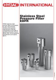
5.3. EXAMPLEGeneral∆p total= ∆p housing+∆p element •viscosity (mm²/s)30 mm²/s∆p housing= to be determined from point 5.1.∆p element= element pressure drop at flow rate Q/n andviscosity 30 mm 2 /s according to point 5.2.n = number of elements according to tableat Point 4, <strong>Filter</strong> specificationsExampleSystem data: <strong>RF</strong>110 with BN3HC element (10 µm)viscosity = 46 mm²/s(ISO VG 46 at 40 °C)Q = 50 l/min⇒ ∆p housing= 0.13 bar (at Q)∆p element= 0.46 bar∆p total= 0.59 barFor ease of calculation, our FSP <strong>Filter</strong> Sizing Programcan be ordered from our website www.hydac.com.6. DIMENSIONS6.1. <strong>RF</strong> 30label with modelcodet4outlethole drilled in the tank coverplate only on version with tankbreather filterd5vent screw or cloggingindicatorinletE 7.116.2/12.04Type b1 b3 d1 d3 1) d5 d6 d7 h1 h2 h3 h4 h5 h6 t1 t2 t4Size 30 71 38 60 G ½ 78 M4 – 86 70 27 8 11 90 14 – 141)threaded connection to ISO 2288
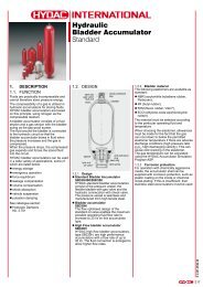
6.2. <strong>RF</strong> 60-240labelwith model codeoutletvent screw orclogging indicatorinletType b1 b3 d1 d3 2) d5 d6 1) h1 h2 h3 h4 h5 h6 t1Size 60 96 55 80 G ¾ 100 M5 63 88 44 6 12 80 17Size 110 96 55 80 G ¾ 100 M5 130 88 44 6 12 145 17Size 160 126 72 106 G 1 ¼ 135 M6 89 108 54 6 12 120 20Size 240 126 72 106 G 1 ¼ 135 M6 150 108 54 6 12 180 201)mounting hole for screw2)threaded connection to ISO 228E 7.116.2/12.049
6.3. <strong>RF</strong> 330-1300Size 330, 660 Size 950, 1300outletoutletlabel withmodel codevent screwor cloggingindicatorlabel withmodel codevent screwor cloggingindicatorinletinletType b1 b3 b5 b6 d1 d3 d4 d5 d6 1) d7Size 330 150 85 – – 135 G2 G2 170 M8 –77.8 42.9 SAE DN 50 (2") M12Size 660 196 110 106.4 61.9 180 SAE DN 80 (3") G3 220 M12 M16Size 950 255 135 120.7 69.5 208 SAE DN 90 (3½") SAE DN 90 (3½") 290 M16 M16Size 1300 255 145 130.2 77.8 208 SAE DN 100 (4") SAE DN 100 (4") 290 M16 M16E 7.116.2/12.04Type h1 h2 h3 h4 h5 h6 t1 t2 t4Size 330 138 131 63 13 12 180 27 – 2723Size 660 243 167 84 13 12 320 – 28 32Size 950 251 198 93 13 12 350 – 22 –Size 1300 332 241 121 13 12 460 – 22 –<strong>Filter</strong> connection for SAE flanges to SAE-J 518c / 3000 psi1)Mounting hole for screw10
6.4. <strong>RF</strong> 2500 - 15000clogging indicatorcover plate lifting devicevent G ½inletdrain G 1top of tankoil leveloutletType Flanged connection h1 h2 h3 h4 h5 h6 b1 b2 d1 d2 d3 d4 d5 No.ofcover platescrews2500 DIN DN 100 732 578 590 992 496 88 395 240 273 360 18 320 G2 8DIN DN 125 505 925 3104000 DIN DN 125 738 501 596 940 496 88 355 282 356 450 18 410 G2 12DIN DN 150 540 995 3885200 DIN DN 125 812 576 670 1030 571 98 382 308 406 510 23 460 G3 8DIN DN 150 615 1085 4166500 DIN DN 150 817 615 680 1110 571 98 470 358 508 620 26 572 G3 8DIN DN 200 720 1210 5357800 DIN DN 200 817 720 680 1210 571 98 535 358 508 620 26 572 G3 8DIN DN 250 800 1315 60515000 DIN DN 250 817 800 709 1360 571 98 712 460 711 840 26 780 G3 8DIN DN 300 866 1460 7777. NOTEThe information in this brochure relates to the operating conditions and applications described. For applications oroperating conditions not described, please contact the relevant technical department.Subject to technical modifications.E 7.116.2/12.0411