Electronic pressure switch
Electronic pressure switch
Electronic pressure switch

Create successful ePaper yourself
Turn your PDF publications into a flip-book with our unique Google optimized e-Paper software.
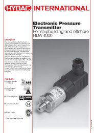
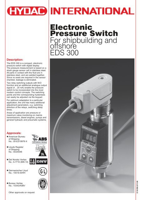
Description:<br />
The EDS 300 is a compact, electronic<br />
<strong>pressure</strong> <strong>switch</strong> with digital display.<br />
The <strong>pressure</strong> measurement is based on a<br />
strain gauge sensor cell in stainless steel.<br />
All parts in contact with the fluid are in<br />
stainless steel, and are welded together.<br />
Since no seals are required in the sensor<br />
chamber, leakage is eliminated.<br />
Two relay <strong>switch</strong>ing outputs with N/O<br />
function and an additional analogue output<br />
signal (4 .. 20 mA) enable the <strong>pressure</strong><br />
<strong>switch</strong> to be incorporated into the most<br />
modern control concepts. The <strong>switch</strong>ing<br />
points and the corresponding hystereses<br />
can easily be adjusted via the keypad.<br />
For optimum adaptation to a particular<br />
application, the unit has many additional<br />
adjustment parameters, e.g. <strong>switch</strong>ing<br />
direction of the relays, <strong>switch</strong>ing delay<br />
times.<br />
Areas of application are <strong>pressure</strong> or<br />
maximum value monitoring on marine<br />
transmissions, diesel engines, pumps and<br />
general hydraulic and pneumatic systems.<br />
<strong>Electronic</strong><br />
Pressure Switch<br />
For shipbuilding and<br />
offshore<br />
EDS 300<br />
Approvals:<br />
• American Bureau<br />
of Shipping<br />
No.: 00-ES19976-X<br />
• Lloyds Register<br />
of Shipping<br />
No.: 00/20048<br />
• Det Norske Veritas<br />
No.: A-7710 (895.10)<br />
• Germanischer Lloyd<br />
No.: 15519-00HH<br />
• Bureau Veritas<br />
No.: 10343/A0BV<br />
Other approvals on request.<br />
E 18.058.2/11.06
Setting options:<br />
All the settings available on the EDS 300<br />
are combined in two easy-to-follow menus.<br />
To prevent unauthorised adjustment of the<br />
unit, a program disable can be activated.<br />
Setting ranges of the<br />
<strong>switch</strong>ing points and/or<br />
<strong>switch</strong>-back hystereses:<br />
Meas. Switching pt. Hysteresis Increrange<br />
ment*<br />
in bar in bar in bar in bar<br />
-1 .. 5 -0.85 .. 5 0.05 .. 5.9 0.05<br />
0 .. 6 0.15 .. 6 0.05 .. 5.9 0.05<br />
0 .. 16 0.3 .. 16 0.1 .. 15.8 0.1<br />
0 .. 40 0.6 .. 40 0.2 .. 39.6 0.2<br />
0 .. 100 1.5 .. 100 0.5 .. 99.0 0.5<br />
0 .. 250 3.0 .. 250 1.0 .. 248 1.0<br />
0 .. 400 6.0 .. 400 2.0 .. 396 2.0<br />
0 .. 600 15.0 .. 600 5.0 .. 590 5.0<br />
Switching point /<br />
<strong>switch</strong>-back point:<br />
The <strong>switch</strong>ing point is defined as being the<br />
<strong>pressure</strong> value, which when reached<br />
(whilst <strong>pressure</strong> is increasing), causes a<br />
change in the <strong>switch</strong>ing output.<br />
This output state is maintained until the<br />
<strong>pressure</strong> falls below the <strong>switch</strong>-back<br />
hysteresis allocated to the <strong>switch</strong>ing point.<br />
The <strong>switch</strong>-back point is determined by the<br />
<strong>switch</strong>-back hysteresis which has been set<br />
(<strong>switch</strong>ing point minus <strong>switch</strong>-back<br />
hysteresis = <strong>switch</strong>-back point).<br />
SP<br />
P<br />
RSP<br />
ON<br />
OFF<br />
HY<br />
t<br />
Pin connections:<br />
PE<br />
SP 1<br />
+<br />
1<br />
SP 2<br />
20 .. 32 V<br />
- 4<br />
3<br />
2<br />
6<br />
5<br />
RL<br />
Analogue<br />
I = 4 .. 20 mA<br />
Meas. Switching pt. Hysteresis Increrange<br />
ment*<br />
in psi in psi in psi in psi<br />
-14 .. 75 -12.5 .. 75.0 -0.5 .. 74.0 0.5<br />
0 .. 150 3 .. 150 1 .. 148 1<br />
0 .. 1000 15 .. 1000 5 .. 990 5<br />
0 .. 3000 45 .. 3000 15 .. 2970 15<br />
0 .. 6000 90 .. 6000 30 .. 5940 30<br />
0 .. 9000 150 .. 9000 50 .. 8900 50<br />
* All ranges given in the table are<br />
adjustable by the increments shown.<br />
SP = <strong>switch</strong>ing point<br />
HY = <strong>switch</strong>-back hysteresis<br />
RSP = <strong>switch</strong>-back point<br />
(<strong>switch</strong>ing point minus <strong>switch</strong>back<br />
hysteresis)<br />
Additional functions:<br />
• Scale of the display range adjustable<br />
(bar, psi)<br />
• Switching direction of the relays<br />
adjustable (pull-in or release when<br />
<strong>switch</strong>ing point is reached)<br />
• Switch-on delay adjustable between<br />
0.00 .. 75 seconds<br />
• Switch-back delay adjustable between<br />
0.00 .. 75 seconds<br />
• Choice of display (actual <strong>pressure</strong>, peak<br />
value, <strong>switch</strong>ing point 1, <strong>switch</strong>ing<br />
point 2, display off)<br />
• Subsequent correction of zero point in<br />
the range ± 3% FS possible<br />
E 18.058.2/11.06<br />
2
Electrical accessories:<br />
ZBE 10<br />
Right-angled connector (6 pole + earth)<br />
to DIN 43651 (not supplied)<br />
Mechanical accessories:<br />
ZBM 14 connection adaptor G¼ female<br />
thread - G¼ A male thread for optimum<br />
alignment of the <strong>pressure</strong> <strong>switch</strong><br />
approx.<br />
Seals:<br />
Female thread: NBR<br />
Male thread: NBR<br />
hex.-SW19<br />
ZBM 310 clamp for wall-mounting the<br />
EDS 300 (materials: polypropylene,<br />
aluminium AlSi12, steel)<br />
Technical specifications:<br />
Input data:<br />
Measuring ranges in bar:<br />
Overload <strong>pressure</strong>s in bar:<br />
Measuring ranges in psi:<br />
Overload <strong>pressure</strong>s in psi:<br />
Burst <strong>pressure</strong>:<br />
Output data:<br />
Accuracy (display, analogue output):<br />
Repeatability:<br />
Temperature drift:<br />
Analogue output:<br />
Switching outputs:<br />
Type:<br />
Switching voltage:<br />
Switching current:<br />
Max. <strong>switch</strong>ing output:<br />
Life expectancy:<br />
Reaction time:<br />
-1 .. 5, 6, 16, 40, 100, 250, 400, 600 bar<br />
15, 15, 32, 80, 200, 500, 800, 900 bar<br />
-14 .. 75, 150, 1000, 3000, 6000, 9000 psi<br />
200, 300, 3000, 7000, 11000, 13000 psi<br />
400 % FS<br />
≤ ±1 % FS max.<br />
≤ ±0.5 % FS max.<br />
≤ ±0.3 % / 10 K zero point max.<br />
≤ ±0.3 % / 10 K range max.<br />
4 .. 20 mA, ohmic resistance ≤ 400 Ω<br />
2 relay contacts (N/O)<br />
10 mV .. 60 V (AC or DC)<br />
0.01 mA .. 1 A<br />
30 W / 30VA<br />
(for inductive load, use varistors)<br />
20 million (min. load)<br />
0.5 million (max. load)<br />
approx. 10 ms<br />
Ambient conditions:<br />
Temperature range of medium: -25 .. + 80 °C<br />
Ambient temperature range: -25 .. + 80 °C<br />
Storage temperature range: -40 .. + 80 °C<br />
Nominal temperature range: -10 .. + 70 °C<br />
mark: EN 61000-6-1, EN 61000-6-2<br />
EN 61000-6-3, EN 61000-6-4<br />
Vibration resistance: 5 .. 25 Hz: 3.2 mm<br />
25 .. 500 Hz: 4 g<br />
Other data:<br />
Supply voltage:<br />
20 .. 32 VDC<br />
Electrical connection:<br />
plug to DIN 43651 (6 pole + earth)<br />
Current consumption:<br />
approx. 100 mA<br />
Protection class: IP 65<br />
Hydraulic connection: G¼ A to DIN 3852,<br />
(torque rating approx. 20 Nm),<br />
SAE 4 female thread<br />
(torque rating approx. 8 Nm)<br />
Parts in contact with fluid:<br />
stainless steel, seal: FPM<br />
Material of housing:<br />
tube: stainless steel<br />
keypad housing: PA6.6 Gf30<br />
Display:<br />
4-digit, 7 segment LED, red<br />
Weight:<br />
approx. 300 g<br />
Note: FS (Full Scale) = relative to the full measuring range<br />
Mounting:<br />
The EDS 300 <strong>pressure</strong> <strong>switch</strong> has a <strong>pressure</strong> connection with a G¼ A male thread<br />
(DIN 3852) or SAE 4 female thread.<br />
It is therefore possible to mount the <strong>pressure</strong> <strong>switch</strong> directly inline or onto a hydraulic<br />
block.<br />
Using the ZBM 14 connection adaptor (only for G1/4 A male thread) ensures that the<br />
display is visible to the user.<br />
When used in critical applications (e.g. strong vibrations or knocks) the EDS 300 must<br />
be mechanically decoupled. A clamp (ZBM 310) is therefore available for wall-mounting.<br />
In this case the <strong>pressure</strong> connection must be by means of a Minimess line.<br />
E 18.058.2/11.06<br />
3
Model code:<br />
EDS 3 X 7- 4 - XXX - S00 (PSI)<br />
Series no.<br />
(determined by manufacturer)<br />
Type of connection, mechanical<br />
4 = G¼ A male thread<br />
5 = SAE 4 female thread<br />
Type of connection, electrical<br />
7 = 6 pole + earth<br />
(connector ZBE 10 is not supplied)<br />
Output<br />
4 = 2 <strong>switch</strong>ing outputs and 1 analogue output<br />
Measuring ranges<br />
bar version, only in conjunction with connection thread G ¼ A:<br />
XXX = 006, 016, 040, 100, 250, 400, 600 with modification no. S00<br />
for -1 .. 5 bar use "006" and modification no. S13<br />
psi version, only in conjunction with connection thread SAE 4:<br />
XXXX= 0150, 1000, 3000, 6000 with modification no. S40<br />
for -14 .. 75 psi use "0089" and modification no. S41<br />
Modification numbers<br />
S00 = bar version (except for -1 .. 5 bar)<br />
S13 = vacuum version -1 .. 5 bar<br />
S40 = psi version (except for -14 .. 75 psi)<br />
S41 = vacuum version -14 .. 75 psi<br />
PSI<br />
= Additional code for psi version<br />
(not required for bar versions)<br />
Accessories available:<br />
For the electrical connection:<br />
ZBE 10 right-angled connector,<br />
(6 pole + earth), DIN 43651<br />
Dimensions:<br />
For the mechanical connection:<br />
ZBM 14 connection adaptor for optimum<br />
alignment of the <strong>pressure</strong> <strong>switch</strong><br />
ZBM 310 clamp for wall-mounting<br />
Connection<br />
DIN 43651<br />
6 pole + earth<br />
hex.<br />
required mounting radius R36<br />
Note:<br />
The information in this brochure relates to the operating conditions and applications described.<br />
For applications or operating conditions not described, please contact the relevant technical<br />
department. Subject to technical modifications.<br />
E 18.058.2/11.06