Oil / Air Cooler Units - Hydac
Oil / Air Cooler Units - Hydac
Oil / Air Cooler Units - Hydac
- No tags were found...

Create successful ePaper yourself
Turn your PDF publications into a flip-book with our unique Google optimized e-Paper software.
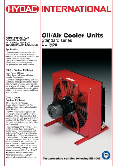
OIL/AIR COOLERDESCRIPTIONGENERALIn hydraulic systems energy istransformed and transmitted. During thistransformation and transmission lossesoccur, i.e. mechanical and hydraulicenergy is converted into heat. It is thefunction of the cooler to dissipate thisheat.ADVANTAGES OF THE OIL/AIRCOOLERS:• Environmentally friendly:exchange between air and oil notpossible• For commissioning only electricalenergy is required• Low operating costs, no additionalcooling circuit necessary for thecooling medium, i.e. airCONSTRUCTION FOR OK EL1-11<strong>Oil</strong>/air cooler units consist of the (1)metal housing, (2) motor, (3) axial fanand (4) heat exchanger. The oilconnections are external.OK-EL1OK-EL2-3OK-EL1OK-EL2-3OK-EL7,8OK-EL4,5,6,9,10,11OK-EL4-11Example2
CONSTRUCTION FOROKA & OKAF EL4-6OKA-EL4,5,6OKA-EL4,5,6OKA-EL4,5,6<strong>Oil</strong>/air cooler units consists of the metalhousing (1), motor (2), axial fan (3) andheat exchanger (4), and low noise feedpump (5) with excellent suctionperformance. The oil connections areexternal.OKAF-EL4,5,6<strong>Oil</strong>/air cooler units consist of the metalhousing (1), motor (2), axial fan (3), heatexchanger (4), low noise feed pump (5)with excellent suction performance andfilter (6). The oil connections areexternal, together with access to thefilter element for cleaning and changing.The filters are fitted with visual cloggingindicators, as standard.OKAF-EL4,5,6OKAF-EL4,5,6Example3
CONSTRUCTION FOROKA & OKAF EL7-11OKA-EL7-11OKA-EL7-11OKA-EL7-11<strong>Oil</strong>/air cooler units consist of the metalhousing (1), motor (2), axial fan (3), heatexchanger (4), and low noise feed pump(5) with excellent suction performance.The oil connections are external.OKAF-EL7-11<strong>Oil</strong>/air cooler units consist of the metalhousing (1), motor (2), axial fan (3), heatexchanger (4), and low noise feed pump(5) with excellent suction performanceand filter (6). The oil connections areexternal, together with access to thefilter element for cleaning and changing.The filters are fitted with visual cloggingindicators, as standard.OKAF-EL7-11OKAF-EL7-11Example4
COOLERSELECTIONP VP 01Vρ oilC oil∆TtT 1T 3Designation:= Power loss [kW]= Specific cooling capacity [kW/°C]= Tank contents [l]= Density of the oil [kg/l]for mineral oil: 0.915 kg/l= Specific heat capacity [kJ/kg°C]for mineral oil 1.88 kJ/kg°C= Temperature increase in thesystem [°C]= Operating time [min]= Desired oil temperature [°C]= Ambient temperature [°C]Example 1:Measurement of the power losson existing units and machinery.For this method the temperatureincrease of the oil is measuredover a certain period. The powerloss can be calculated from thetemperature increase.Parameters:The oil temperature increasesfrom 20 °C to 45 °C over15 minutes.The tank contains 100 l.Heat to be dissipated:P v= ∆T × c oil × ρ oil × V [kW]t × 60P vP 01=P 01== 25 × 1.88 × 0.915 × 100 = 4.78 [kW]t × 60<strong>Cooler</strong> selection:– Desired oil temperature: 60 °C– Ambient temperature (air): 30 °CP vT 1- T 34.7860 - 30[kW/°C]= 0.159 [kW/°C]A 10% safety margin isrecommended to allow forelement contamination, andtherefore the specific power is:P 01× 1.1 = 0.175 kW/°CThe power loss 0.175 kW/°C mustbe dissipated by an oil cooler.Suggestion:–<strong>Cooler</strong> OK-EL2H,P 01= 0.18 kW/°C at 80 l/min.Example 2:The power loss can also beestimated: With unrestricted flowapprox. 15 to 20% of the drivepower. With restricted flow up to30% of the drive power.1. TECHNICAL DETAILS1.1. TABLE OF TECHNICAL SPECIFICATIONS FOR SIZES 1 TO 6Type of coolerDisplacement [cm³/U]<strong>Oil</strong> flow [l/min]N° of poles [-] / size[-]Motor capacity [kW] at 50 HzOK-EL1H – *120 ** 0.04 60 16 130 2000 – 7OK-EL2S – *180 4/63 0.18 64 16 130 2000 – 13OK-EL2H – *180 2/63 0.25 80 16 130 2000 – 13OK-EL3S – *180 4/63 0.18 66 16 130 2000 – 17OK-EL3H – *180 2/71 0.55 85 16 130 2000 – 17OK-EL4L – *200 6/71 0.25 63 16 130 2000 – 31OK-EL4S – *200 4/71 0.37 72 16 130 2000 – 31OKA-EL4L 28-40 24/34 6/90 1.1 68 6 80 350 – 34OKA-EL4S 28-40 36/52 4/90 1.8 75 6 80 350 – 34OKAF-EL4L 28-40 24/34 6/90 1.1 68 6 80 350 LPF 160 41OKAF-EL4S 28-40 36/52 4/90 1.8 75 6 80 350 LPF 160 41OK-EL5L – *250 6/80 0.37 65 16 130 2000 – 38OK-EL5S – *250 4/90 1.1 75 16 130 2000 – 38OKA-EL5L 28-40 24/34 6/90 1.1 70 6 80 350 – 41OKA-EL5S 28-40 36/52 4/90 1.8 80 6 80 350 – 41OKAF-EL5L 28-40 24/34 6/90 1.1 70 6 80 350 LPF 160 48OKAF-EL5S 28-40 36/52 4/90 1.8 80 6 80 350 LPF 160 48OK-EL6L – *250 6/80 0.37 67 16 130 2000 – 43OK-EL6S – *250 4/90 1.1 77 16 130 2000 – 47OKA-EL6L 28-40 24/34 6/90 1.1 70 6 80 350 – 50OKA-EL6S 28-40 36/52 4/90 1.8 81 6 80 350 – 50OKAF-EL6L 28-40 24/34 6/90 1.1 70 6 80 350 LPF 160 57OKAF-EL6S 28-40 36/52 4/90 1.8 81 6 80 350 LPF 160 57* :max oil flow**:electrical fans IP20– Suction vacuum at pump inlet max -0.4 bar.– For direction of fan rotation, see arrow on cooler housing.– Electric vent drive: axial drive with forward flow through cooler element (sucking).– Cooling fluid: mineral oil to DIN 51524; for other fluids,please contact our sales/technical department.– Three-phase motors IP55, conforming to CE norm.– The noise levels are only a guide as acoustic properties vary and dependon the characteristics of the room, connections, viscosity and resonance.Warning!When operating a cooler in situations where the difference in temperature betweenambient air and inlet oil exceed 50 Deg. Celsius, care must be taken to avoid cyclingof the fan at full speed/air flow as this can cause rapid change in materialtemperature of element and may result in significant reduction in lifetime or directdamage to the element through thermal stress.Please contact your <strong>Hydac</strong> Branch or distributor for speed control solutions.Noise level (1m distance) [dB(A)] at 50 HzMax. operating pressure [bar]Max. oil temperature [°C]Max. viscosity [mm 2 /s]Size of filter [-]Weight [kg]5
1.3. HYDRAULIC DETAILS1.3.1 Cooling capacity:depending on oil flow and the temperature differential ∆T between the oil inlet and air inletFor calculations with low ∆T values (i.e. below 10 °C), please contact our technical support staff.OK EL1-6Tolerance: ± 5%Heat dissipation at ∆T = 40 °C [kW]302826242220181614121086420EL1H00 20 40 60 80 100 120 140 160 180 200 220 240 260<strong>Oil</strong> flow [l/min]EL3HEL3SEL2HEL2SEL4SEL4LEL6LEL6SEL5SEL5L0.750.70.650.60.550.50.450.40.350.30.250.20.150.10.05Specific heat dissipation [kW/°C] *OK EL7-11Tolerance: ± 5%1203110100EL11L2.752.5Heat dissipation at ∆T = 40 °C [kW]90807060504030EL8SEL7SEL8LEL7LEL11LLEL10LEL10LLEL9LEL9LL2.2521.751.51.2510.75Specific heat dissipation [kW/°C] *200.5100.25000 30 60 90 120 150 180 210 240 270 300 330 360 390 420<strong>Oil</strong> flow [l/min]* Values measured at ∆T = 40 °C, may vary at lower ∆T values7
1.3.2 Pressure differential ∆p:measured at 30 mm²/s using mineral oilPressure drop curves OK EL1-6Tolerance: ± 5%3.53.0EL1EL3EL2Pressure drop at 30 mm²/s [bar]2.52.01.51.0EL4EL5EL60.50.00 30 60 90 120 150 180 210 240 270 300<strong>Oil</strong> flow [l/min]Pressure drop curves OK EL7-11Tolerance: ± 5%21.81.6EL7EL8EL11Pressure drop at 30 mm²/s [bar]1.41.210.80.60.40.20EL10EL90 30 60 90 120 150 180 210 240 270 300 330 360 390 420<strong>Oil</strong> flow [l/min]For other viscosities the result must be multiplied by KViscosity (mm²/s) 10 15 22 30 46 68 100 150Factor K 0.35 0.5 0.75 1 1.4 1.9 2.5 3.58
2. MODEL TYPE(also order example)OKAF-EL4S / 40 / 3 . 0 / B / M / A / LPF160 / 4 / 1 / IBTType of coolerOK-EL = <strong>Oil</strong>/air coolerOKA-EL = <strong>Oil</strong>/air cooler with built-in feed pumpOKAF-EL = <strong>Oil</strong>/air cooler with built-in feed pump and filterSize / motor speed1-11 = See hydraulic details 1.3.LL = 8 pl (750 min -1 )L = 6 pl (1000 min -1 )S = 4 pl (1500 min -1 )H = 2 pl (3000 min -1 )Displacement cm³/rev28, 40 = (OKA/OKAF-EL4 -> EL6, see technical details 1.1.)40, 58, 69 = (OKA/OKAF-EL8 -> EL11, see technical details 1.2.)Type code and modification numberFor the latest version of each cooler, please see the table in our internet site.Clogging indicators (only OKAF)A = Without clogging indicatorB = With visual indicator (*)C = With electrical indicatorD = With electrical and optical indicatorFluidsM = Mineral oil to DIN 51524Other fluids on requestMotor voltageA = Standard voltages and frequencies for three–phase motor50 Hz: 380 - 420 V (Y) / 220-240 V (∆)60 Hz: 440 - 480 V (Y) / 254-277 V (∆)Except for EL1, for which the standard voltage is 220-240 V, 50/60Hz, single phaseOther special voltages and frequencies on request and clearly writtenSize of filter (only OKAF)OKAF-EL4-6 = LPF160OKAF-EL7-11 = LPF280Filtration rating in micron, Viscosity up to 80 mm²/s (only OKAF)8 = 5 µm Betamicron ® -3-N (5 BN3HC)4 = 10 µm Betamicron ® -3-N (10 BN3HC) *5 = 20 µm Betamicron ® -3-N (20 BN3HC)Paint1 = RAL 5009 (Standard)Other paint on request and clearly writtenAccessoriesAITF48 = Thermostat (fixed)IBP = Heat exchanger with integrated bypass valveIBT = Heat exchanger with integrated thermo-bypass valveGP = Vibration absorber* standard for OKAF unless otherwise specified.9
3. DIMENSIONS3.1. OK-EL13.2. OK-EL2-6PlugPlug3.3. OK-EL7-8(4x) slot FPlug3.4. OK-EL9-11PlugA1 B C1 D1 D2 D3 E1 E2 E3 F W1 W2 Z1 Z3±10 ±25 ±10 ±2 ±2 ±2 ±5 ±5 ±5 Ø/slot Min.* Min.*OK–EL1 H 355 – 200 255 150 295 289 41 88 9 150 100 G¾" –OK–EL2 S,H 355 400 330 255 160 295 289 41 58 9 500 200 G¾" –OK–EL3 S,H 455 420 380 255 290 295 389 41 58 9 800 300 G¾" –OK–EL4 L,S 520 527 485 410 425 450 439 51 104 9 1200 400 G1" –OK–EL5 L,S 562 580 542 410 482 450 439 72 94 9 1500 500 G1" –OK–EL6 L,S 640 600 584 410 482 450 500 80 74 9 1800 600 G1 ¼" M22x1.5OK–EL7 L,S 726 612 706 410 560 450 600 73 74 9x20 1200 600 G1 ¼" M22x1.5OK–EL8 L,S 726 612 706 410 560 450 630 58 74 9x20 1200 600 G1 ¼" M22x1.5OK–EL9 L 880 709 790 750 700 790 760 75 116 12 2500 900 G1 ½" M22x1.5OK–EL10 L 1030 758 930 750 700 790 910 75 116 12 2800 900 G1 ½" M22x1.5OK–EL11 L 1180 804 1050 750 700 790 1060 75 116 12 3000 1000 G1 ½" M22x1.5* for smaller distances please contact our technical office10
3.5. OKA/OKAF-EL4-63.6. OKAF-EL7-8Plug(4x)slot FPlug3.7. OKA/OKAF-EL9-11(4x)slot FA1 B C1 C2 D1 D2 D3 E1 E2 E3 F W1 W2 Z1 Z2(3x) Z3±10 ±25 ±10 ±25 ±2 ±2 ±2 ±5 ±5 ±5 Ø/slot Min.* Min.* (IN)OKA–EL4 L,S 520 690 485 578 410 425 450 439 51 104 9 1200 400 G1 ¼" G 1" –OKA–EL5 L,S 562 700 542 653 410 482 450 439 72 94 9 1500 500 G1 ¼" G 1" –OKA–EL6 L,S 640 720 584 709 410 482 450 500 80 74 9 1800 600 G1 ¼" G1 ¼" M22x1.5OKAF–EL4 L,S 520 690 485 631 410 425 450 439 51 104 9 1200 400 G1 ¼" G 1" –OKAF–EL5 L,S 562 700 542 688 410 482 450 439 72 94 9 1500 500 G1 ¼" G 1" –OKAF–EL6 L,S 640 720 584 725 410 482 450 500 80 74 9 1800 600 G1 ¼" G1 ¼" M22x1.5OKA–EL7 L,S 736 612 706 775 560 560 600 600 83 74 9x20 1200 600 G 2" G1 ¼" M22x1.5OKA–EL8 L,S 736 612 706 815 560 560 600 630 68 74 9x20 1200 600 G 2" G1 ¼" M22x1.5OKA–EL9 L 880 709 790 910 830 700 870 760 75 116 12 2500 900 G 2" G1 ½" M22x1.5OKA–EL10 L 1030 758 930 1050 830 700 870 910 75 116 12 2800 900 G 2" G1 ½" M22x1.5OKA–EL11 L 1180 804 1050 1150 830 700 870 1060 75 116 12 3000 1000 G 2" G1 ½" M22x1.5OKAF–EL7 L,S 736 612 706 825 560 560 600 600 83 74 9x20 1200 600 G 2" G1 ¼" M22x1.5OKAF–EL8 L,S 736 612 706 846 560 560 600 630 68 74 9x20 1200 600 G 2" G1 ¼" M22x1.5OKAF–EL9 L 880 709 790 936 830 700 870 760 75 116 12 2500 900 G 2" G1 ½" M22x1.5OKAF–EL10 L 1030 758 930 1071 830 700 870 910 75 116 12 2800 900 G 2" G1 ½" M22x1.5OKAF–EL11 L 1180 804 1050 1191 830 700 870 1060 75 116 12 3000 1000 G 2" G1 ½" M22x1.5* for smaller distances please contact our technical office4. CERTIFICATION FOLLOWING EN 1048<strong>Hydac</strong> SA design and manufacture high quality coolersthat are tested and certified to give reliable andrepeatable high performance. To ensure theperformance is accurate, testing in compliance with arecognized international test standard is the bestsolution. For air/liquid coolers this is EN1048.<strong>Hydac</strong> SA test procedure complies withthe requirements of EN 1048 and boththe procedure and test equipment areindependently inspected and certifiedby TÜV SÜDDEUTSCHLAND.The cooler performance details inthis brochure have been tested following EN 1048.5. NOTEThe information in this brochure relates to the operatingconditions and applications described.For applications or operating conditions not described,please contact the relevant technical department.Subject to technical modifications.11