analysis of steel-concrete composite beam-to ... - CCVI Information
analysis of steel-concrete composite beam-to ... - CCVI Information
analysis of steel-concrete composite beam-to ... - CCVI Information

Create successful ePaper yourself
Turn your PDF publications into a flip-book with our unique Google optimized e-Paper software.
ANALYSIS OF STEEL-CONCRETE COMPOSITE BEAM-TO-COLUMN<br />
JOINTS: BOLTED SOLUTIONS<br />
Oreste S. Bursi<br />
Department <strong>of</strong> Mechanical and Structural Engineering, University <strong>of</strong> Tren<strong>to</strong><br />
Tren<strong>to</strong>, Italy<br />
oreste.bursi@ing.unitn.it<br />
Fabio Ferrario<br />
Department <strong>of</strong> Mechanical and Structural Engineering, University <strong>of</strong> Tren<strong>to</strong><br />
Tren<strong>to</strong>, Italy<br />
fabio.ferrario@ing.unitn.it<br />
Raffaele Pucinotti<br />
Department <strong>of</strong> Mechanics and Materials, Mediterranean University <strong>of</strong> Reggio Calabria<br />
Reggio Calabria, Italy<br />
raffaele.pucinotti@unirc.it<br />
Riccardo Zandonini<br />
Department <strong>of</strong> Mechanical and Structural Engineering, University <strong>of</strong> Tren<strong>to</strong><br />
Tren<strong>to</strong>, Italy<br />
riccardo.zandonini@ing.unitn.it<br />
ABSTRACT<br />
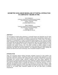
In this paper, a multi-objective advanced design methodology is proposed for <strong>steel</strong>-<strong>concrete</strong><br />
<strong>composite</strong> moment-resisting frames. The research activity mainly focused on the design <strong>of</strong> the<br />
<strong>beam</strong>-<strong>to</strong>-column joints under seismic-induced fire loading <strong>to</strong>gether with the definition <strong>of</strong><br />
adequate structural details for <strong>composite</strong> columns. Thermal analyses <strong>of</strong> cross sections were<br />
performed in order <strong>to</strong> obtain internal temperature distribution; structural analyses were then<br />
performed on the whole frame <strong>to</strong> assess the global behavior under the combined action <strong>of</strong> static<br />
and fire loadings. Besides, results <strong>of</strong> numerical analyses were used in order <strong>to</strong> derive<br />
information about the mechanical and numerical behavior <strong>of</strong> joints. In this paper the<br />
experimental program carried out on four <strong>beam</strong>-<strong>to</strong>-column joint specimens are described and<br />
experimental results are presented and discussed <strong>to</strong>gether with the outcomes <strong>of</strong> numerical<br />
simulations. Experimental tests demonstrated the adequacy <strong>of</strong> the seismic design. Numerical<br />
simulations showed a satisfac<strong>to</strong>ry performance <strong>of</strong> joints under seismic-induced fire loading.<br />
INTRODUCTION<br />
Steel-<strong>concrete</strong> <strong>composite</strong> structures are becoming increasingly popular around the world due <strong>to</strong><br />
the favorable stiffness, strength and ductility performance <strong>of</strong> <strong>composite</strong> systems under seismic<br />
loading, and also due <strong>to</strong> the speed and ease <strong>of</strong> erection. Moreover, such structures exhibit<br />
better fire resistance characteristics compared <strong>to</strong> bare <strong>steel</strong> structures. Considering the high
probability <strong>of</strong> a fire after a seismic event, the use <strong>of</strong> <strong>steel</strong>–<strong>concrete</strong> <strong>composite</strong> structures in<br />
seismic areas, potentially represents a fairly effective design solution. In fact, the adoption <strong>of</strong><br />
such a solution is in general more efficient from both a structural and a constructional viewpoint<br />
when compared <strong>to</strong> bare <strong>steel</strong> structures. The benefit increases, if the high probability that an<br />
earthquake and a fire can occur in sequence. In current Eurocodes for structural design,<br />
seismic and fire safety are accounted for separately, and no sequence <strong>of</strong> seismic and fire<br />
loading is taken in<strong>to</strong> account. In reality, the risk <strong>of</strong> loss <strong>of</strong> life increases if a fire occurs in a<br />
building after an earthquake. In the Kobe Earthquake (1995) many people died due <strong>to</strong> the<br />
collapse <strong>of</strong> buildings exposed <strong>to</strong> a fire that followed an earthquake; in fact, large sections <strong>of</strong> the<br />
city burned, greatly contributing <strong>to</strong> the loss <strong>of</strong> lives. It is obvious therefore that seismic-induced<br />
fire is a design scenario that should be properly addressed in any performance-based seismic<br />
design. In this situation the traditional single-objective design is not adequate, and a multiobjective<br />
advanced design has <strong>to</strong> be adopted. This enables a proper account <strong>of</strong>: (i) seismic<br />
safety with regard <strong>to</strong> accidental actions; (ii) fire safety with regard <strong>to</strong> accidental actions (iii) fire<br />
safety on a structure characterized by stiffness deterioration and strength degradation due <strong>to</strong><br />
seismic actions. As a result, the fire design applied <strong>to</strong> a structure with reduced capacity due <strong>to</strong><br />
seismic damage will permit simultaneous fulfillment <strong>of</strong> the requirements associated with<br />
structural, seismic and fire safety ,and with structural fire safety and structural seismic safety<br />
separately taken as accidental actions. In order <strong>to</strong> characterize the seismic behaviour <strong>of</strong><br />
<strong>composite</strong> joints, a research project has been carried out by the University <strong>of</strong> Tren<strong>to</strong> with the<br />
objective <strong>of</strong> developing a design procedure for <strong>composite</strong> joints under the ‘combined’ action <strong>of</strong><br />
earthquake and post-earthquake fire. The research activity was mainly concerned with the<br />
design <strong>of</strong> bolted <strong>beam</strong>-<strong>to</strong>-column joints with CFT columns with circular hollow <strong>steel</strong> sections.<br />
This solution derives from a parent welded design solution developed in an European project<br />
(Bursi et al. 2006) and is aimed at ensuring easiness <strong>of</strong> assembly and avoiding the problems<br />
related with on site welding. The results <strong>of</strong> the experimental programme devoted <strong>to</strong> the<br />
evaluation <strong>of</strong> the cyclic behavior <strong>of</strong> <strong>beam</strong>-<strong>to</strong>-column bolted joints are reported in the following. In<br />
order <strong>to</strong> better understand the activation <strong>of</strong> all the transfer mechanisms proposed in the<br />
Eurocode 8 (UNI EN 1998-1, 2005), a numerical finite element (FE) model <strong>of</strong> the slab has been<br />
developed, <strong>to</strong>gether with FE model <strong>of</strong> the joint under fire.<br />
SEISMIC AND FIRE DESIGN OF REFERENCE FRAMES<br />
A reference <strong>composite</strong> <strong>steel</strong>-<strong>concrete</strong> <strong>of</strong>fice-building was considered, made up <strong>of</strong> three five<br />
s<strong>to</strong>reys moment resisting frames, placed at the distance <strong>of</strong> 7.5 m each in the longitudinal<br />
direction and braced in the transverse direction. The s<strong>to</strong>rey height was equal <strong>to</strong> 3.5 m. Two<br />
moment resisting frames, having the same structural typology but different slab systems, were<br />
analyzed: i) a <strong>composite</strong> <strong>steel</strong>-<strong>concrete</strong> slab with structural pr<strong>of</strong>iled ribbed <strong>steel</strong> sheeting; ii) a<br />
<strong>concrete</strong> slab composed <strong>of</strong> electro-welded lattice girders.<br />
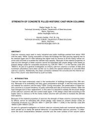
Since the two slab systems had different load bearing capacities, a different distance between<br />
the secondary <strong>beam</strong>s was adopted for the two solutions. The distance slightly affected the<br />
frame geometry. The first solution (<strong>steel</strong> sheeting slab), is depicted in Figure 1a while the<br />
second one, with the slab on prefabricated lattice elements, is shown in Figure 1b. The<br />
elevation is shown in Figure 1c (Bursi et. al 2008). Two different types <strong>of</strong> <strong>composite</strong> <strong>beam</strong>s were<br />
hence designed according <strong>to</strong> Eurocode 4 (UNI EN 1994-1-1, 2005); the <strong>steel</strong> section was<br />
maintained in both cases an IPE400 <strong>of</strong> <strong>steel</strong> grade S355. The slab, 150 mm deep, was<br />
designed in accordance with the relevant specifications <strong>of</strong> Section 9 <strong>of</strong> Eurocode; moreover<br />
design procedure indicated by the producer <strong>of</strong> the prefabricated lattice elements was followed in<br />
the second case. All connections between the <strong>steel</strong> <strong>beam</strong> and the slab were made by Nelson<br />
19 mm stud connec<strong>to</strong>rs made <strong>of</strong> <strong>steel</strong> with an ultimate tensile strength f u =450 MPa.
a) b) c)<br />
Figure 1 - The configuration <strong>of</strong> the building and the longitudinal five-s<strong>to</strong>rey MR Frame; slab with<br />
a) pr<strong>of</strong>iled ribbed <strong>steel</strong> sheeting; b) slab with prefabricated lattice girder; c) elevation<br />
The frames were designed <strong>to</strong> have a dissipative structural behavior according <strong>to</strong> Eurocode 8<br />
(UNI EN 1998-1, 2005). In detail two following structural types were considered.<br />
1. Moment Resisting Frames: in which dissipative zones were mainly located <strong>to</strong> the end <strong>of</strong> the<br />
<strong>beam</strong>s, in the vicinity <strong>of</strong> <strong>beam</strong>-<strong>to</strong>-column connections, where plastic hinges could develop<br />
(UNI EN 1998-1, 2005, 7.1.2 b);<br />
2. Concentrically braced frames: in which the horizontal forces were mainly resisted by<br />
members subjected <strong>to</strong> axial forces with dissipative zones located on the tension diagonals<br />
only (UNI EN 1998-1, 2005, 7.1.2 c).<br />
The effective width <strong>of</strong> the slab in <strong>composite</strong> <strong>beam</strong>s was determined according <strong>to</strong> Eurocode 4<br />
(UNI EN 1994-1-1, 2005, 5.4.1.2) for static and fire analyses, and <strong>to</strong> Eurocode 8 (UNI EN 1998-<br />
1, 2005, 7.6.3) for seismic analyses. Beam-<strong>to</strong>-column connections resulted <strong>to</strong> be rigid according<br />
<strong>to</strong> Eurocode criterion (UNI EN 1994-1-1, 5.1.2). The design <strong>of</strong> structural elements were<br />
performed considering static and seismic design situations. Moreover, numerical simulations on<br />
two-dimensional (2D) frames, were first performed by means <strong>of</strong> the SAFIR program (Franssen<br />
J.-M. 2000), in order <strong>to</strong> study different fire scenarios acting in the reference buildings and <strong>to</strong><br />
evaluate the performance <strong>of</strong> different elements, i.e. <strong>composite</strong> <strong>beam</strong>s, <strong>composite</strong> columns, and<br />
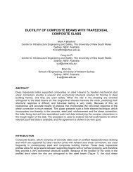
<strong>beam</strong>-<strong>to</strong>-column joints, under fire load for different times <strong>of</strong> exposure <strong>to</strong> fire. Five fire scenarios<br />
were considered. In the first one (FS1), fire acted only in<strong>to</strong> a span in the first floor as illustrated<br />
in Figure 3a.<br />
a) FS1 b) FS2 c) FS3 d) FS4 e) FS5<br />
Figure 3 - Fire scenarios considered in thermal <strong>analysis</strong><br />
In the second one (FS2), fire acted on the whole first floor; this means that the first level<br />
columns and the first level <strong>beam</strong>s were heated. In the third one (FS3), fire acted only in<strong>to</strong> a<br />
span in the last floor. In the fourth one (FS4), fire acted on the whole fifth floor. Finally, in the<br />
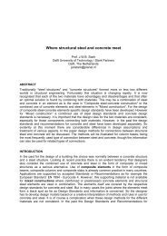
fifth one (FS5) fire acted on the whole frame. The fire load followed the ISO 834 fire law. Figure<br />
4 shows the evolution <strong>of</strong> the bending moment and <strong>of</strong> the axial force as a function <strong>of</strong> time at<br />
various locations in the FE model for the case FS1. In detail the bending moment in the column
C shows an inversion in the sign when axial forces in the <strong>beam</strong>s changes sign <strong>to</strong>o. In fact, the<br />
increase <strong>of</strong> the temperature cause first an increment <strong>of</strong> axial load in the <strong>beam</strong> (compression)<br />
until <strong>to</strong> about 18 min owing the presence <strong>of</strong> the column restraint. Afterwards, the reduction <strong>of</strong><br />
stiffness <strong>of</strong> columns subject <strong>to</strong> fire prevails and the axial force in the <strong>beam</strong> turns <strong>to</strong> tension,<br />
being similar <strong>to</strong> a “catenary” structure (with large displacement and deflection). The elongation<br />
<strong>of</strong> the <strong>beam</strong> due <strong>to</strong> increase in temperature and the different “restraint” effect <strong>of</strong>fered by the<br />
column also causes a reversal <strong>of</strong> the sign <strong>of</strong> bending moment at mid-span <strong>of</strong> the <strong>beam</strong> which<br />
from sagging becomes hogging and then sagging again. The results <strong>of</strong> the <strong>analysis</strong> shows that<br />
the frame collapses because <strong>of</strong> the formation <strong>of</strong> a <strong>beam</strong> mechanism in the longest span<br />
involving the formation <strong>of</strong> three plastic hinges located at mid-span and at both <strong>beam</strong> ends near<br />
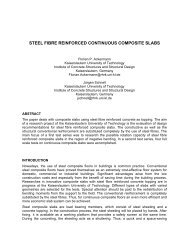
supports. Figure 5 shows column temperature distributions in the fire case FS1; it is possible <strong>to</strong><br />
notice that the <strong>steel</strong> tubular section <strong>of</strong>fers a practically negligible protection <strong>to</strong> internal <strong>concrete</strong>;<br />
therefore temperatures <strong>of</strong> <strong>steel</strong> elements directly exposed <strong>to</strong> fire are equal <strong>to</strong> that <strong>of</strong> the external<br />
atmosphere.<br />
1000.00<br />
Column C - first floor<br />
500.00<br />
M (kNm)<br />
0.00<br />
0 5 10 15 20 25 30<br />
-500.00<br />
Axial Load (kN)<br />
600<br />
400<br />
200<br />
-400<br />
-600<br />
-800<br />
151 155 160 161 165 170<br />
A<br />
B<br />
Beams A & B - first Floor<br />
110<br />
C<br />
101<br />
0<br />
-200 0 5 10 15 20 25 30<br />
compressione<br />
Time (min)<br />
elem. 165<br />
elem. 155<br />
M (kNm)<br />
-1000.00<br />
-1500.00<br />
400.00<br />
0.00<br />
-400.00<br />
-800.00<br />
Time (min)<br />
Beam B - first floor<br />
elem. 101<br />
elem. 110<br />
0 5 10 15 20 25 30<br />
Time (min)<br />
elem. 161<br />
elem. 165<br />
elem. 170<br />
Figure 4 – Fire Case FS1: Bending Moment and Axial Load in <strong>beam</strong>s and columns <strong>of</strong> the first<br />
s<strong>to</strong>rey<br />
10’ 30’ 40’<br />
Figure 5 - Temperature distributions inside the column at different time. Fire Case FS1<br />
The thermal distribution, for the <strong>composite</strong> slab with <strong>steel</strong> sheeting, evaluated after 10 min, 30<br />
min and 40 min <strong>of</strong> ISO fire, by means <strong>of</strong> the thermal FE model created by SAFIR are presented<br />
in Figure 6, while Figure 7 shows the thermal distribution for the case <strong>of</strong> <strong>composite</strong> slab with<br />
prefabricated slab. As expected, the temperature increment was higher in the <strong>composite</strong> slab<br />
with <strong>steel</strong> sheeting than in the slab with prefabricated R.C. elements. As a result, the moment<br />
resistance <strong>of</strong> the former slab was lower than in the latter owing <strong>to</strong> the higher reduction in<br />
materials strength.
10’ 30’ 40’<br />
Figure 6 – Fire case FS1. Evolution <strong>of</strong> the temperature distribution inside <strong>beam</strong> B with a <strong>steel</strong><br />
sheeting <strong>composite</strong> slab.<br />
10’ 30’ 40’<br />
Figure 7 – Fire case FS1. Evolution <strong>of</strong> temperature distribution inside <strong>beam</strong> B with prefabricated<br />
elements<br />
BEAM-TO-COLUMN JOINTS DESIGN<br />
The joint design aimed at ensuring <strong>to</strong> the joint between the column and the <strong>beam</strong> an<br />
overstrength with respect <strong>to</strong> the <strong>beam</strong>. The proposed bolted solution derives from a parent<br />
welded design (Bursi et. al 2008), and was conceived <strong>to</strong> guarantee easiness <strong>of</strong> assembly and <strong>to</strong><br />
avoid problems related <strong>to</strong> welding on site. The joint is comprised <strong>of</strong> two horizontal diaphragm<br />
plates and a vertical through-column plate attached on the tube by groove welds as indicated in<br />
Figure 8.<br />
2x HORIZONTAL PLATES<br />
VERTICAL PLATE<br />
23°<br />
23°<br />
23°<br />
23°<br />
23°<br />
16 168 16<br />
= 320 x 1094 x 14<br />
1094<br />
36 75 75 75 572 75 75 75 36<br />
2,3<br />
18<br />
18<br />
14<br />
R228,5<br />
18<br />
= 660 x 1304 x 16<br />
124 36<br />
Column<br />
1304<br />
320<br />
124<br />
660<br />
200 230<br />
502 300 502<br />
= 320 x 1094 x 14<br />
66 66 66 66 6636<br />
46 108 46<br />
36<br />
Section A-A<br />
1304<br />
300<br />
A<br />
A<br />
A<br />
a=8 L=320<br />
a=8 L=320<br />
A<br />
230<br />
= 660 x 1304 x 16<br />
660<br />
14<br />
R228,5<br />
4,3<br />
18<br />
166<br />
17<br />
17<br />
a=8 L=1475<br />
a=8 L=320 a=8 L=320<br />
Figure 8 - Steel-<strong>concrete</strong> <strong>composite</strong> <strong>beam</strong>-<strong>to</strong>-column joint: a) horizontal and vertical plates; b)<br />
Nelson studs in columns<br />
The flanges and the web <strong>of</strong> each <strong>beam</strong> were connected <strong>to</strong> the horizontal plates and the vertical<br />
plate by two and three rows <strong>of</strong> bolts M27 10.9, respectively. A part the slab type, joints differed<br />
owing <strong>to</strong> the presence <strong>of</strong> strengthening plates with holes required by Eurocode 8 <strong>to</strong> avoid brittle<br />
fracture in net sections <strong>of</strong> bolted joints. Thus specimens JB-P1 and JB-S1, see table 1, where<br />
endowed with extra plates; whereas JB-P2 and JB-S2 had no plates being <strong>beam</strong>-<strong>to</strong>-column<br />
joints not dissipative. Beam-<strong>to</strong>-column joint design was developed using the component<br />
method. The joint was simulated by a series <strong>of</strong> different components in agreement with<br />
Eurocode 3 par 1-8 and Eurocode 8 (UNI EN 1993-1-8, 2005, UNI EN 1998-1, 2005), achieving<br />
the necessary overstrength <strong>to</strong> the joint in respect <strong>to</strong> the connected <strong>composite</strong> <strong>beam</strong>s.
Stiffness and strength <strong>of</strong> complex components, like <strong>to</strong>p and bot<strong>to</strong>m plates or <strong>concrete</strong> slab in<br />
compression, were defined by means <strong>of</strong> refined Finite Element (FE) models <strong>of</strong> the joint including<br />
friction between the slab and the column was developed. Depending on the level <strong>of</strong> friction, the<br />
distribution <strong>of</strong> the compression forces in the slab under sagging bending moment was found <strong>to</strong><br />
be different: localized in front <strong>of</strong> the column for a friction coefficient equal <strong>to</strong> 0,35 as indicated in<br />
Figure 9a; while it spreads over a more extended portion <strong>of</strong> the slab for increasing values <strong>of</strong> the<br />
friction coefficient. In detail, the diffusion angle becomes greater than 80 degrees for a friction<br />
coefficient <strong>of</strong> about 1. The results show that, in order <strong>to</strong> activate the transfer mechanisms<br />
proposed in the Eurocode 8 (UNI EN 1998-1, 2005), i.e. Mechanism 1 front mechanism and<br />
Mechanism 2 strut and tie mechanism, it is necessary <strong>to</strong> increase the level <strong>of</strong> friction between<br />
the <strong>concrete</strong> slab and the <strong>composite</strong> column. As a result, Nelson 19 mm stud connec<strong>to</strong>rs<br />
welded around the column were used in the tested specimens as indicated in Figure 8. As a<br />
results <strong>beam</strong>-<strong>to</strong>-column joints were rigid full-strength joints satisfying the relation:<br />
M<br />
jRd ,<br />
≥ s⋅γ<br />
ov⋅ M<br />
bplRd , ,<br />
(1)<br />
in which M j,Rd is the resisting moments <strong>of</strong> full-strength <strong>beam</strong>-<strong>to</strong>-column joints and M b,pl,Rd is the<br />
resisting moment <strong>of</strong> the <strong>composite</strong> <strong>beam</strong> (UNI EN 1998-1, 2005). Moreover, the ductile<br />
behaviour <strong>of</strong> joints was guaranteed by the following relationships:<br />
≥ s ⋅γ R<br />
(2)<br />
R<br />
d , bolt oν<br />
⋅<br />
pl,<br />
Rd , <strong>beam</strong><br />
R<br />
d bolt<br />
Rpl,<br />
Rd , plates<br />
F<br />
v Rd<br />
Fb<br />
, Rd<br />
,<br />
≥ (3)<br />
,<br />
≥ (4)<br />
2<br />
40°<br />
80<br />
1<br />
40°<br />
40 80°<br />
2<br />
a) b)<br />
Figure 9 - Distribution <strong>of</strong> compression stresses in the slab for: (a) friction coefficient equal <strong>to</strong><br />
0,35; b) friction coefficient equal <strong>to</strong> 1<br />
s = , γ o<br />
= 1. 1, is the design strength <strong>of</strong> bolts, is the<br />
where min{ f ;1.25<br />
t<br />
f<br />
y<br />
}<br />
plastic design strength <strong>of</strong> the <strong>beam</strong>,<br />
F<br />
v , Rd<br />
and<br />
F b,<br />
Rd<br />
M 2<br />
M 0<br />
ν<br />
R<br />
d , bolt<br />
R<br />
pl,<br />
Rd , plates<br />
R pl , Rd , <strong>beam</strong><br />
is the plastic design strength <strong>of</strong> the plates, while<br />
are the design shear strength and design bearing resistance <strong>of</strong> bolts,<br />
respectively. The following conditions were also fulfilled for joints JB-P1 and JB-S1 <strong>to</strong> avoid<br />
brittle fracture, i.e.:<br />
0.90Anet<br />
f Af<br />
u y 0.90Anet<br />
f Af<br />
f<br />
u<br />
y<br />
≥ and ≥ (5)<br />
γ γ γ γ<br />
where<br />
A f<br />
M 2<br />
is the area <strong>of</strong> the tension flange. Nevertheless, being joints not dissipative, JB-P2 an<br />
JB-S2 did not. A 3D finite model <strong>of</strong> the interior joint was implemented in the Abaqus 6.4.1 code<br />
(Hibbitt et al. 2000). Then, fire design <strong>of</strong> <strong>beam</strong>-<strong>to</strong>-column joints subjected <strong>to</strong> fire load were<br />
conducted. In particular, the component approach, exclusively applied <strong>to</strong> the moment-rotationtemperature<br />
behaviour, in the absence <strong>of</strong> axial thrust owing <strong>to</strong> the thermal expansion restraint <strong>of</strong><br />
the <strong>beam</strong>, was adopted, and a simplified model was derived, which can predict the moment-<br />
M 0
otation-temperature characteristic <strong>of</strong> the joint. As a results, at high temperatures, the joint were<br />
designed <strong>to</strong> transfer shear forces owing <strong>to</strong> vertical loads from a <strong>beam</strong> <strong>to</strong> the other. Accordingly,<br />
vertical through column plate, <strong>to</strong>p horizontal plate <strong>to</strong>gether with Nelson stud connec<strong>to</strong>rs welded<br />
around the column were arranged. In addition, two longitudinal <strong>steel</strong> rebars were added <strong>to</strong><br />
reduce the damage produced by the seismic actions before fire.<br />
EXPERIMENTAL TESTS<br />
The experimental programme consisted <strong>of</strong> 4 tests under cyclic loading <strong>of</strong> full-scale<br />
substructures representing interior full-strength bolted <strong>beam</strong>-<strong>to</strong>-column joint (Figure 10).<br />
Experimental tests were carried out at the Labora<strong>to</strong>ry for Materials and Structures <strong>of</strong> the<br />
University <strong>of</strong> Tren<strong>to</strong>. Joint specimens were subjected <strong>to</strong> cyclic loadings up <strong>to</strong> collapse,<br />
according <strong>to</strong> the ECCS stepwise increasing amplitude loading pro<strong>to</strong>col, modified with the SAC<br />
procedure (ECCS 1986, SAC 1997) by using e y =0.005h=17.5 mm where h represents the<br />
s<strong>to</strong>rey height.<br />
280<br />
30<br />
2850<br />
2320<br />
2290<br />
5700<br />
5140<br />
500<br />
2850<br />
2320<br />
280<br />
5700<br />
2850 2850<br />
280 5140 280<br />
30<br />
2320 500 2320<br />
2290<br />
550<br />
( 310 + 241.3 )<br />
1200 1750<br />
1470<br />
A<br />
A<br />
IPE400<br />
1344<br />
CFT Ø 457 x 12<br />
40 1230<br />
IPE400<br />
2590<br />
2670<br />
a)<br />
b)<br />
Figure 10: Bolted <strong>beam</strong>-<strong>to</strong>-column specimens a) slab with electro-welded lattice girders, b)<br />
<strong>composite</strong> slab with pr<strong>of</strong>iled <strong>steel</strong> sheeting<br />
The slab reinforcement, in the <strong>composite</strong> <strong>steel</strong>-<strong>concrete</strong> <strong>beam</strong>s with <strong>steel</strong> sheeting, consisted <strong>of</strong><br />
3+3φ12 longitudinal <strong>steel</strong> rebars in order <strong>to</strong> carry the sagging moment, and <strong>of</strong> 4+4φ12@100 mm<br />
and 7+7φ16@250 mm transverse <strong>steel</strong> rebars, in order <strong>to</strong> enable development <strong>of</strong> the seismic<br />
slab-<strong>to</strong>-column transfer mechanism as well as the resistance <strong>to</strong> the shear force. A mesh<br />
φ6@200x200 mm is also present as highlighted in Figure 11a. The <strong>concrete</strong> class was C30/37<br />
while the <strong>steel</strong> grade S450 was adopted for reinforcing <strong>steel</strong> bars. In the case <strong>of</strong> the <strong>concrete</strong><br />
slab prefabricated R.C. elements, the slab reinforcement was made up <strong>of</strong> 3+3φ12 longitudinal<br />
<strong>steel</strong> rebars and by 5+5φ12@100 mm plus 8+8φ16@200 mm transverse <strong>steel</strong> rebars. The same<br />
mesh was adopted as for the <strong>composite</strong> slab (Figure 11b).<br />
mesh Ø 6 / 200x200<br />
160 300150 1500<br />
pos.A 4 Ø 12 / 100<br />
2000<br />
pos.C 7 Ø 16 / 250<br />
pos.B 3+3 Ø 12<br />
560<br />
720<br />
880<br />
mesh<br />
HD 620<br />
3Ø12<br />
3Ø12<br />
a)<br />
b)<br />
Figure 11 – Rehears layout in: a) <strong>steel</strong> sheeting slab; b) prefabricate lattice girder slab<br />
1750 1750<br />
1470<br />
1200 550<br />
80<br />
( 310 + 241.3 )<br />
mesh Ø 6 / 20x200<br />
A<br />
A<br />
IPE400<br />
pos.A 5 Ø 12 / 100<br />
160 400 150 1400<br />
2000<br />
1344<br />
CFT Ø 457 x 12<br />
pos.C 8 Ø 16 / 200<br />
pos.B 3+3 Ø 12<br />
560<br />
720<br />
880<br />
1230<br />
40<br />
HD 10/14/8 h=9,5cm<br />
1Ø8<br />
pos.E<br />
mesh<br />
HD 620<br />
3Ø12 pos.B<br />
IPE400<br />
1Ø10 1Ø10<br />
pos.H pos.D<br />
1Ø10<br />
pos.H<br />
1Ø10<br />
pos.D<br />
2590<br />
2670
The columns were <strong>concrete</strong>-filled columns with a circular hollow <strong>steel</strong> section with a diameter <strong>of</strong><br />
457 mm and a thickness <strong>of</strong> 12 mm. Steel grade is S355. The column reinforcement consisted <strong>of</strong><br />
8φ16 longitudinal <strong>steel</strong> rebars and <strong>of</strong> stirrups φ8@150 mm (Figure 12). The <strong>concrete</strong> class was<br />
C30/37, while the <strong>steel</strong> grade S450 was adopted for the reinforcing <strong>steel</strong> bars. Actual values<br />
better than nominal ones can be found in (Bursi et al. 2008). A scheme <strong>of</strong> the test set-up is<br />
shown in Figure 13.<br />
325<br />
135<br />
40<br />
50<br />
120 150<br />
150 150<br />
pos.E Ø 8 / 15 cm<br />
2490<br />
pos.D 8 Ø 16<br />
90<br />
95<br />
2670<br />
Figure 12 - Column and column reinforcement<br />
L<br />
L<br />
4<br />
I<br />
L<br />
L<br />
I I<br />
L L L I I<br />
INCLINOMETERS<br />
LVDTs<br />
INFERIOR PLATE<br />
SG<br />
SG<br />
SG<br />
SG<br />
SG<br />
O<br />
L<br />
SG L L L<br />
O SG<br />
L SG<br />
O O L<br />
SG SG LL SGL<br />
O<br />
STRAING GAUGE<br />
OMEGA STRAING GAUGE<br />
LVDTs<br />
SG<br />
SUPERIOR PLATE<br />
BEAM<br />
SG<br />
SG<br />
BEAM<br />
Figure 13 - Lateral view <strong>of</strong> the Test set-up and main instrumentation on specimens<br />
No vertical actua<strong>to</strong>r was imposed on the column <strong>to</strong> be consistent with tests in other labs. In the<br />
tests, the following instrumentation were employed as illustrated in Figure 13: a) 5 inclinometers<br />
measured the inclinations: <strong>of</strong> the column at the <strong>to</strong>p and, in the zone adjacent <strong>to</strong> the joint, and <strong>of</strong><br />
the <strong>beam</strong>s near the connection; b) 4 LVDTs detected the interface slip between the <strong>steel</strong> <strong>beam</strong><br />
and the <strong>concrete</strong> slab and between the bot<strong>to</strong>m horizontal joint plate and the flange <strong>of</strong> <strong>beam</strong>; c) 2<br />
LVDTs were employed in order <strong>to</strong> measure the bot<strong>to</strong>m horizontal joint plate deformations; d) 10<br />
LVDTs were utilized in order <strong>to</strong> measure <strong>concrete</strong> slab deformations in the zone around the<br />
column; e) 4 Ω strain gauges detected the deformations <strong>of</strong> the <strong>concrete</strong> slab; e) 8 strain gauges<br />
moni<strong>to</strong>red axial deformations <strong>of</strong> the reinforcing bars <strong>to</strong> scrutinise the effective breadth <strong>of</strong> the<br />
reinforcing bars at each loading stage; f) 4 strain gauges moni<strong>to</strong>red deformations <strong>of</strong> <strong>to</strong>p and<br />
bot<strong>to</strong>m horizontal plates; g) 4 strain gauges recorded flange strains in order <strong>to</strong> estimate internal<br />
forces in <strong>steel</strong> <strong>beam</strong>s; h) 2 load cell were set on the <strong>to</strong>p <strong>of</strong> pendula and were utilized in order <strong>to</strong><br />
measure the horizontal and vertical components <strong>of</strong> the forces; i) 1 digital transducer<br />
(Heidenhein DT500) in order <strong>to</strong> measure the <strong>to</strong>p column displacement.<br />
RESULTS AND SIMULATIONS<br />
The observed response clearly indicated that all specimens exhibit a good performance in terms<br />
<strong>of</strong> resistance, stiffness, energy dissipation and local ductility. Both the overall forcedisplacement<br />
relationship and the moment-rotation relationships relevant <strong>to</strong> plastic hinges<br />
formed in <strong>composite</strong> <strong>beam</strong>s exhibited a hysteretic behaviour with large energy dissipation<br />
without evident loss <strong>of</strong> resistance and stiffness as indicated in Figures 14-16. Hysteretic loops <strong>of</strong><br />
moment-rotation relationship are unsymmetrical owing the different flexural resistance <strong>of</strong> the<br />
<strong>composite</strong> <strong>beam</strong> under hogging and sagging moments as can be observed in Figure 16. It was<br />
evident that owing <strong>to</strong> local buckling effects, severe strength degradations appeared <strong>to</strong> exceed<br />
SLAB<br />
SG<br />
SG
20 per cent <strong>of</strong> maximum strength values with rotations <strong>of</strong> about 40 mrad. The collapse <strong>of</strong> all<br />
specimens was due <strong>to</strong> fracture <strong>of</strong> the bot<strong>to</strong>m <strong>beam</strong> flange near the horizontal plate as illustrated<br />
in Figure 17.<br />
M [kNm]<br />
Force [kN]<br />
Specimen JB-P1<br />
1000<br />
750<br />
500<br />
250<br />
0<br />
-14 -10 -6 -250<br />
2 6 10 14<br />
-500<br />
-750<br />
-1000<br />
Displacement [e/e y ]<br />
Force [kN]<br />
Specimen JB-P2<br />
1000<br />
750<br />
500<br />
250<br />
0<br />
-14 -10 -6<br />
-250<br />
-2 2 6 10 14<br />
-500<br />
-750<br />
-1000<br />
Displacement [e/e y]<br />
Figure 14 - Specimens JB-P1 and JB-P2 – Force-Displacement relationship<br />
Force[kN]<br />
Specimen JB-S1<br />
1000<br />
750<br />
500<br />
250<br />
0<br />
-14 -10 -6<br />
-250<br />
-2 2 6 10 14<br />
-500<br />
-750<br />
-1000<br />
Displacement [e/e y ]<br />
Force [kN]<br />
Specimen JB-S2<br />
1000<br />
750<br />
500<br />
250<br />
0<br />
-14 -10 -6 -250<br />
2 6 10 14<br />
-500<br />
-750<br />
-1000<br />
Displacement [e/e y ]<br />
Figure 15 - Specimens JB-S1 and JB-S2 - Force-Displacement relationship<br />
Specimen JB-S1<br />
1000<br />
750<br />
500<br />
250<br />
0<br />
-80 -60 -40 -20<br />
-250<br />
0 20 40 60 80<br />
-500<br />
-750<br />
-1000<br />
φ [mrad]<br />
M (plastic hinge at dx)<br />
M (plastic hinge at sx)<br />
Figure 16 - Moment-rotation relationship <strong>of</strong> the<br />
plastic hinges for the JB-S1<br />
Figure 17 – Specimen JB-S1, plastic hinge in<br />
the <strong>composite</strong> <strong>beam</strong><br />
Table 1 reports some key experimental data for each test: maximum applied displacement d,<br />
maximum value F <strong>of</strong> the force, maximum values <strong>of</strong> both sagging and hogging moment M, <strong>to</strong>tal<br />
number N <strong>to</strong>t <strong>of</strong> cycles performed during the tests. Joints behaviour is essentially symmetric in<br />
terms <strong>of</strong> force, while, for all specimens, sagging moments are about 40% larger <strong>of</strong> hogging<br />
moments. Figure 18 shows a comparison between Force-Inters<strong>to</strong>rey drift curves for the<br />
specimens with and without plate strengthening <strong>of</strong> the horizontal diaphragms in both<br />
prefabricated slab and <strong>steel</strong> sheeting slab. These reinforcing plates were introduced in order <strong>to</strong><br />
satisfy the relationships in (5). In this case, in which dissipative zones were located <strong>to</strong> the end <strong>of</strong><br />
the <strong>beam</strong>s, <strong>beam</strong>-<strong>to</strong>-column joints were rigid full-strength and the introduced reinforcing plates<br />
did not influence the specimen behaviour.<br />
Moreover, <strong>beam</strong>-<strong>to</strong>-column joints subjected <strong>to</strong> fire load were analyzed. In particular, the<br />
component approach, exclusively applied <strong>to</strong> the moment-rotation-temperature behaviour, in the<br />
absence <strong>of</strong> axial thrust owing <strong>to</strong> the thermal expansion restraint <strong>of</strong> the <strong>beam</strong>, was adopted, and<br />
a simplified model was derived, which can predict the moment-rotation-temperature<br />
characteristic <strong>of</strong> the joint. The method is capable <strong>of</strong> predicting the variation <strong>of</strong> failure modes<br />
owing <strong>to</strong> change in the joint geometrical and material properties, as well as loading conditions.
Force [kN]<br />
BJ-P1<br />
BJ-P2<br />
JB-P1 vs. JB-P2<br />
800<br />
400<br />
0<br />
-8 -6 -4 -2 0 2 4 6 8<br />
-400<br />
Force [kN]<br />
BJ-S1<br />
BJ-S2<br />
JB-S1 vs. JB-S2<br />
800<br />
400<br />
0<br />
-8 -6 -4 -2 0 2 4 6 8<br />
-400<br />
Name<br />
Test<br />
Method<br />
-800<br />
Inter-S<strong>to</strong>rey Drift [%]<br />
-800<br />
Inter-S<strong>to</strong>rey Drift [%]<br />
Figure 18 - Comparison between Force-Inter-s<strong>to</strong>rey drift curves<br />
d<br />
[mm]<br />
JB-P1 Cyclic 210<br />
JB-P2 Cyclic 210<br />
JB-S1 Cyclic 210<br />
JB-S2 Cyclic 175<br />
Table 1: major experimental data<br />
*M<br />
N<br />
[kNm] <strong>to</strong>t<br />
F<br />
[kN]<br />
+655.09<br />
-680.92<br />
+666.70<br />
-657.60<br />
+647.12<br />
-639.66<br />
+627.19<br />
-634.58<br />
* + Sagging Moment; - Hogging Moment<br />
+1047.2<br />
-747.75<br />
+892.60<br />
-760.23<br />
+760.09<br />
-537.59<br />
+887.46<br />
-636.37<br />
22<br />
20<br />
20<br />
19<br />
Type <strong>of</strong> Specimen<br />
Specimen with electro-welded lattice<br />
girders slab and Nelson connec<strong>to</strong>rs<br />
around the column, with reinforcement<br />
plates<br />
Specimen with electro-welded lattice<br />
girders slab and Nelson connec<strong>to</strong>rs<br />
around the column, without<br />
reinforcement plates<br />
Specimen with pr<strong>of</strong>iled Steel Sheeting<br />
slab and Nelson connec<strong>to</strong>rs around<br />
the column with reinforcement plates<br />
Specimen with pr<strong>of</strong>iled Steel Sheeting<br />
slab and Nelson connec<strong>to</strong>rs around<br />
the column, without reinforcement<br />
plates<br />
The temperature distribution in<strong>to</strong> the <strong>composite</strong> joint subjected <strong>to</strong> three different timetemperature<br />
curves, as depicted in Figure 19, was implemented by the ABAQUS 6.4.1 s<strong>of</strong>tware<br />
(Hibbitt et al., 2000) and a 3D FE model <strong>of</strong> joint was studied. Figure 20 shows the mean<br />
temperature distribution on the slab as a function <strong>of</strong> the time <strong>of</strong> fire exposure obtained from the<br />
application <strong>of</strong> the three inputs. It is evident how the application <strong>of</strong> the natural fire curve produces<br />
a lower rise in temperature in the <strong>concrete</strong> slab than the application both <strong>of</strong> the ISO 834 curve<br />
and parametric curve proposed in EC1 (UNI EN 1991-1-2 2004).<br />
Temperature [°C]<br />
1200<br />
1000<br />
800<br />
600<br />
400<br />
200<br />
0<br />
ISO 834 EC1- Annex A OZone V2.2<br />
0 10 20 30 40 50 60 70 80 90<br />
Time [min]<br />
Figure 19 - Different time-temperature curves<br />
applied as a function <strong>of</strong> the time <strong>of</strong> fire<br />
exposure<br />
Temperature [°C]<br />
300<br />
250<br />
200<br />
150<br />
100<br />
50<br />
0<br />
Curve ISO 834<br />
EC1-Annex A<br />
OZone<br />
0 5 10 15 20 25 30 35 40 45 50 55 60<br />
Time [min]<br />
Figure. 20 - Mean temperature distribution on<br />
the slab as a function <strong>of</strong> the time <strong>of</strong> fire<br />
exposure<br />
As a results, Figure 21 shows that all the <strong>steel</strong> parts exposed <strong>to</strong> fire increase their temperature<br />
very fast, reaching a very high temperature after only 15 minutes. Conversely, in the <strong>concrete</strong><br />
and in the <strong>steel</strong> component with a <strong>concrete</strong> cover rebars, horizontal plate and vertical plate
passing through the column the temperature does not increase so quickly, remaining near the<br />
value <strong>of</strong> the ambient temperature.<br />
Figure 21 - Temperature distribution in the <strong>beam</strong>-<strong>to</strong>-column <strong>composite</strong> joint with prefabricated<br />
slab<br />
On this basis, it was possible <strong>to</strong> incorporate degradation characteristics <strong>of</strong> the material in<strong>to</strong> the<br />
mechanical component model based on the “Strength Reduction Fac<strong>to</strong>r-SRF”, which is really a<br />
strength retention fac<strong>to</strong>r present in the current European Design codes (CEN, Eurocode 3-1-2,<br />
2003). This is basically the residual strength <strong>of</strong> the materials <strong>steel</strong> or <strong>concrete</strong> at a particular<br />
temperature relative <strong>to</strong> its basic yield strength at room temperature. Figure 22 shows the<br />
reduction <strong>of</strong> the design moment capacity <strong>of</strong> the joint as a function <strong>of</strong> the time <strong>of</strong> fire exposure.<br />
M [kNm]<br />
1400<br />
1200<br />
1000<br />
800<br />
600<br />
400<br />
200<br />
0<br />
Sagging Moment (Ozone)<br />
t=20°C t=15 min t=30 min<br />
0 0.1 0.2 0.3 0.4 0.5 0.6 0.7 0.8 0.9 1<br />
Rotation [rad]<br />
M [kNm]<br />
-1400<br />
-1200<br />
-1000<br />
-800<br />
-600<br />
-400<br />
-200<br />
0<br />
-0.2<br />
-0.6<br />
Hogging Moment (Ozone)<br />
t=20°C t=15 min t=30 min<br />
-1 -1.4 -1.8<br />
Rotatio [rad]<br />
Figure 22 - Moment-rotation relationship <strong>of</strong> the joint as a function <strong>of</strong> the time <strong>of</strong> fire exposition<br />
It is possible <strong>to</strong> see how the hogging moment capacity reduces <strong>to</strong> approximately 90-95% <strong>of</strong> the<br />
initial value after 15 minutes <strong>of</strong> exposure, while it approaches about 20 per cent <strong>of</strong> the initial<br />
value after 30 minutes. The residual resistance quickly decreases owing <strong>to</strong> the loss <strong>of</strong><br />
resistance <strong>of</strong> the component exposed <strong>to</strong> fire. The degradation in resistance and stiffness is<br />
observed both for sagging and hogging bending moment, respectively; nevertheless these<br />
numerical results show that the <strong>beam</strong>-<strong>to</strong>-column joint is able <strong>to</strong> carry the internal action that the<br />
<strong>beam</strong>s transfer in<strong>to</strong> the joint for a maximum time <strong>of</strong> 15 minutes without any passive fire<br />
protection: this time is enough <strong>to</strong> evacuate the building after a severe earthquake.<br />
CONCLUSIONS<br />
The paper presented part <strong>of</strong> results <strong>of</strong> a numerical and experimental study aimed at developing<br />
performed based design methods, realistically considering the structural performance under<br />
seismic-induced fire loading. In particular, the paper discuss the experimental program carried<br />
out on <strong>steel</strong>-<strong>concrete</strong> <strong>composite</strong> <strong>beam</strong>-<strong>to</strong>-column joints <strong>to</strong>gether with numerical simulations<br />
regarding the fire behaviour. Experimental and numerical results showed how the joint details<br />
influence the <strong>beam</strong>-column sub-assemblage response. All sub-assemblages exhibited rigid<br />
behaviour for the designed <strong>composite</strong> joints and good performance in terms <strong>of</strong> resistance,<br />
stiffness, energy dissipation and local ductility; as expected plastic hinges developed in <strong>beam</strong>s<br />
as a consequence <strong>of</strong> the capacity design. Moreover, a behaviour fac<strong>to</strong>r <strong>of</strong> about 4 has been<br />
observed for the <strong>composite</strong> frames analysed. As a results, the joint can be used in Ductility<br />
Class M structures. Numerical fire simulations have shown that the joint is able <strong>to</strong> carry the<br />
-2.2<br />
-2.6<br />
-3
internal action for a maximum time <strong>of</strong> 15 minutes without any passive fire protection: this time is<br />
enough <strong>to</strong> quit the building after a severe earthquake. Moreover, joints endowed with<br />
prefabricated slab exhibits a better behavior compared <strong>to</strong> the joint with a <strong>composite</strong> slab.<br />
ACKNOWLEDGEMENTS<br />
The experimental programme was made possible by the grant provided under the RELUIS<br />
National programme for seismic engineering: Task n.5 - "Development <strong>of</strong> innovative<br />
approaches on the design <strong>of</strong> <strong>steel</strong> and <strong>steel</strong>-<strong>concrete</strong> <strong>composite</strong> structures.” The author<br />
express their gratitude <strong>to</strong> Dr: Marco Molinari and the technicians <strong>of</strong> the Structural Testing<br />
Labora<strong>to</strong>ry <strong>of</strong> Tren<strong>to</strong> University, who skilfully prepared and followed the tests.<br />
REFERENCES<br />
Bursi O.S., et al. Edi<strong>to</strong>rs, Final Report PRECIOUS Project Contr. N. RFSCR-03034, 2008.<br />
Prefabricated Composite Beam-<strong>to</strong>-Concrete Filled Tube or Partially Reinforced-Concrete-<br />
Encased Column Connections for Severe Seismic and Fire Loadings;<br />
ECCS 1986. Recommended Testing Procedure for Assessing the Behaviour <strong>of</strong> Structural Steel<br />
Elements under Cyclic Loads. ECCS Publication n° 45;<br />
Ferrario F., Pucinotti R., Bursi O. S., Zandonini R. 2007, Steel-Concrete Composite Full<br />
Strength Joints with Concrete Filled Tubes. Part II: Experimental and Numerical Results,<br />
Proceeding <strong>of</strong> 21st Conference <strong>of</strong> Steel Structures C.T.A., Catania, 1-3 Oc<strong>to</strong>ber, pp. 397-404,<br />
Dario Flaccovio Edi<strong>to</strong>r;<br />
Franssen J.-M. 2000. “SAFIR; Non linear s<strong>of</strong>tware for fire de-sign”. Univ. <strong>of</strong> Liege;<br />
Hibbitt, Karlsson and Sorensen 2000. “ABAQUS User’s manuals”. 1080 Main Street, Pawtucket,<br />
R.I. 02860;<br />
RELUIS Task n.5: "Development <strong>of</strong> innovative approaches on the design <strong>of</strong> <strong>steel</strong> and <strong>steel</strong><strong>concrete</strong><br />
<strong>composite</strong> structures. Unità di Ricerca 8 - Buri O.S., Zandonini R.;<br />
SAC 1997, Pro<strong>to</strong>col for Fabrication, Inspection, Testing, and Documentation <strong>of</strong> Beam-Column<br />
Connection Tests and Other Experimental Specimens, report n. SAC /BD-97/02;<br />
UNI EN1991-1-2. 2004. “Eurocode 1: Actions on Structures. Part 1-2 : General Actions –<br />
Actions on structures exposed <strong>to</strong> fire”;<br />
UNI EN 1992-1-2. 2005. “Eurocode 2: Design <strong>of</strong> <strong>concrete</strong> structures. Part 1-2: General rules -<br />
Structural fire design;<br />
UNI EN 1993-1-1. 2005. “Eurocode 3: Design <strong>of</strong> <strong>steel</strong> Structures. Part 1: General rules and<br />
rules for buildings”;<br />
UNI EN 1993-1-8. 2005. “Eurocode 3: Design <strong>of</strong> <strong>steel</strong> Structures - Part 1-8: Design <strong>of</strong> joints”;<br />
UNI EN 1993-1-2. 2005. “Eurocode 3: Design <strong>of</strong> <strong>steel</strong> Structures. Part 1-2: General rules -<br />
Structural fire design”;<br />
UNI EN 1994-1-1. 2005. “Eurocode 4: Design <strong>of</strong> <strong>composite</strong> <strong>steel</strong> and <strong>concrete</strong> Structures - Part<br />
1.1: General rules and rules for buildings”;<br />
UNI EN 1994-1-2. 2005. “Eurocode 4: Design <strong>of</strong> <strong>composite</strong> <strong>steel</strong> and <strong>concrete</strong> Structures - Part<br />
1.2: General rules – Structural fire design”;<br />
UNI EN 1998-1. 2005. “Eurocode 8: Design <strong>of</strong> structures for earthquake resistance - Part 1:<br />
General rules, seismic actions and rules for buildings”.