Do-it-yourself! FREE Drip Irrigation Installation Guide - Garden Drip ...
Do-it-yourself! FREE Drip Irrigation Installation Guide - Garden Drip ...
Do-it-yourself! FREE Drip Irrigation Installation Guide - Garden Drip ...

Create successful ePaper yourself
Turn your PDF publications into a flip-book with our unique Google optimized e-Paper software.
BAT<br />
Select which type of control valve to install (Fig. 3). DIG<br />
provides several different types of automatic control valves;<br />
each one is designed for the low-flow hydraulic needs of drip<br />
systems. If your irrigation design calls for more than one<br />
control valve, use the same type for each zone. This may<br />
involve building a manifold w<strong>it</strong>h a series of tees branching off<br />
to each valve. Always end the manifold w<strong>it</strong>h a PVC cap to<br />
make future valve add<strong>it</strong>ions easier. Choose e<strong>it</strong>her in-line<br />
battery operated valves (#7001), in-line AC (electric) valves<br />
(#DM075), battery operated anti-siphon valves (2008-I), or<br />
Fig. 3<br />
manual anti-siphon valves. Please note that AC valve<br />
installations will involve running underground control wires<br />
back to an electric controller.<br />
a. Underground installation using in-line battery operated controller (Fig. 4a): Use<br />
model 7001 and complete the head assembly by attaching #6, MNPT filter and #5, pressure<br />
regulator. Use 3/4" #72, swivel adapter if the polytube is connected to the<br />
assembly. If connecting to a PVC pipe, use a 3/4" PVC female adapter. 8006<br />
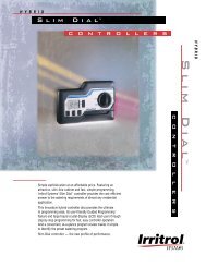
b. Underground installation using in-line AC valve (Fig. 4):<br />
Use DIG model DM075 valve assembly, which is a complete drip zone<br />
head assembly; includes 3/4" electric valve, #6, filter, #5, pressure<br />
regulator and #72, swivel adapter. Or build your own system using the<br />
same parts individually. This assembly can be connected via electric wire<br />
to any available station on your irrigation controller or to DIG model #8006,<br />
AC controller w<strong>it</strong>h an independent program for each valve.<br />
Note: Valve and head assembly should be installed into one standard rectangular valve box.<br />
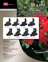
OPTION 3: BEGIN THE INSTALLATION BY RETROFITTING AN<br />
EXISTING 1/2" RISER (Fig. 6): Install a drip system on an<br />
e<br />
existing 1/2" riser by first unscrewing the sprinkler head from<br />
the riser and then screw #63, conversion elbow. Next attach a 6#<br />
1*<br />
#4, pressure regulator (hose thread) and finally the #18, 3/4"<br />
swivel adapter. Now connect e<strong>it</strong>her 1/2" polytube or Earthline<br />
1/2" Riser<br />
Brown PC dripline and secure the tubing or the dripline<br />
using #60, tubing holder stake. When combining drip irrigation<br />
Fig. 6<br />
w<strong>it</strong>h an existing sprinkler system, be sure to use high flow<br />
#34, 4 GPH drippers or #39, adjustable drippers w<strong>it</strong>h 0 to 20 GPH. After installing the drippers, open<br />
the valve and flush out the line. Then close off the end w<strong>it</strong>h a #71 end cap or #55, figure 8.<br />
If used w<strong>it</strong>h 1/4" microtube, after the pressure regulator, add a #21, adapter, connect the 1/4" microtube, and<br />
add #26, 1/4" tee as needed, and use w<strong>it</strong>h 4 GPH #34, drippers to a maximum flow rate of 35 GPH.<br />
Choosing Lateral Layout <strong>Installation</strong><br />
INSTALLATION METHOD USING POLYTUBE AS THE MAIN LATERAL: Install the 1/2" polytube above<br />
or below grade from the hose end, in-line controller, or in-line valve to the area to be watered. Use<br />
1/2" #19, tee, 1/2" #20, elbow where needed, and from the tee or elbow extend add<strong>it</strong>ional polytube<br />
to the plant area. Secure all 1/2" polytube to the ground using #60, holder stakes. Use 1/4"<br />
microtube as the feeder line and add drippers as needed.<br />
INSTALLATION METHOD USING A PVC PIPE AS THE MAIN LATERIAL: Install a 3/4" PVC pipe<br />
below grade from the controller or in-line valve to the area to be watered. Connect the PVC pipe to<br />
the in-line valve or to the battery operated controller. In each area to be watered add a 3/4" PVC tee<br />
(3/4" slip x 1/2" FNPT), and to the tee add a 6" or 8" 1/2" riser. To the riser add a #63 conversion<br />
elbow, and then a #18, swivel adapter or #22, swivel tee. Attach the 1/2" polytube or Earthline<br />
Brown PC <strong>Drip</strong>line, and secure all 1/2" polytube and dripline to the ground using #60, holder<br />
stakes. Add drippers or microsprinklers as needed to the 1/2" polytube or use the 1/4" microtube as the<br />
feeder line to the plants and add the drippers at the end of the microtube.<br />
g<br />
DM075 7001<br />
f<br />
g<br />
f<br />
9!<br />
Fig. 4<br />
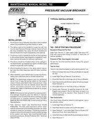
c. Above the ground installation using a battery operated<br />
controller w<strong>it</strong>h anti-siphon valve (Fig. 5): Use DIG model 2008-I and install<br />
<strong>it</strong> on a 10" to 12" 3/4" riser so <strong>it</strong> is at least 6" to 8" above the highest dripper<br />
or sprayer. Complete the head assembly by attaching a 3/4" #3, MNPT filter, a<br />
#5, pressure regulator to the downstream outlet. Finally attach a #16, 3/4"<br />
swivel adapter if using polytube, or 3/4" PVC female adapter if using PVC pipe.<br />
d. Above ground installation using a manual anti-siphon<br />
valve: Use any 3/4" manual anti-siphon valve and install <strong>it</strong> 8" to 12" above<br />
grade. Again the downstream will consist of the #3, filter, #5, pressure<br />
regulator, and the #72, swivel adapter if using polytube, or a 3/4" PVC female<br />
adapter if using PVC pipe. These valves can be easily converted to automatic<br />
operation by installing the DIG model #2006-I, battery operated controller.<br />
Note: Backflow device (#10) is not required on systems controlled by antisiphon<br />
valves.<br />
Fig. 5<br />
2008<br />
g<br />
f<br />
1^<br />
Fig. 4a<br />
7001<br />
g<br />
f<br />
6# 1*<br />
1/2" Riser<br />
3/4" x 1/2" x 3/4" PVC Tee<br />
2) 9@<br />
1/2" POLYTUBE AND 1/4" MICROTUBE INSTALLATION: Unroll the 1/2" polytube and lay <strong>it</strong> out in direct<br />
sunlight to warm <strong>it</strong> up and make <strong>it</strong> easier to work w<strong>it</strong>h. Use #60, stakes to secure the polytube to the ground.<br />
If the polytube is installed below grade, dig trenches 6" to 8" deep to keep the polytube a safe distance from<br />
cultivation practices. Leave the end of the polytube above the surface for periodic flushing.<br />
31 http://www.digcorp.com<br />
Questions – Call 1-800-344-2281<br />
32