Do-it-yourself! FREE Drip Irrigation Installation Guide - Garden Drip ...
Do-it-yourself! FREE Drip Irrigation Installation Guide - Garden Drip ...
Do-it-yourself! FREE Drip Irrigation Installation Guide - Garden Drip ...

Create successful ePaper yourself
Turn your PDF publications into a flip-book with our unique Google optimized e-Paper software.
<strong>FREE</strong> <strong>Drip</strong> <strong>Irrigation</strong><br />
<strong>Installation</strong> <strong>Guide</strong><br />
For many years, DIG Corporation has<br />
been providing homeowners,<br />
landscapers and growers w<strong>it</strong>h<br />
innovative, high qual<strong>it</strong>y low volume<br />
irrigation products.<br />
Whether your garden is large or small,<br />
you can depend on DIG for the<br />
a) answers<br />
b) right products, all the time<br />
c) finest in low volume irrigation<br />
We thank you very much for your<br />
business, and welcome your<br />
questions and comments.<br />
For questions about your DIG <strong>Drip</strong><br />
System Design, you can contact us at<br />
800-344-2281 or by email at<br />
dig@digcorp.com<br />
<strong>Do</strong>-<strong>it</strong>-<strong>yourself</strong>!<br />
Wise watering for<br />
beautiful landscape<br />
w<strong>it</strong>h DIG’s drip and<br />
microsprinkler<br />
products<br />
E PRINTED ON RECYCLED PAPER<br />
We at DIG strongly believe in conservation.<br />
Please recycle whenever you can.<br />
50% recycled 10% post-consumer.<br />
Version 83 040305<br />
DIG Corporation<br />
1210 Activ<strong>it</strong>y Drive • Vista, CA 92081<br />
http://www.digcorp.com<br />
© 2005 • Printed in USA • DS20-L<br />
www.digcorp.com
Introduction<br />
A<br />
Brief History: <strong>Drip</strong> irrigation has <strong>it</strong>s roots in agriculture.<br />
In many parts of the world <strong>it</strong> is one of the few options<br />
available for the irrigation of crops and vegetables in harsh<br />
climates w<strong>it</strong>h a lim<strong>it</strong>ed water supply. Its development<br />
depended on advancements in polyethylene tubing, and <strong>it</strong>s<br />
growth was most rapid in arid and drought-plagued regions.<br />
Beginning in the late 1960's farmers discovered that by using<br />
drip irrigation they could increase yields while lowering water<br />
use. The 80's saw drip irrigation making the trans<strong>it</strong>ion into<br />
commercial landscape and home gardens w<strong>it</strong>h mixed<br />
success. In today's market, drip irrigation is well trusted and<br />
used extensively in agriculture, commercial landscapes and residential gardens. <strong>Drip</strong> irrigation's<br />
popular<strong>it</strong>y is mainly because <strong>it</strong> provides a solution to many water conservation problems.<br />
<strong>Drip</strong> irrigation is the most efficient method of irrigation today. <strong>Drip</strong> irrigation (sometimes<br />
referred to as micro irrigation, low-flow irrigation, or trickle irrigation) is the slow and precise delivery<br />
of water directly to the plant roots. <strong>Drip</strong> irrigation is controlled e<strong>it</strong>her by hand or automatic timer.<br />
Because drip irrigation is applied at the root zone, <strong>it</strong> maintains an optimum moisture level in the soil<br />
at all times resulting in less water lost to evaporation and wind. The plant roots are consistently<br />
maintained in an ideal moisture level, combining the proper balance of water and air for better<br />
growth while minimizing weed germination and growth.<br />
Microsprinklers have many of the same benef<strong>it</strong>s as a drip system, such as low flow and low<br />
operating pressure. Unlike drip irrigation, microsprinklers/sprayers, distribute water over a wide area<br />
where low volume overhead irrigation is desired. Microsprinklers are used in areas where drip<br />
irrigation would not be practical such as large areas of groundcover, flowerbeds or oddly shaped<br />
areas. Like all low volume irrigation systems, they require a pressure regulator and filter, and are<br />
available in a variety of flow rates and diameters.<br />
Advantages and Benef<strong>it</strong>s<br />
WATER EFFICIENCY: <strong>Drip</strong> irrigation applies water only when and where <strong>it</strong> is needed, w<strong>it</strong>h less runoff<br />
and evaporation from leaves and soil. <strong>Drip</strong> irrigation systems can conserve great amounts of water<br />
when compared to sprinkler systems.<br />
EASE OF INSTALLATION: <strong>Installation</strong> is a very simple process, no special tools or glue are needed.<br />
REDUCED PEST PROBLEMS AND WEED GROWTH: Watering only the roots of plants w<strong>it</strong>h drip<br />
irrigation reduces the amount of water-borne pests and fungal diseases that spread by water<br />
movement. It also inhib<strong>it</strong>s germination of weeds in the area between plants.<br />
VERSATILITY: Low volume irrigation systems are designed for placement in both new and existing<br />
landscapes. They are also ideal for installation on difficult terrain such as on slopes, in oddly shaped<br />
areas, and s<strong>it</strong>es w<strong>it</strong>h high winds.<br />
ROOT ZONE: One of the most important aspects of installing a new drip irrigation system is that a<br />
totally new and more favorable root zone environment is created, which maintains a relatively<br />
constant soil moisture level. This creates stress free plants that actively grow and resist disease.<br />
ECONOMY: Investing in a low volume irrigation system can save you money by significantly lowering<br />
your garden water use, in turn lowering your water util<strong>it</strong>y bill.<br />
LONG LIFE: All DIG products are designed to w<strong>it</strong>hstand the harshest cond<strong>it</strong>ions in both home and<br />
commercial installations. They are manufactured from high qual<strong>it</strong>y, durable plastics and contain<br />
added quant<strong>it</strong>ies of the compound Carbon Black, making them resistant to the damaging effects of<br />
ultraviolet rays.<br />
http://www.digcorp.com<br />
From product information to planning, installation and maintenance, DIG provides all you need to<br />
know about drip irrigation. Follow our easy, step-by-step instructions to design and problem<br />
solve your drip system.<br />
Getting started ………………………………………………………………………………1<br />
Planning and designing your system …………………………………………………………1<br />
About the soil …………………………………………………………………………………2<br />
Determine soil types …………………………………………………………………………2<br />
Sketch your property or area ………………………………………………………………3-4<br />
Select the methods to start a system ………………………………………………………5-6<br />
Product classifications ………………………………………………………………………6-8<br />
Determine and calculate water flow requirements ……………………………………………8-9<br />
Watering schedules: drip and microsprinklers …………………………………………………9<br />
Helpful tips……………………………………………………………………………………9<br />
Spacing charts: drippers and microsprinklers (charts A through A1) ……………………………10<br />
Product descriptions: GPH, PSI, wetting diameter, patterns (chart B) ……………………………11<br />
<strong>Drip</strong> spacing, distance and head loss (charts C thru E) …………………………………………12<br />
Maximum length and spacing for microsprinklers (chart F) ……………………………………13<br />
Review the products ……………………………………………………………………13-26<br />
AC controller ……………………………………………………………………………13<br />
Battery operated controllers ………………………………………………………………13<br />
Hose end and in-line …………………………………………………………………14<br />
Anti-siphon ……………………………………………………………………………14<br />
Starter k<strong>it</strong>s: drip microsprinklers and drip tape …………………………………………14-16<br />
4-outlet, 6-outlet PC drippers and Maverick 12-outlet retrof<strong>it</strong> drip k<strong>it</strong>s ……………………16<br />
Head assembly: components of a drip zone ……………………………………………17-18<br />
Polytube and microtube ………………………………………………………………18-19<br />
1/2" and 1/4" f<strong>it</strong>tings ……………………………………………………………………19<br />
PC, button, flags and adjustable drippers ………………………………………………19-20<br />
Earthline Brown PC dripline ……………………………………………………………20<br />
<strong>Drip</strong> soaker tape, laser drilled soaker hose and accessories…………………………………21<br />
Microsprinklers, sprayers and foggers …………………………………………………21-24<br />
Retrof<strong>it</strong> heads and accessories…………………………………………………………24-25<br />
Accessories………………………………………………………………………………25-26<br />
Parts List ………………………………………………………………………………26-30<br />
<strong>Installation</strong> Instructions …………………………………………………………………30-42<br />
Head assembly ………………………………………………………………………30-31<br />
Lateral layout …………………………………………………………………………32-33<br />
<strong>Drip</strong> em<strong>it</strong>ter ………………………………………………………………………………34<br />
<strong>Installation</strong> example drawings …………………………………………………………35-36<br />
Earth Browth PC dripline ………………………………………………………………37<br />
Microsprayers / microsprinklers and foggers……………………………………………37-39<br />
Retrof<strong>it</strong> Products………………………………………………………………………40-41<br />
In<strong>it</strong>ial system start-up ………………………………………………………………………41<br />
Problems: potential causes and solutions …………………………………………………42-43<br />
Glossary ……………………………………………………………………………………43<br />
Maintenance ………………………………………………………………………………44<br />
Questions – Call 1-800-344-2281
Getting Started<br />
Compared to conventional sprinkler systems, drip irrigation systems are simple to design,<br />
inexpensive, and easy to install. In add<strong>it</strong>ion, drip irrigation can reduce disease problems<br />
associated w<strong>it</strong>h moisture on the leaves of plants. Trad<strong>it</strong>ional high volume, high pressure sprinkler<br />
systems require careful planning, extensive trenching, and special tools and glues. <strong>Drip</strong> irrigation<br />
systems can be easily installed above or below ground, w<strong>it</strong>hout special tools and glue or extensive<br />
technical knowledge. These efficient systems deliver water measured in Gallons Per Hour (GPH), and<br />
apply water only where <strong>it</strong> is needed. This can improve plant health, conserve water, and reduce the<br />
growth of weeds all at the same time.<br />
Design Layout Example<br />
Adjustable<br />
drippers or<br />
microsprinklers<br />
PC button<br />
drippers to shrubs<br />
<strong>Drip</strong>pers or misting<br />
sprayers for<br />
hanging plants<br />
Maverick 4- or<br />
6-outlets to<br />
retrof<strong>it</strong> 1/2" riser<br />
Planning and Designing Your System<br />
Microsprayers<br />
for flowerbeds<br />
Brown PC <strong>Drip</strong>line<br />
or drip soaker tape<br />
for a vegetable<br />
garden<br />
When designing an irrigation system we recommend considering the various areas and plants to<br />
be watered. We recommend using drip irrigation on trees, shrubs, vines, vegetables,<br />
flowerbeds, containers, pots, boxes, house foundations, on any individual plant, and narrow planting<br />
areas. Microsprinklers are best used on ground cover, flowerbeds, groups of plants, hillsides and on<br />
very sandy soil. In sandy soil water will percolate downward when using drip before <strong>it</strong> can spread far<br />
enough horizontally; microsprinklers will solve this problem because of the wide spray diameters.<br />
Avoid using microsprinklers in windy areas. High winds will disturb the microsprinkler spray pattern.<br />
CREATE A PLANT LIST (See plan graph on page 3)<br />
First, note and list the locations of your small and large trees, shrubs, groundcover, flowerbeds,<br />
containers and vegetable gardens. Then divide the plants into groups w<strong>it</strong>h similar watering needs,<br />
and plants that are in full sun or in a shaded area. Next, take into consideration the soil type, and<br />
concentration of plants. Use this information to select the water emission devices and to estimate<br />
the total flow rate (see view of design layout example).<br />
About the Soil<br />
Soil is like a storage room for plant nutrients. It is the<br />
medium through which water and nutrients move. It<br />
anchors plants and is a reservoir of water for plant growth.<br />
There are various types of soil w<strong>it</strong>h different characteristics<br />
which determine what types of dripper or microsprinkler<br />
should be used. In sandy soil, where water will tend to go<br />
straight down, use closely spaced 2 GPH drippers, 10" to 12" apart, or microsprinklers in a wider<br />
spacing. In loamy soil, the water will move slowly and will spread evenly, so use 1 GPH drippers w<strong>it</strong>h<br />
16" to 18" spacing. In clay soil, where water will be absorbed very slowly, use .5 GPH or 1 GPH<br />
drippers at a wider spacing (18" to 24" apart) or microsprinklers and sprayers w<strong>it</strong>h adequate spacing.<br />
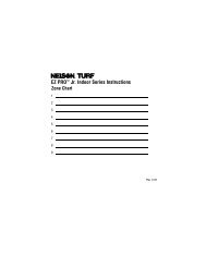
Determine Soil Types<br />
Sandy Loamy Dry<br />
W<strong>it</strong>h a drip system, water is applied slowly to the root zone at a single point. The water is acted<br />
upon by the forces of grav<strong>it</strong>y (downwards) and capillary action (outwards), producing a wetting<br />
pattern characteristic of the soil type and the water application rate. To determine which type of soil<br />
you have in a given area, take a handful of dry soil, grip tightly and release. Sandy (coarse) soil will<br />
crumble and fall apart, loam (medium) soil will hold together but then easily break apart, and clay<br />
will mold w<strong>it</strong>hout breaking. For more precise information, consider having a soil test conducted.<br />
Many univers<strong>it</strong>ies offer this service through their extension offices and master gardener programs.<br />
221 http://www.digcorp.com<br />
Questions – Call 1-800-344-2281<br />
22<br />
Questions – Call 1-800-344-2281<br />
2
Sketch Your Property or Area<br />
Start by making an accurate top view sketch of the areas that need to be watered (see Design<br />
Layout Example on page 2). Be sure to add details such as the outline of your home, any retaining<br />
walls, sidewalks, paved areas, all the plants, and the water source locations accurately and to scale.<br />
This will require measuring the area. We recommend using graph paper w<strong>it</strong>h small squares. This<br />
will make drawing to scale easier. Each small square on this manual graph could represent one<br />
foot of your property; this scale is usually appropriate for residential landscapes, or you can use<br />
1" graph = 10' of your area.<br />
3 http://www.digcorp.com<br />
Questions – Call 1-800-344-2281<br />
4
Select the Methods to Start a System<br />
Determining how to start a system, and what products to select are important decisions that<br />
should be made carefully. The correct choice will depend on the size of the area, the availabil<strong>it</strong>y<br />
of water outlets, the garden design/layout, and the type of plant material to be irrigated. Of the<br />
following five methods, choose the option(s) that is most feasible and appropriate for your particular<br />
use:<br />
1. Starting from a faucet, above ground installation using 1/2" polytube<br />
2. Above ground installation starting w<strong>it</strong>h an anti-siphon valve<br />
3. Below grade installation using an AC or DC in-line valve<br />
4. Retrof<strong>it</strong>ting an existing sprinkler system w<strong>it</strong>h multi-outlet drip heads<br />
5. Retrof<strong>it</strong>ting an existing riser w<strong>it</strong>h a conversion elbow<br />
The typical home garden may require one or more watering zones. For each s<strong>it</strong>uation, DIG provides a<br />
convenient and efficient irrigation solution.<br />
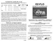
METHOD 1: Above ground layout starting from a faucet using only the 1/2" black polytube as the<br />
main lateral. This is the simplest way to install a drip system. It can be easily automated by adding<br />
DIG's model 7001 or 9001D controller.<br />
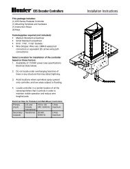
METHOD 3: Below grade layout starting from an in-line valve or in-line battery operated controller<br />
using buried 3/4" PVC pipe as the main lateral line, and 1/2" dripline as the sublateral.<br />
18" Valve Box<br />
DM075 Valve Assembly<br />
3/4" PVC Pipe<br />
3/4" Female Adapter<br />
/ ___<br />
g<br />
18" Valve Box<br />
7001 Battery Op. Controller 3/4" Female Adapter<br />
/ ___<br />
/ ___ f<br />
/ ___<br />
3/4" PVC Pipe<br />
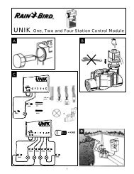
METHOD 4: Retrof<strong>it</strong> a sprinkler system or retrof<strong>it</strong> a 1/2" riser by removing the sprinkler heads and<br />
attaching a single, 4-, 6-, or 12-outlet drip head. From the drip head, extend microtube to the plants<br />
and secure w<strong>it</strong>h a #57 or #67 stake, if needed.<br />
12 Outlets 4 Outlets 6 Adjustable Outlets 6 Outlets Single Outlet<br />
g<br />
f<br />
3/4" ___<br />
Riser \<br />
3/4" ___<br />
Slip Tee \<br />
/ ___ 9001D Timer<br />
#10 Backflow Device<br />
/ ___<br />
/ ___ #10 Backflow Device<br />
/ ___<br />
#13 FHT Filter<br />
3/4" ___<br />
/ ___ #13 FHT Filter<br />
Riser \<br />
#4 FHT Pressure<br />
/ ___ Regulator<br />
3/4" ___ #4 FHT Pressure<br />
#18 FHT<br />
/ __<br />
/ ___ Slip Tee \<br />
Regulator<br />
Swivel Adapter<br />
/ __ #18 FHT<br />
Swivel Adapter<br />
/ _______ 3/4" PVC Pipe<br />
/ _______ 3/4" PVC Pipe<br />
Maverick<br />
8& 8^ 8( 8%<br />
METHOD 5: Retrof<strong>it</strong> a 1/2" riser using conversion elbow, pressure regulator and swivel adapter. Use<br />
the polytube above or below the ground as the main laterals.<br />
METHOD 2: Above the ground layout starting from an anti-siphon valve and using a 3/4" PVC pipe or<br />
1/2" polytube as the main lateral. All anti-siphon valves must be installed at least 6" above the<br />
highest head.<br />
*Remove cover and screen prior to installation.<br />
6#<br />
__<br />
\<br />
/ ___<br />
1*<br />
1/2" riser<br />
Battery operated controller<br />
w<strong>it</strong>h<br />
3/4" Anti-siphon valve<br />
___<br />
\<br />
Battery operated controller<br />
w<strong>it</strong>h<br />
Product Classifications and Watering Method<br />
#6 – 3/4" 155 mesh filter*<br />
#5 – 3/4" FNPT 25 PSI<br />
pressure regulator<br />
___<br />
\<br />
___<br />
\<br />
#16 – 3/4" FNPT swivel adapter<br />
#19 – 1/2" elbow<br />
___<br />
\<br />
___<br />
\<br />
1/2" polytube<br />
3/4" Anti-siphon valve<br />
3/4" 12" MNPT riser<br />
#6 – 3/4" 155 mesh filter*<br />
#5 – 3/4" FNPT 25 PSI<br />
pressure regulator<br />
PVC 3/4" x 3/4" x 3/4" tee<br />
PVC 3/4" elbow<br />
PVC 3/4" PVC pipe<br />
___<br />
\<br />
_<br />
\<br />
___<br />
\<br />
____<br />
\<br />
___\<br />
(continued through page 8)<br />
Most residential landscapes are qu<strong>it</strong>e diverse and usually consist of up to four basic plant groups:<br />
1. Individual foundation trees and shrubs<br />
2. Densely planted flowerbeds, perennial beds and/or groundcover areas<br />
3. Container plants, hanging baskets, window boxes<br />
4. Vegetable gardens and row crops<br />
5 http://www.digcorp.com<br />
Questions – Call 1-800-344-2281<br />
6
DIG provides different emission devices specifically designed to effectively and efficiently irrigate<br />
each plant group. To choose the correct emission device, please refer to the following guidelines:<br />
CATEGORY 1—Trees and Shrubs: Pressure Compensating (PC), button, adjustable and flag<br />
drippers are su<strong>it</strong>ed for virtually any layout w<strong>it</strong>h plants such as shrubs, trees, vines, roses. They are<br />
most efficient when plants are spaced few feet apart (See chart A1, B, and F on pages 10-13 for<br />
recommended number of drippers, dripper spacing per plant or area and maximum length to run the<br />
1/2" polytube and 1/4" microtube). Model G77 is an excellent starter k<strong>it</strong> for this type of installation.<br />
/ ___ / ___<br />
3(<br />
/ ___ 1/4" microtube<br />
/ ___<br />
3) 3$ 3*<br />
3! 3@ 3&<br />
\___<br />
1/2" polytube<br />
\___<br />
6)<br />
CATEGORY 3—Container Plants, Hanging Baskets, and Window Boxes: For containers, potted<br />
plants, and hanging baskets, use #46 pot and basket misters or #37 – .5 GPH button dripper. The<br />
#46 mister is most appropriate for hanging plants and plants that benef<strong>it</strong> from moist foliage. Potting<br />
soils are very porous and misters prevent drainage problems by dispersing the water over a larger<br />
area of the soil surface. The #46 pot and basket mister is an ideal choice for all sizes and shapes of<br />
containers. Larger containers may require more than one mister. (See chart A, A1, B, C, and C1 on<br />
pages 10 and 12 for recommended spacing, flow rates, wetting diameter and pattern). Model MD50<br />
is an excellent starter k<strong>it</strong> for this type of installation.<br />
3&<br />
2% 6% 4^<br />
CATEGORY 4—Vegetable <strong>Garden</strong>s and Row Crops: Earthline Brown PC dripline, drip soaker<br />
tape, and 1/4" laser drilled soaker line are ideal for vegetable gardens, row crops, seed beds,<br />
planters, and narrow planting areas (See chart D on page 12 for maximum length to run). These<br />
products will saturate the soil under the entire length of the dripline or drip tape. An excellent starter<br />
k<strong>it</strong> is the ST100 or Earthline Brown PC dripline w<strong>it</strong>h a 1 GPH dripper every 18".<br />
CATEGORY 2—Flowerbeds and Groundcover: Microsprinklers and microsprayers are best su<strong>it</strong>ed<br />
for densely planted flowerbeds, annuals, groundcovers, groups or clusters of plants, small slopes,<br />
and on s<strong>it</strong>es w<strong>it</strong>h very sandy soil. In sandy soil water will percolate downward before <strong>it</strong> can spread<br />
far enough horizontally (see charts A1, B and F, on pages 10-13 for recommended spacing, flow<br />
rates, diameter, pattern, and maximum length to run 1/2" polytube). Avoid microsprinklers in areas<br />
where <strong>it</strong> is windy; high winds will disturb the microsprinkler spray pattern. Model EF55 and GE200<br />
are excellent for this type of installation.<br />
40’ 40'<br />
14’<br />
14'<br />
26’<br />
26'<br />
28’<br />
28'<br />
42 32 GPH GPH<br />
24<br />
24<br />
GPH<br />
GPH<br />
21<br />
21<br />
GPH<br />
GPH<br />
40<br />
40<br />
GPH<br />
GPH<br />
8'R 8’ up up to to 20' 10’ 7'R 7’ 14’ 13'<br />
.8 1’<br />
14 14 GPH GPH 0-30 GPH<br />
14 14 GPH GPH 10 10 GPH GPH<br />
2 GPH<br />
7 http://www.digcorp.com<br />
9& 9% 4) 4%<br />
4* 9@ 4( 4! 4^<br />
Determine and Calculate Water Flow Requirements<br />
To determine the total flow w<strong>it</strong>hin a drip system section or zone, add up the total number of<br />
drippers and their flow rates. The same method should be used for microsprinklers and<br />
microsprayers.<br />
Example: You have designed a system using 40 drippers, consisting of 20 – 1 GPH and 20 – 2 GPH<br />
drippers, plus 2 microsprinklers at 14 GPH each.<br />
Calculate total flow rates:<br />
20 – 1 GPH drippers = 20 gallons per hour<br />
20 – 2 GPH drippers = 40 gallons per hour<br />
2 – 14 GPH microsprinklers = 28 gallons per hour<br />
Total flow rate = 88 Gallons Per Hour (GPH), or (dividing by 60) = 1.46 Gallons Per Minute (GPM)<br />
TIP: The maximum recommended flow rate for a single line of 1/2"<br />
polytube is 220 GPH (3.6 GPM). If you exceed the recommended flow<br />
rate, add another line of 1/2" polytube to your zone or section.<br />
If the flow rate from a single valve or a zone using a 3/4" pipe exceeds 9 GMP (540 GPH), another<br />
valve or zone should be added. This can be done by dividing the area to be irrigated in half and build<br />
a valve manifold for each new zone. Another option is to consider using a valve or a zone for each<br />
type of application. For example, one valve can be used w<strong>it</strong>h your drip layout and one valve w<strong>it</strong>h a<br />
microsprinkler layout.<br />
TIP: The recommended flow rate for any section or a zone using 3/4"<br />
valve is 540 GPH or 9 GPM. If using w<strong>it</strong>h a Model 9001 controller the<br />
maximum flow rate is 312 GPH or 5.2 GPM.<br />
Questions – Call 1-800-344-2281<br />
8
If in doubt about the capac<strong>it</strong>y of your water source, make sure that no water is being used in the<br />
house, and then time how long <strong>it</strong> takes to fill a measured bucket from one of the outside faucets. For<br />
example: turn on the faucet slowly until <strong>it</strong> is fully open and measure water capac<strong>it</strong>y. If <strong>it</strong> takes 20<br />
seconds to fill a 3 gallon bucket, then the maximum flow rate available per hour is 3 gallons x 3<br />
times a minute = 9 Gallons Per 1 Minute (GPM) x 60 minutes = 540 Gallons per Hour (GPH); 540<br />
divided by 60 = 9 GPM, so you have 9 GPH available from your single water source. Should the<br />
system require higher flow rates, divide the system in two by adding another valve.<br />
PLANNING FOR THE FUTURE: In any design that you create, make sure to plan for the future. When<br />
plants mature, they may require more water. Watering times can be lengthened to meet those needs,<br />
but generally, more drippers should be added to supply the maturing plant. Also, new plants may be<br />
added to the landscape, so leave some room in the overall design by having about 20%-30% more<br />
water capac<strong>it</strong>y available. 3/4" faucets and 3/4" anti-siphon valves will almost always provide more<br />
than enough water for most home landscapes and garden s<strong>it</strong>es.<br />
DRIPPER WATERING SCHEDULE<br />
WATERING FREQUENCY<br />
TYPE OF PLANT LENGTH OF WATERING HOT WARM COOL<br />
Flowers, vegetables 30 min – 1 hr 1-2 days 3 days 3-4 days<br />
Small trees, shrubs 1-2 hours 1-2 days 2-3 days 3-4 days<br />
Vines 3-6 hours 1-2 days 2-3 days 3-4 days<br />
Medium trees, shrubs 5-7 hours 2-3 days 2-3 days 4-5 days<br />
Large trees, shrubs 6-8 hours 1-2 days 2-3 days 5-6 days<br />
Pots to 15" 3-5 minutes 1-2 days 2-3 days 4-5 days<br />
Pots over 15" 5-10 minutes 1-2 days 2-3 days 4-5 days<br />
MICROSPRINKLER WATERING SCHEDULE<br />
Flowerbeds, groundcover 30 min – 1 hr 1-2 days 3 days 4-6 days<br />
Small trees 1-2 hours 2-3 days 4-5 days 5-6 days<br />
Medium trees 2-3 hours 2-3 days 4-5 days 6-7 days<br />
Large Trees 2-5 hours 2-3 days 4-5 days 5-7 days<br />
Greenhouses, hothouses 5-10 minutes 2-4 times/day 2 times/2 days 1 time/2 days<br />
Helpful Tips<br />
If this is the first time you are installing a drip or microsprinkler system, we recommend trying<br />
one of our starter k<strong>it</strong>s. Each k<strong>it</strong> contains everything you need to install a basic system, w<strong>it</strong>h<br />
the exception of a pressure regulator which may be required if your pressure is over 25 PSI. All<br />
of the parts are available separately to add on later.<br />
Minimum working pressure (PSI) for a drip or microsprinkler system is 15 PSI, maximum<br />
working pressure is 25 PSI. If your system's pressure is higher than this, install a pressure<br />
regulator (#4, #5, #8) after the filter.<br />
If you are using pressure compensating drippers, you can achieve runs longer than 400'.<br />
Please refer to chart C1 on page 25 to see just how far you can go.<br />
You should not exceed 220 GPH on a single 1/2" line, 35 GPH on a single 1/4" line, or 5<br />
GPH on a single 1/8" line.<br />
✔<br />
✔<br />
✔<br />
✔<br />
✔<br />
✔<br />
Allowing the 1/2" polytube to s<strong>it</strong> in the sun will warm and soften the plastic, making <strong>it</strong><br />
easier to work w<strong>it</strong>h.<br />
If you are having difficulty inserting your 1/4" barbs into 1/4" microtube, dipping the<br />
microtube into warm water will make <strong>it</strong> more pliable.<br />
Water in the early morning hours for the best results.<br />
CHART A AND CHART A1: Determine the number of drippers, microsprinklers and the flow rates<br />
recommended.<br />
Chart A: Spacing Chart <strong>Drip</strong>pers<br />
RECOMMENDED NUMBER OF DRIPPERS PER PLANT<br />
Type of plants<br />
Number of drippers and spacing<br />
Flowers<br />
One dripper (.5 GPH) in clay soil, spaced every 18"- 24". One<br />
dripper (1 GPH) in loamy & sandy soil spaced every 12" to 18".<br />
Vegetables<br />
One dripper (.5 GPH) in clay soil, spaced every 18". One dripper<br />
(1 GPH) in loamy & sandy soil spaced every 12" to 18", Earthline<br />
Brown PC dripline or soaker tape.<br />
Small shrubs and roses One dripper (1 GPH) per plant in clay soil. One to two (1 GPH)<br />
(up to 2' high) drippers in loamy & sandy soil, spaced every 12" to 18".<br />
Medium shrubs and small trees Two drippers (1 GPH) per plant in clay soil spaced 10" from center.<br />
(2' to 4' high)<br />
Two drippers (2 GPH) spaced 9"-12" from center or 3 (1 GPH)<br />
drippers in loamy & sandy soil, spaced 12" to 18" apart.<br />
Medium shrubs and small trees Six drippers (.5 GPH) in clay soil spaced 18"-24" apart in a loop.<br />
(4' to 6' high)<br />
Two to three drippers (2 GPH) in loamy soil spaced 16"-18" apart<br />
in a loop or 4 (1 GPH) drippers in sandy soil, spaced 12" to 18"<br />
apart in a loop around the tree.<br />
Chart A1: Spacing Chart Microsprinklers<br />
RECOMMENDED NUMBER OF DRIPPERS OR MICROSPRINKLERS PER PLANT<br />
Number of drippers, microsprinklers and spacing<br />
Large trees (6' and up ) Five drippers (2 GPH ) per plant in clay soil spaced 18" to 24" apart<br />
around the tree. Five drippers (2 GPH) in loamy & sandy soil,<br />
spaced 12" to 18" apart around the tree or one minisprinkler<br />
model 8809-1B (#94) near the base.<br />
Groundcover<br />
Select microsprinklers or microsprayers depending on the area you<br />
wish to cover (see chart B and E on pages 11 and 12 for diameter<br />
and distance). For narrow areas up to 2' wide, space drippers<br />
(1 GPH) in clay soil 18" to 24" apart or use Earthline Brown PC<br />
dripline. In loamy & sandy soil, space drippers (2 GPH) 12" to 24"<br />
apart.<br />
Greenhouses Use minisprinkler #95 spaced every 5'-6', microsprinkler #40<br />
(germination & propagation) every 10' to 12' or #43 every 3' to 5'. Also, mister #43 can be used<br />
every 3', and placed 8" above the plants in a rectangular pattern.<br />
Greenhouses and nurseries Use mister #43, or fogger #98 or #99 spaced 3' to 5' apart,<br />
(cooling)<br />
6' to 8' feet above the ground.<br />
Hanging baskets and boxes One dripper (.5 GPH) for up to 7 gallon plants. One sprayer #46<br />
(1 gallon to 25 gallons) installed upside down or mounted on a spike for 5 to 25 gallon<br />
sized plants.<br />
TIP: We recommend spacing drippers no closer than 12" apart.<br />
9 http://www.digcorp.com<br />
Questions – Call 1-800-344-2281<br />
10
CHART B: Product Descriptions: GPH, PSI, Wetting Diameter, Patterns<br />
Should you choose to use foggers, microsprinklers or misters, CHART B illustrates the various<br />
coverages and flow rate available for each model.<br />
Locator Flow Working Description Diam. Pattern/<br />
# Rates Pressure (ft.) degrees<br />
(GPH) (PSI)<br />
40 16-21 25 Microsprinkler w<strong>it</strong>h heads for different patterns, 26 360/180<br />
on spike assembly<br />
/90/strip<br />
41 7-10 25 Jet sprayer on 10/32 threaded barb 5 90/180/<br />
360<br />
41 7-10 25 Jet sprayer preassembled on spike assembly 13 360<br />
42 12-14 25 Jet sprayer w<strong>it</strong>h microtube and barb 18 strip<br />
43 6-7 25 Fogger/mister on 10/32 threaded barb 5 360<br />
44 11-14 25 Microsprinkler preassembled on spike assembly 25 360<br />
or 10/32 thread<br />
45 39-40 25 Mini-compact microsprinkler on spike assembly 28 360<br />
46 1.2 - 2 25 Sprayer on barb w<strong>it</strong>h mini stake .8 360<br />
47 12-14 25 Jet sprayer w<strong>it</strong>h 10/32 thread or on spike assembly 12 360<br />
48 12-14 25 Jet sprayer w<strong>it</strong>h 10/32 thread or on spike assembly 8R 180<br />
49 12-14 25 Jet sprayer w<strong>it</strong>h 10/32 thread or on spike assembly 7R 90<br />
47 12-14 25 Jet sprayer on 12" pop-up 12 360<br />
48 12-14 25 Jet sprayer on 12" pop-up 8R 180<br />
49 12-14 25 Jet sprayer on 12" pop-up 7R 90<br />
91 0-30 25 Adjustable flow jet sprayer on spike assembly 25 360<br />
92 0-30 25 Adjustable flow jet sprayer on spike assembly 10R 180<br />
93 0-30 25 Adjustable flow jet sprayer on spike assembly 9R 90<br />
94 8-10 25 Minisprinkler preassembled on spike assembly 10 360<br />
95 22-24 25 Minisprinkler preassembled on spike assembly 14 360<br />
96 29-32 35 Adjustable one jet stream microsprinkler on spike assembly 42 30-330<br />
97 29-32 25-35 One jet stream microsprinkler preassembled on spike assembly 40 360<br />
98 .8 40-80 Fine droplet fogger for cooling on 10/32 thread 1-2 360<br />
99 .8 40-80 Fine droplet fogger for cooling on 1/4" barb 1-2 360<br />
100 7 25 Flow regulated microsprinkler assembly 15 360<br />
101 0-20 25 Adjustable sprayer on a spike 1-12 360<br />
11 http://www.digcorp.com<br />
One of the advantages of using a drip system and microsprinklers is the area that can be<br />
covered. Because these devices require low water flow, they allow you to cover a large area<br />
using a single 1/2" polytube. CHARTS C, C1, D, E AND F will assist you in determining how far you<br />
can run your polytube, and how many drippers or microsprinklers can be used depending on the<br />
spacing and flow rates.<br />
CHART C: MAXIMUM RUN OF 1/4" MICROTUBE OR 1/2" DRIPTUBING WITH PC DRIPPERS<br />
<strong>Drip</strong>per Flow Rate <strong>Drip</strong>per spacing in feet <strong>Drip</strong>per spacing in feet<br />
on 1/4" microtube<br />
on 1/2" polytube<br />
<strong>Drip</strong>per Locator # Flow 1' 2' 3' 4' 5' 1' 2' 3' 4' 5'<br />
PC 30/81 1 GPH 35 50 72 88 105 320 530 670 820 970<br />
PC 38 2 GPH 25 36 45 56 65 190 310 420 510 610<br />
PC 34 4 GPH 14 22 30 36 40 120 200 250 320 450<br />
CHART C1: MAXIMUM LENGTH RUN OF 1/4" MICROTUBE AND 1/2" DRIPTUBING WITH BUTTON<br />
AND FLAG DRIPPERS<br />
<strong>Drip</strong>per Flow Rate <strong>Drip</strong>per spacing in feet <strong>Drip</strong>per spacing in feet<br />
on 1/4" microtube<br />
on 1/2" polytube<br />
<strong>Drip</strong>per Locator # Flow 1' 2' 3' 4' 5' 1' 2' 3' 4' 5'<br />
Button 31 1 GPH 17 26 36 24 45 140 230 310 350 400<br />
Button 37 .5 GPH 26 40 50 64 70 195 320 430 525 610<br />
Button 32 2 GPH 10 16 21 24 30 80 145 175 230 270<br />
Flag 35 1 GPH 17 26 36 40 45 125 220 300 330 370<br />
Adjustable 39 1 to 10 GPH Depends on flow rates<br />
CHART D: DISTANCE YOU CAN RUN 1/2" DRIP SOAKER TAPE LINE, 1/4" LASER DRILLED<br />
SOAKER HOSE AND EARTHLINE BROWN PC DRIPLINE<br />
Model # Description Flow rates (GPH) Spacing 25 PSI 45 PSI<br />
ST100/500 <strong>Drip</strong> soaker tape line .6 12" 280' N/R<br />
SH50 1/4" Laser drilled soaker hose .5 12" 30' N/R<br />
B18100 1/2" Earthline Brown PC dripline 1 18" 330'<br />
CHART E: HEAD LOSS FOR 1/2" AND 1/4" POLYTUBE<br />
Polyethylene (PE) tubing head loss<br />
Distribution tubing head loss<br />
1/2" (.600 ID x .700 OD) 1/8" Vinyl 1/4" Vinyl<br />
Vel. P.S.I Vel. P.S.I. Vel. P.S.I.<br />
GPM F.P.S. Loss GPM GPH F.P.S. Loss F.P.S. Loss<br />
0.25 0.28 0.04 0.05 3.0 1.3 4.77 0.8 1.62<br />
0.50 0.57 0.16 0.10 6.0 2.6 17.20 1.6 5.86<br />
0.75 0.85 0.34 0.15 9.0 3.9 36.45 2.5 12.40<br />
1.00 1.13 0.58 0.20 12.0 5.2 62.06 3.3 21.12<br />
1.25 1.42 0.88 0.25 15.0 6.5 93.77 4.1 31.91<br />
1.50<br />
1.75<br />
1.70<br />
1.98<br />
1.23<br />
1.64<br />
shaded area is not recommended<br />
2.00 2.27 2.10<br />
2.25 2.55 2.61<br />
2.50 2.83 3.17<br />
2.75 3.22 3.78<br />
3.00 3.40 4.44<br />
3.25 3.68 5.15<br />
Questions – Call 1-800-344-2281<br />
12
CHART F: MAXIMUM LENGTH AND SPACING WITH MICROSPRINKLERS, SPRAYERS OR<br />
FOGGERS ON 1/2" POLYTUBE<br />
Flow Deviation 7%<br />
Microsprinkler, sprayer and mister spacing in feet<br />
Product Locator. # Nominal 3' 6' 9' 12' 15' 18' 20'<br />
Flow Rates<br />
Microsprinkler 40 21 GPH N/R N/R N/R 104 131 145 161<br />
Microsprinkler 40 21 GPH N/R N/R N/R 104 131 145 161<br />
Ray jet sprayer 41 10 GPH N/R 177 207 260 320 367 402<br />
Jet sprayer 42 14 GPH N/R NR 114 141 162 191 202<br />
Mister 43 7 GPH N/R 135 175 201 237 249 263<br />
Microsprinkler 44 14 GPH N/R N/R 114 141 162 191 202<br />
Insect proof microsprinkler 45 40 GPH N/R N/R N/R N/R 73 103 113<br />
Pot and basket mister 46 2 GPH 167 230 304 N/R N/R N/R N/R<br />
Spray jet 47/48/49 14 GPH N/R 87 114 141 162 191 202<br />
Spray jet on spike 47/48/49 14 GPH N/R 87 114 141 162 191 202<br />
Spray jet 12" pop-up 47/48/49 14 GPH N/R 87 114 141 162 191 202<br />
Minisprinkler 94 10 GPH N/R 136 207 252 315 360 399<br />
Minisprinkler 95 24 GPH N/R N/R 86 113 138 168 190<br />
Compact microsprinkler 96/97 32 GPH N/R N/R N/R N/R N/R 128 138<br />
Flow regulated microsprinkler 100 7 GPH N/R<br />
NR: Not Recommended<br />
Review of Our Products<br />
provides an extensive line of microirrigation products and accessories from controllers,<br />
DIGstarter k<strong>it</strong>s, drip em<strong>it</strong>ters, dripline, microsprinklers, foggers, tubing, f<strong>it</strong>tings, and<br />
accessories to complete new and existing systems.<br />
AC Controllers<br />
Acontroller should be selected w<strong>it</strong>h care. This is especially true if the<br />
irrigation system is watering a combined drip and sprinkler system w<strong>it</strong>h<br />
different settings for each valve or zone. DIG models 8004 four station and<br />
8006 six station controllers are very simple to program. Both allow for each<br />
valve in the system to be programmed independently, from 1 minute to 12<br />
hours in one minute increments. They both have four start times for each<br />
valve allowing for mixed irrigation applications for drip and sprinkler systems.<br />
Battery Operated Controllers<br />
13 http://www.digcorp.com<br />
8006<br />
Battery operated controllers and timers are ideal for any watering system that needs a solution<br />
for automation w<strong>it</strong>hout connecting wire to an AC source. These controllers have a wide range of<br />
features and use one 9-volt battery, w<strong>it</strong>h a battery life of up to two years.<br />
Battery Operated Controllers: Hose End and In-line<br />
Our hose end battery operated controllers are available w<strong>it</strong>h e<strong>it</strong>her hose or pipe thread, low flow<br />
or high flow, w<strong>it</strong>h LCD display or w<strong>it</strong>hout, and are covered by a 3-year lim<strong>it</strong>ed warranty.<br />
IN-LINE CONTROLLER<br />
• MODEL 7001: High flow w<strong>it</strong>h up to 28 GPM or 1680 GPH, has hose and pipe threads and LCD display.<br />
HOSE END TIMER<br />
• MODEL 9001 OR 9001DB: Low flow w<strong>it</strong>h up to 5.2 GPM or 312 GPH, has hose thread only, and<br />
LCD display for programming. (If you install a system using this controller, make sure not to exceed<br />
the recommended flow rate).<br />
• MODEL 9001EZ: Low flow w<strong>it</strong>h up to 5.2 GPM or 312 GPH, has hose thread only and uses two<br />
dials and one button for programming. (If you install a system using this controller, make sure not to<br />
exceed the recommended flow rate).<br />
7001D 9001D 9001DB 9001EZ<br />
Battery Operated Controllers: Anti-siphon<br />
Our anti-siphon battery operated controllers are used for above ground installation and are<br />
available w<strong>it</strong>h e<strong>it</strong>her a 3/4" anti-siphon valve or w<strong>it</strong>h a retrof<strong>it</strong> actuator to convert most 3/4" or<br />
1" manual anti-siphon valves on the market to automatic operation.<br />
MODEL 2008-I: 3/4" anti-siphon valve and controller w<strong>it</strong>h LCD display. Maximum flow rate: 10 GPM.<br />
MODEL 2006-I: Converts manual anti-siphon<br />
valves to automatic operation; includes controller<br />
w<strong>it</strong>h LCD display, actuator and all the parts needed<br />
to connect to an existing 3/4" or 1" manual antisiphon<br />
valve.<br />
Starter K<strong>it</strong>s<br />
2008-I<br />
provides a variety of starter k<strong>it</strong>s to help start a drip, microsrinkler, or retrof<strong>it</strong> system. DIG<br />
DIG k<strong>it</strong>s are the perfect way to familiarize <strong>yourself</strong> w<strong>it</strong>h the advantages and benef<strong>it</strong>s of low<br />
volume irrigation. Our k<strong>it</strong>s utilize many different products from our line to provide you a starting<br />
point. They are all in one package.<br />
Microsprinkler, Microsprayer, <strong>Drip</strong> and<br />
<strong>Drip</strong> Soaker Tape K<strong>it</strong>s<br />
2006-I<br />
MODEL EF55 AND EF55AS (WITH BACKFLOW DEVICE) MICROSPRINKLER WATERING KITS: The<br />
microsprinkler k<strong>it</strong> can be used for watering groundcovers and flowerbeds. This k<strong>it</strong> can water up to<br />
250 sq. ft. w<strong>it</strong>h the option to expand. It contains five large-diameter #40 microsprinklers on spikes,<br />
each w<strong>it</strong>h 21 GPH, and each watering a full circle up to 26' in diameter. It also includes inserts for<br />
Questions – Call 1-800-344-2281<br />
14
watering up to a 6' diameter in partial circles of 90° and<br />
180°, and in a strip pattern of up to 12'. In add<strong>it</strong>ion, <strong>it</strong> has<br />
two small-diameter sprayers w<strong>it</strong>h 10 GPH #41 each on<br />
10/32 thread. These sprayers also water a full 360° and<br />
include tips for 90° and 180° which can be inserted directly<br />
into the 1/2" polytube. The k<strong>it</strong> includes 50' of 1/2" polytube,<br />
swivel adapters, a tee, a coupling, a punch, hose ends and<br />
plugs. (If pressure in your system exceeds 30 PSI, add a #4,<br />
pressure regulator.)<br />
MODEL FM01 AND FM01AS (WITH BACKFLOW DEVICE)<br />
PATIO WATERING KIT: This mini drip k<strong>it</strong> is designed for<br />
watering container plants, pots, and planter boxes, indoors<br />
or outdoors. The k<strong>it</strong> can cover up to 10 plants and has the<br />
option to expand up to 35 plants using 1 GPH drippers. It<br />
contains ten #30, 1 GPH PC drippers. The k<strong>it</strong> also includes<br />
60' of 1/4" microtube, adapters, tees, barbs, stakes,<br />
mounting clips, and 1/4" valves. (If pressure in your system<br />
exceeds 30 PSI, add a #4, pressure regulator.)<br />
MODEL G77 AND G77AS (WITH BACKFLOW DEVICE) DRIP<br />
WATERING KIT: This drip k<strong>it</strong> is designed to water landscape<br />
areas w<strong>it</strong>h shrubs, trees, vines, and flowerbeds. It can cover<br />
up to 150 sq. ft. using our 1 and 4 GPH PC drippers w<strong>it</strong>h<br />
option to expand. It contains twenty #30, 1 GPH and two<br />
#34, 4 GPH PC drippers. The k<strong>it</strong> also contains 50' of 1/2"<br />
polytube, 50' of 1/4" microtube, swivel adapters, 1/2" and<br />
1/4" tees, coupling, barbs, 1/2" and 1/4" stakes, hose ends,<br />
punch, 1/4" shut off valve, and plugs. (If pressure in your<br />
system exceeds 30 PSI, add a #4, pressure regulator.)<br />
MODEL GE200 DRIP AND MICROSPRAYER KIT: This drip<br />
and microsprayer k<strong>it</strong> is a complete system that can be used<br />
for watering groundcovers, flowerbeds, trees, vines, and<br />
shrubs. This k<strong>it</strong> can water up to 700 sq. ft. w<strong>it</strong>h the option to<br />
expand. It contains four #47, 90° microsprayers w<strong>it</strong>h 14<br />
GPH each, four #48, 180° microsprayers w<strong>it</strong>h 14 GPH each,<br />
three #49, 360° microsprayers w<strong>it</strong>h 14 GPH each, and<br />
twenty #30, 1 GPH PC drippers. The k<strong>it</strong> also includes 200' of<br />
1/2" polytube, 50' 1/4" microtube, eleven 13" clip stakes<br />
w<strong>it</strong>h 24" microtube and barb, backflow device, pressure<br />
regulator, swivel adapters, 1/2" and 1/4" tees, elbows,<br />
coupling, punch, barbs, 1/2" and 1/4" stakes, hose end, and plugs.<br />
MODEL MD50 MIST AND DRIP RETROFIT WATERING<br />
KITS: This drip and mist k<strong>it</strong> is designed to retrof<strong>it</strong> a 1/2"<br />
riser sprinklers to water large planters, containers, and<br />
boxes. The k<strong>it</strong> can cover up to six planters or boxes. It<br />
contains four #39, 0-20 GPH adjustable drippers on spikes<br />
and two #46, 2 GPH foggers. The k<strong>it</strong> also contains 50' of<br />
1/4" microtube, 1/2" adapter w<strong>it</strong>h 1/4" barb outlet,<br />
1/4" tees, stakes, and plugs.<br />
EF55<br />
FM01<br />
G77<br />
GE200<br />
MD50<br />
MODEL ST100 AND AT100AS (WITH BACKFLOW DEVICE) DRIP &<br />
ST100<br />
SOAKER VEGETABLE WATERING KIT: This k<strong>it</strong> is the perfect way to<br />
water a vegetable garden! This k<strong>it</strong> can cover up to five beds, each 20'<br />
long, using our drip soaker tape. The k<strong>it</strong> contains 100' of drip soaker<br />
tape w<strong>it</strong>h .8 GPH drippers sonically welded inside the tape every 12".<br />
The k<strong>it</strong> also contains 5' 1/2" polytube, swivel adapters, drip tape<br />
coupling, drip tape ends, drip tape reducers, hose ends, drip tape to<br />
drip hose connector, punch, plugs, installation instructions and a<br />
booklet on how to plan and prepare a vegetable garden. (If pressure in<br />
your system exceeds 30 PSI, add a #4, pressure regulator.)<br />
MODEL R750 ADJUSTABLE MICROSPRAYER KIT: This<br />
R750<br />
adjustable microsprayer k<strong>it</strong> is a complete system that can be<br />
used for watering under the canopy of groundcovers,<br />
flowerbeds and shrubs. It can water up to 160 sq. ft. or <strong>it</strong> can<br />
water a narrow border, w<strong>it</strong>h the option to expand up to 320<br />
sq. ft. It contains two #47, 90° microsprayers, four #48, 180°<br />
microsprayers on adjustable flow stake risers and two #101,<br />
360° adjustable sprayers. The k<strong>it</strong> also contains 50' of 1/2"<br />
polytube, seven 2' pieces of 1/4" microtube w<strong>it</strong>h 1/4" barb, backflow device, pressure regulator,<br />
swivel adapters, 1/2" tee, punch, 1/4" barbs, two 3-1/2" holder stakes, hose end and plugs.<br />
4-outlet, 6-outlet, and Maverick TM<br />
12-outlet Retrof<strong>it</strong> <strong>Drip</strong> K<strong>it</strong>s<br />
MODEL A450 RETROFIT 4-OUTLET PC DRIP HEAD AND<br />
ACCESSORIES KIT: The 4-outlet drip head is designed to retrof<strong>it</strong><br />
an existing 1/2" riser to a low flow, water efficient drip system<br />
w<strong>it</strong>hout disturbing the sprinkler system flow rate. It is ideal for<br />
individual plants or plants that the sprinkler system cannot reach.<br />
The 4-outlet drip head has four PC outlets which can each be<br />
connected to 1/4" microtube, and covers up to four plants. The k<strong>it</strong><br />
also contains 50' of 1/4" microtube and four 1/4" stakes.<br />
MODEL A650 RETROFIT 6-OUTLET PC DRIP HEAD AND ACCESSORIES KIT: The drip head is<br />
designed to retrof<strong>it</strong> an existing 1/2" riser to a low flow, water efficient drip system affecting plants<br />
that a sprinkler cannot reach. The 6-outlet drip head has six individual PC outlets which can be<br />
connected to 1/4" microtube, and covers up to six plants. It also can be used w<strong>it</strong>h 1/4" soaker hose,<br />
or w<strong>it</strong>h individual drippers. Add<strong>it</strong>ionally the k<strong>it</strong> has 50' of 1/4" micirotube and 1/4" stakes.<br />
MODEL PC12100 MAVERICK 12-OUTLET DRIP KIT: The<br />
Maverick 12-outlet drip head is designed to retrof<strong>it</strong> any 1/2"<br />
riser above or below the ground to a low flow, water efficient drip<br />
system. It may be used alone, providing 2 GPH per outlet at an<br />
operating pressure from 8-80 PSI. Unused outlets may be<br />
plugged so that a minimum of four of the outlets, to a maximum<br />
of twelve, are in use at once. The drip head has twelve individual<br />
outlets that can each be connected to 1/8" microtube (included)<br />
or 1/4" microtube using the included converter barbs. Add<strong>it</strong>ionally<br />
the k<strong>it</strong> includes 100' of 1/8" microtube, 12 converter barbs, 12<br />
PC12100<br />
2 GPH/zone<br />
stakes, 8 caps and 8 bug plugs to close the end of the 1/8" microtube and to prevent bugs from<br />
entering the system.<br />
A450<br />
15 http://www.digcorp.com<br />
Questions – Call 1-800-344-2281<br />
16
MODEL PC14100 MAVERICK 12-OUTLET HIGH FLOW DRIP<br />
KIT: The Maverick high flow 12-outlet drip head is designed to<br />
retrof<strong>it</strong> any 1/2" riser above or below the ground to a low flow,<br />
water efficient drip system. It may be used alone, providing 4 GPH<br />
per outlet at an operating pressure from 8-80 PSI. Unused outlets<br />
may be plugged, so that a minimum of four of the outlets to a<br />
maximum of twelve are in use at once. The drip head has twelve<br />
individual pressure compensating (PC) outlets that can each be<br />
connected to 1/8" microtube (included), or 1/4" microtube using<br />
the included converter barb. Add<strong>it</strong>ionally, the k<strong>it</strong> includes 100' of 1/8" microtube, 12 converter barbs,<br />
12 stakes, 8 caps and 8 bug plugs to close the end of the 1/8" microtube and to prevent bugs from<br />
entering the system.<br />
Head Assembly: Components for a <strong>Drip</strong> Zone<br />
17 http://www.digcorp.com<br />
PC14100<br />
4 GPH/zone<br />
When installing a low volume irrigation system, using a filter and a pressure regulator will<br />
ensure that your system remains trouble free for years to come. Please remember: drip<br />
systems and microsprinklers require clean water and operate at lower pressures than conventional<br />
sprinkler systems.<br />
DRIP ZONE HEAD ASSEMBLY: Everything you need to start a drip system in<br />
DM075<br />
one package. This k<strong>it</strong> consists of a 3/4" electric valve, 155 mesh screen<br />
filter, preset 25 PSI pressure regulator and a 3/4" swivel adapter. Completely<br />
assembled, the DM075 electric valve assembly is ready to install w<strong>it</strong>h your<br />
drip irrigation system. It can be connected to a DIG 8006, 8004 or any other<br />
24-volt AC controller via 16 to 18 gauge electric wire. DM075 can be<br />
installed below grade in a 12" irrigation box or above grade. The<br />
recommended flow rate is 8 to 9 GPM or 480 to 540 GPH.<br />
BACKFLOW PREVENTER: (#10 required by c<strong>it</strong>y code in many areas) A<br />
backflow preventer keeps contaminated water from re-entering your 1)<br />
household water system, and should always be used when applying<br />
fertilizer. A backflow preventer, when used, is the first <strong>it</strong>em in your line after<br />
your faucet or hose bib (hose thread). If used w<strong>it</strong>h a battery operated<br />
controller, install the backflow preventer after the controller to prevent<br />
stress on the backflow device. For faucet installation only. <strong>Do</strong> not<br />
install on main line.<br />
g 1#<br />
FILTERS: (#6 – 3/4" MNPT, #3 – 1" MNPT and #13 – 3/4" FHT) All drip<br />
systems require a filter at the beginning of the system to prevent the<br />
small orifices of the drippers and microsprinklers from clogging.<br />
Choose the correct thread (hose or pipe thread) and size for your<br />
system, and remember to periodically remove and rinse the screen to<br />
keep the filter clean. All DIG filters come w<strong>it</strong>h a 155-mesh screen.<br />
FILTER/FERTILIZER APPLICATOR: (#12) Apply fertilizer directly through your<br />
system, the DIG filter/fertilizer applicator may be used w<strong>it</strong>h e<strong>it</strong>her hose or pipe 1@<br />
thread and must be used w<strong>it</strong>h the backflow device included in the package. It<br />
will keep incoming water clean, and can apply water-soluble fertilizer. It will<br />
accommodate up to four spoonfuls of any water-soluble fertilizer at one time<br />
(see instructions on fertilizer package for the amount of fertilizer to apply). The<br />
only maintenance required is to remove and rinse the screen w<strong>it</strong>h fresh water<br />
after each use to keep the filter/fertilizer applicator clean.<br />
DIG filters should never be installed on a main line where they are under constant pressure. When<br />
installing on the main line, place the filter after the valve, eliminating pressure when the system is off.<br />
PRESSURE REGULATORS: (#4, preset 25 PSI hose thread, #5, preset 25 PSI<br />
pipe thread and #8, adjustable w<strong>it</strong>h pipe thread. The #8, adjustable pressure<br />
regulator can be adjusted by removing red cap and dialing up "+" and down<br />
"-", to a maximum of 60 PSI and minimum of 28 PSI).<br />
Pressure regulators control and reduce the pressure entering your system to<br />
the recommended operating pressure of the drip or microsprinkler system.<br />
The pressure regulator, will reduce the pressure only when water is<br />
discharged from the system.<br />
DIG pressure regulators are only designed for use in your irrigation systems<br />
and should be installed after your filter. Choose the correct thread (hose or<br />
pipe). DIG pressure regulators should never be installed on a mainline where<br />
they are under constant pressure. In this s<strong>it</strong>uation, they need to be installed<br />
after the valve<br />
6#<br />
CONVERSION ELBOW: (#63, 1/2" FNPT x 3/4" MHT) Use this <strong>it</strong>em to start<br />
your system from a 1/2" underground riser, then add a #4 pressure<br />
regulator and e<strong>it</strong>her a #18 swivel adapter for 1/2" polytube or a #21, adapter<br />
for 1/4" microtube.<br />
TIP: When connecting your components, please make sure you are using<br />
the correct thread. <strong>Do</strong> not mix hose and pipe threads, as they will leak.<br />
Polytube and Microtube<br />
There are three sizes of drip tubing that we use: 1/2" polytube, and 1/4" and 1/8" microtube. The<br />
1/2" polytube serves as the lateral or as main line, into which you can insert drippers,<br />
microsprinklers, or 1/4" barbs to connect the 1/4" microtube. The 1/4" serves as the distribution line<br />
into which you can insert the drippers or microsprinklers, and the 1/8" is used only w<strong>it</strong>h the<br />
Maverick. DIG polytube and microtube is made of the highest qual<strong>it</strong>y polyethylene resin or vinyl,<br />
w<strong>it</strong>h 5%+ carbon black added for extra resistance to the damaging effects of the sun's ultraviolet rays.<br />
Both the 1/2" polyethylene tube (poytube) and the 1/4" vinyl microtube may be installed above or<br />
below ground and are designed to meet the all the needs of both<br />
commercial and residential low volume irrigation users.<br />
1/2" POLYTUBE: Made of polyethylene and used for main lines and laterals.<br />
Unlike PVC pipe, <strong>it</strong> comes in coils for easy handling and storage, and weighs<br />
about 4 pounds per 100’. Maximum working pressure for the polytube is 60<br />
PSI and maximum flow rate is 220 GPH (3.6 GPH). The polytube coils are<br />
available in lengths of 50’, 100’, 200’, 500’, and 1000’.<br />
Note: The actual inside and outside diameter of DIG premium 1/2"<br />
polytube is .600" ID* x .700" OD** which is universally accepted<br />
as the standard size. This tube dimension varies w<strong>it</strong>h other<br />
manufacturers – some larger, some smaller. To ensure problem-free<br />
installation and use, we recommend using only DIG premium 1/2"<br />
polytube. In the event that you have an odd size of tubing, DIG offers<br />
various adapters and universal f<strong>it</strong>tings to complete your project.<br />
* ID = Inside Diameter ** OD = Outside Diameter<br />
1/4" FLEXIBLE MICROTUBE: Made of vinyl or polyethylene, <strong>it</strong> is the primary<br />
feeder line from the 1/2" polytube to the plants. It may also be used as the<br />
basis for a complete system for containers and patio plants. Maximum<br />
working pressure for the microtube is 60 PSI, and maximum flow rate is<br />
e or f<br />
i<br />
Questions – Call 1-800-344-2281<br />
18
35 GPH. The vinyl microtube coils are available in lengths of 50’ in black, 100’ in brown or black, and<br />
500’ in black. The polyethylene microtube coils are available in 50’, 100’, and 500’ in black only. DIG<br />
1/4" vinyl microtube is .156 ID and .245 OD, and the 1/4" polyethylene microtube is .170 ID and<br />
.250 OD.<br />
1/8" FLEXIBLE MICROTUBE: Made of vinyl and designed to be used exclusively<br />
w<strong>it</strong>h the DIG Maverick 12-outlet <strong>Drip</strong> Head as a feeder line from the<br />
Maverick to the plant. The 1/8" vinyl microtube is .118 ID and .187 OD.<br />
1/2" and 1/4" F<strong>it</strong>tings Product Review<br />
<strong>Drip</strong> f<strong>it</strong>tings are divided into three categories: compression, barb, and Universal Nut Lock. The<br />
compression f<strong>it</strong>tings are available in various configurations and connect to the 1/2" polytube. By<br />
using a simple wrist action, the tubing is “walked" into the f<strong>it</strong>tings for a very tight f<strong>it</strong>. No tools, glue,<br />
or clamps are required. DIG’s compression f<strong>it</strong>tings w<strong>it</strong>h black inserts are used w<strong>it</strong>h our 1/2" polytube<br />
that is .700 OD. The 1/4" f<strong>it</strong>tings are available in straight barbs, elbows, and tees, and they can be<br />
inserted into the 1/2" polytube or into the 1/4" microtube. The microtube is pushed over the barb to<br />
ensure a leak proof f<strong>it</strong>.<br />
DIG also has specialty f<strong>it</strong>tings, such as the 1/2" PVC to polyethylene connectors, and a complete line<br />
of 1/2" compression f<strong>it</strong>tings w<strong>it</strong>h blue inserts that can be used w<strong>it</strong>h TORO Blue Stripe drip hose<br />
that is .710 OD.<br />
DIG provides reducing couplings to convert from our 1/2" polytube to the following brands: To<br />
connect DIG polytube to Blue Stripe (.710 OD) use #14 and to Raindrip ® driphose (.620 OD), use<br />
#15, w<strong>it</strong>h green insert.<br />
2$<br />
1*<br />
1/4" microtube<br />
swivel adapter<br />
1/2" coupling<br />
1&<br />
1/2" UNIVERSAL NUT LOCK FITTINGS: In<br />
add<strong>it</strong>ion to our compression and barb f<strong>it</strong>tings you<br />
may want to try our Universal Nut Lock f<strong>it</strong>tings that<br />
use a combination of barb and compression to<br />
connect different sizes of polytube. DIG universal<br />
f<strong>it</strong>tings are designed to connect any size of tubing<br />
between .620 OD to .710 OD. DIG Universal Nut Lock<br />
7# 7$<br />
f<strong>it</strong>tings are available in three configurations: #73, coupling, #74, tee, and #75, elbow. These f<strong>it</strong>tings<br />
provide an add<strong>it</strong>ional way to connect polytube and can be easily disconnected and re-used if<br />
necessary.<br />
Pressure Compensating (PC) Buttons, Flags and<br />
Adjustable <strong>Drip</strong> Em<strong>it</strong>ters<br />
<strong>Drip</strong>pers are the heart of any drip irrigation system. DIG drippers deliver a precise amount of<br />
water directly to the plant’s root zone. They are reliable, accurate, inexpensive, and easy to<br />
install. They may be inserted directly into 1/2" polytube or extended to the plants using a 1/4"<br />
microtube. DIG drippers incorporate four different characteristics: PC, turbulent flow, laminar flow,<br />
and adjustable drippers.<br />
19 http://www.digcorp.com<br />
2% 2^<br />
1/4" barb 1/4" tee<br />
2#<br />
1(<br />
1/2" PVC coupling<br />
1/2" tee<br />
2)<br />
1/2" elbow<br />
1%<br />
1$<br />
PRESSURE COMPENSATING (PC) DRIPPERS: #30 -1 GPH, #38 -2 GPH and<br />
#34 - 4 GPH are DIG’s most advanced drippers. Our PC drippers allow longer<br />
runs w<strong>it</strong>h equal flow from each dripper at any pressure between 10 and 55<br />
PSI. They are self-cleaning, utilizing a silicone diaphragm which presses<br />
against the water passage as pressure and flow fluctuate to provide preset<br />
flow rates; when the pressure is below 10 PSI, the diaphragm is completely<br />
open, allowing particles to be washed through. PC drippers are very durable<br />
and can w<strong>it</strong>hstand harsh cond<strong>it</strong>ions. The drippers have a 1/4" barb inlet and<br />
are available in all our drip k<strong>it</strong>s, as well as in packs of 10 and 20.<br />
BUTTON DRIPPERS: #31-1 GPH, #32 -2 GPH, #37- .5 GPH are button<br />
drippers w<strong>it</strong>h turbulent flow, which slows the veloc<strong>it</strong>y of the water to provide<br />
a predetermined flow rate at a preset pressure. Turbulent flow drippers<br />
regulate water flow by dissipating energy in friction against the walls of the<br />
labryinth like water passage. Button drippers will provide the suggested flow<br />
rate at the recommended pressure of 25 PSI, and as the pressure increases<br />
so will the flow. The drippers have a 1/4" barb inlet and are available in<br />
packs of 5, 10, 25, 50, and 100.<br />
FLAG DRIPPERS: #35 - 1 GPH, #36 - 2 GPH are low flow drippers which<br />
allow water to flow smoothly, w<strong>it</strong>hout turbulence, as the water slows in<br />
veloc<strong>it</strong>y. The drippers may be twisted open for cleaning. The drippers provide<br />
the suggested flow rate at a pressure no higher then 25 PSI. The drippers<br />
have a 1/4" barb inlet and outlet. Available in packs of 5, 10, 25, and 100.<br />
ADJUSTABLE DRIPPERS: #39, w<strong>it</strong>h adjustable flow<br />
from 0 to 10 GPH. When the cap is rotated the flow<br />
from this dripper and the radius of the wetted area<br />
can be adjusted from a gentle stream pattern, to<br />
drip, to off. This allows you to adjust the flow to each<br />
individual plant. Twisting the dial on the dripper<br />
towards the "+" or the "-" signs will allow you to<br />
increase or decrease the flow. Available w<strong>it</strong>h 1/4"<br />
barb in packs of<br />
2, 5, 10, and 25, or w<strong>it</strong>h 5" spike and 1/4" side inlet in packs of 3 and 10.<br />
Earthline Brown PC TM <strong>Drip</strong>line<br />
Earthline Brown PC <strong>Drip</strong>line is a drip hose that contains pressure<br />
compensating (PC) drippers inserted into the extruded interior wall of the<br />
tubing at 18" intervals. Each of the drippers consists of a cylinder w<strong>it</strong>h a<br />
labyrinthine water passage, filter and diaphragm. The diaphragm inside our<br />
PC in-line dripper continuously adjusts to varying water pressure, ensuring a<br />
constant flow rate. It also allows particles to pass through the dripper w<strong>it</strong>hout harming <strong>it</strong>, providing<br />
reliable performance and a longer life. This dripper design, w<strong>it</strong>h a wider flow path, allows the dripper<br />
to operate at optimal flow rates under extreme cond<strong>it</strong>ons.<br />
Both the tubing and the drippers are manufactured from qual<strong>it</strong>y resins using hi-tech equipment to<br />
form a product that w<strong>it</strong>hstands the various chemicals and fertilizers used in agriculture and<br />
landscaping.<br />
The working pressure range for the Earthline Brown PC <strong>Drip</strong>line is from 10 to 50 PSI but <strong>it</strong> should<br />
always be used w<strong>it</strong>h a 25 PSI pressure regulator.<br />
Earthline Brown PC <strong>Drip</strong>line has a flow rate of 1 GPH and comes in 100' roll. It can be used w<strong>it</strong>h<br />
our compression f<strong>it</strong>tings. Earthline Brown PC <strong>Drip</strong>line can be used below or above the ground or<br />
mulch and is su<strong>it</strong>able for most types of plants.<br />
Questions – Call 1-800-344-2281<br />
20
<strong>Drip</strong> Soaker Tape, Laser Drilled Soaker Hose & Accessories<br />
<strong>Drip</strong> soaker tape and laser-drilled soaker hose are another method of providing drip irrigation<br />
to vegetable gardens, window boxes, or where total saturation is desired along a straight,<br />
narrow path. The drip soaker tape is a flat drip tape w<strong>it</strong>h drippers pre-inserted every 12". The<br />
laser drilled soaker hose is a 1/4" microtube w<strong>it</strong>h laser drilled holes every 12". The drip soaker<br />
tape can be used above or below the ground and the laser drilled soaker hose above the ground<br />
only. Maximum working pressure is 25 PSI, and we highly recommend installing a 25 PSI preset<br />
pressure regulator and a filter at the beginning of the lines.<br />
DRIP SOAKER TAPE is a flat drip tape w<strong>it</strong>h .8 GPH drippers welded to the<br />
inside diameter of the tape every 12". When filled w<strong>it</strong>h water the tape<br />
expands and disperses the water through the pre-inserted drippers. You<br />
can run the drip soaker tape to a maximum of 280 feet. The best layout<br />
for this product is to use 1/2" polytube as the main lateral and a #29,<br />
reducer to branch off to the drip soaker tape. Available in a complete k<strong>it</strong>:<br />
Model ST100 w<strong>it</strong>h 100' drip soaker tape or in rolls: ST100R – 100', ST500 – 500'.<br />
Tip: When installing drip soaker tape, make sure that the <strong>it</strong> is installed in<br />
straight lines only.<br />
DRIP SOAKER TAPE FITTINGS: The drip soaker hose requires special drip soaker tape f<strong>it</strong>tings (#27,<br />
28, 29, 76, 77) that are different in design from those used w<strong>it</strong>h 1/2” polytube, in that they work w<strong>it</strong>h<br />
a twisting lock device rather than w<strong>it</strong>h compression.<br />
Available in various configurations to<br />
2*<br />
connect drip soaker tape to the faucet,<br />
2&<br />
to couple two pieces of drip soaker<br />
tape, to connect drip soaker tape to<br />
1/2” polytube, and to close the end of<br />
the drip soaker tape.<br />
#27 #28 #29 #76 #77<br />
Coupler End Reducer Adapter Connector<br />
LASER DRILLED SOAKER HOSE is 1/4” microtube w<strong>it</strong>h pre-cut holes<br />
every 12”, the holes are created by a laser in a predetermined angle to<br />
provide the correct flow rate. The laser drilled soaker hose is designed for<br />
short runs up to a maximum length of 30'. The laser drilled soaker hose<br />
has a flow rate of .5 GPH per foot, and an arrow printed on the soaker hose<br />
shows the water direction. It may be extended from 1/2” polytube, 1/4”<br />
microtube, 6-outlet adjustable head, or the Maverick 12-outlet drip<br />
head. <strong>Do</strong> not bury 1/4” soaker hose or connect <strong>it</strong> in a loop.<br />
Microsprinklers, Microsprayers & Foggers<br />
Microsprinklers, sprayers, and foggers are available in a variety of styles and configurations. Like drip<br />
em<strong>it</strong>ters, microsprinklers, sprayers, and foggers operate at low-pressure. Microsprinklers, sprayers,<br />
and foggers are designed for areas where drippers may not be as practical, such as for groundcover,<br />
flowerbeds, large boxes, and oddly shaped areas. Microsprinklers and sprayers are rated by flow rate,<br />
wetting diameter or radius, and the spray method (moving parts versus non moving parts). Like sprinklers,<br />
microsprinklers and sprayers are available in 360° full circle pattern, 360° jet pattern, 180° half circle<br />
pattern, 90° quarter circle pattern, and strip patterns, which aim left and right like a bow tie. DIG’s<br />
microsprinklers, sprayers, and foggers are available in a variety of flow rates and diameters, from low<br />
flow 2 GPH up to 42 GPH, w<strong>it</strong>h diameter from 1’ to 42’. Microsprinklers, sprayers, and foggers have small<br />
sized droplets and provide a low precip<strong>it</strong>ation rate, allowing longer watering time w<strong>it</strong>h less runoff.<br />
21 http://www.digcorp.com<br />
2(<br />
MICROSPRINKLER ON SPIKE: #40, spinner type microsprinkler w<strong>it</strong>h<br />
green nozzle provides medium size droplets and is assembled w<strong>it</strong>h spike<br />
and microtube. Microsprinkler flow rate is 21 GPH and coverage is up to a<br />
26’ full circle. Use #40, microsprinkler to irrigate flowerbeds,<br />
groundcover, and large trees. Prepackaged microsprinklers come w<strong>it</strong>h<br />
heads for 360° assembled. Also enclosed in the package are a 180°<br />
insert w<strong>it</strong>h up to a 12’ diameter, a 90° insert w<strong>it</strong>h up to a 6’ diameter and<br />
a strip insert which will spray up to 12’ left and right. Ideal spacing for the full circle pattern is 12’ to<br />
16’ between the sprinklers, and 14’ to 16’ between the laterals. Available in packs of 1 and 5.<br />
JET SPRAYER ON THREADED BARB OR SPIKE ASSEMBLY: #41, spray<br />
jet gives a flow rate of 10 GPH and coverage of up to a 5’ full circle when<br />
installed directly into 1/2" polytube, or up to 13’ full circle when installed<br />
on a spike assembly (spike is 8" to 10" above the ground). Use for<br />
flowerbeds, groundcover, and small trees. Prepackaged jet sprayers come<br />
w<strong>it</strong>h add<strong>it</strong>ional heads for 90° and 180° w<strong>it</strong>h up to a 4’ radius. The<br />
add<strong>it</strong>ional heads can be snapped to the top of the jet. Ideal spacing for the<br />
sprayers is 3’ to 5’ apart. Available in packs of 1 on spike assembly and<br />
packs of 3 w<strong>it</strong>h thread.<br />
FOGGER/MISTER: #43, is a fine spray mister w<strong>it</strong>h a flow rate of 7 GPH<br />
and coverage of up to a 5’ full circle when installed directly into 1/2"<br />
polytube, or up to a 7’ full circle when installed on a spike assembly w<strong>it</strong>h<br />
microtube (spike is 8" to 10" above the ground). Ideal use of the mister is<br />
in a small flowerbeds. Available in packs of 5.<br />
MICROSPRINKLER ON SPIKE: #44, spinner type microsprinkler w<strong>it</strong>h blue<br />
nozzle has medium size droplets, and is assembled w<strong>it</strong>h spike and<br />
microtube. Microsprinkler flow rate is up to 14 GPH and coverage is up to<br />
a 25’ full circle. Use #40 microsprinkler to irrigate flowerbeds,<br />
groundcover, trees, and hillsides. Ideal spacing for this model is 8’ to 12’<br />
between the sprinklers, and 10’ to 15’ between the laterals. Available in<br />
packs of 1.<br />
INSECT PROOF MICROSPRINKLER ON SPIKE: #45, spinner type<br />
microsprinkler w<strong>it</strong>h brown nozzle has medium size droplets and is<br />
assembled w<strong>it</strong>h spike and microtube. Microsprinkler flow rate is 40 GPH<br />
and coverage is up to a 28’ full circle. Use #45 microsprinkler for<br />
groundcover, flowerbeds, and large trees. The anti-insect spinner will<br />
close when the irrigation cycle is complete. Ideal spacing for this model:<br />
15’ - 19’ between the sprinklers, and 15’ to 20’ between the laterals.<br />
Available in packs of 1.<br />
POT AND BASKET MISTER ON SPIKE OR BARBED ELBOW: #46, mister<br />
has a very fine spray w<strong>it</strong>h a flow rate of 2 GPH and coverage of up to 8"<br />
full circle when used w<strong>it</strong>h the stabilizer stake and barbed elbow. Ideal use<br />
of the mister is on 8" to 24" diameter pots, and baskets w<strong>it</strong>h the mister<br />
hung upside down 4" to 5" above the plant using the 6" stabilizer. For<br />
larger baskets hang the mister from a 1/4" drip microtube 8" to12"<br />
above the basket for up to 2’ in diameter. Available in packs of 2 and 5.<br />
SPRAY JET ON THREADED BARB, SPIKE OR ADJUSTABLE SPIKE:<br />
#42 sprays a strip pattern (bow tie) w<strong>it</strong>h coverage of up to 18’, #47<br />
sprays 12 jets in a 360° pattern w<strong>it</strong>h coverage of up to a 12’ full circle,<br />
#48 sprays 180° w<strong>it</strong>h coverage of up to an 8’ radius, and #49 sprays 90°<br />
w<strong>it</strong>h coverage of up to a 7’ radius w<strong>it</strong>h a flow rate of up to 14 GPH. Ideal<br />
use for these models is for groundcover, flowerbeds, and shrubs. The<br />
Questions – Call 1-800-344-2281<br />
22
10/32 thread models can be installed on the 1/2" polytube, using #58, semi-rigid riser w<strong>it</strong>h barb, or<br />
raised above the ground w<strong>it</strong>h a #68, spike assembly. #48 – 180° and #49 – 90° are spikes w<strong>it</strong>h<br />
adjustable flow rates from 0 to 14 GPH. Ideal spacing for the four models: 4’ to 6’ between the<br />
sprayers. Available in packs of 1 on spike assembly, packs of 1 on adjustable spike, and packs of 10<br />
w<strong>it</strong>h thread.<br />
12" POP-UP SPRAY JET WITH MICROTUBE ASSEMBLY: #47 sprays 12<br />
jets in a 360° pattern w<strong>it</strong>h coverage of up to a 12’ full circle, #48 sprays<br />
180° w<strong>it</strong>h coverage of up to an 8’ diameter, and #49 sprays 90° w<strong>it</strong>h<br />
coverage of up to a 7’ diameter w<strong>it</strong>h a flow rate of up to 14 GPH. Ideal<br />
use for these models is high groundcover, flowerbeds, and shrubs. The<br />
Pop-up can be installed to the 1/2" polytube by connecting the barb and<br />
<strong>it</strong> should be raised 4" to 8" above the ground. Ideal spacing for the four<br />
models: 4’ to 6’ between the Pop-up sprayers. Available in packs of 1.<br />
ADJUSTABLE SPRAY JETS ON THREAD OR SPIKE: #91 sprays 360°<br />
w<strong>it</strong>h coverage of up to 25', #92 sprays 180° w<strong>it</strong>h coverage of up to an<br />
10’ radius, and #93 sprays 90° w<strong>it</strong>h coverage of up to a 9’ radius. The<br />
10/32 thread models can be installed on the 1/2" polytube, using #58,<br />
semi-rigid riser w<strong>it</strong>h barb, or raised above the ground w<strong>it</strong>h a #68, spike<br />
assembly. All models have adjustable flow rates from 0 to 30 GPH. The<br />
ideal spacing for the 90° and 180° models are 5’ to 8’ between the spray<br />
jets. Available in packs of 1 on spike assembly and in packs of 2 on 10/32 thread.<br />
MINISPRINKLER ON SPIKE: #94 provides coverage of up to 10' full circle<br />
and #95 will cover up to a 14' full circle. These are spinner type<br />
minisprinklers w<strong>it</strong>h blue nozzle using up to 10 GPH, or green nozzle using<br />
up to 24 GPH. #94 and #95, minisprinklers have small droplets, w<strong>it</strong>h low<br />
precip<strong>it</strong>ation rates for use on any soil type. Use to irrigate seedling beds,<br />
flowerbeds, and groundcover w<strong>it</strong>h ideal spacing of 5’ to 8’ between the<br />
sprinklers, and 5’ to 10’ between the laterals. Available in packs of 1 on<br />
spike assembly.<br />
LARGE DIAMETER MICROSPRINKLER ON SPIKE: #96<br />
will cover up to an 18' full circle and #97 will cover up<br />
to a 40’ full circle. #96 and #97 have a red nozzle w<strong>it</strong>h<br />
flow rates of up to 32 GPH and water using a turbine<br />
mechanism for a single stream. #96, microsprinkler<br />
may be adjusted to cover between 30° and 330°. A<br />
maximum of seven large diameter microsprinklers<br />
(spaced 20’ apart) may be installed on the 1/2" polytube. Ideal spacing is 16’ to 20’ between the<br />
sprinklers. Available in packs of 1 on spike assembly.<br />
MISTING NOZZLES ON 10/32 THREAD OR BARB: #98 on 10/32 thread<br />
and #99 on a barb are full circle foggers that can operate in a wide<br />
pressure range of 40 to 80 PSI w<strong>it</strong>h flow rates of .7 to .8 GPH. The<br />
foggers can create a cooling effect; often up to a 20° drop in temperature<br />
is achieved w<strong>it</strong>h this system, depending on the surrounding humid<strong>it</strong>y. Use<br />
this system for the cooling of animals, people, and plants. We recommend<br />
installing the misting nozzles 8’ to 10’ above the ground w<strong>it</strong>h 3’ to 4’<br />
spacing for maximum cooling effect. Available in packs of 5.<br />
FLOW REGULATED MICROSPRINKLER ON SPIKE: #100, full circle<br />
spinner type microsprinklers on spike assembly w<strong>it</strong>h medium size<br />
droplets. This microsprinkler has a flow rate of 7 GPH, and up to 15'<br />
diameter regardless of pressure fluctuation along the line. The<br />
microsprinkler can achieve a consistent flow rate in a system w<strong>it</strong>h<br />
23 http://www.digcorp.com<br />
pressure fluctuations from 20 to 60 PSI or in an area w<strong>it</strong>h difficult<br />
topography. Available in packs of 1 w<strong>it</strong>h spike assembly.<br />
ADJUSTABLE SPRAYER ON A SPIKE: #101, w<strong>it</strong>h adjustable flow from<br />
0 to 20 GPH. When the cap is rotated, the flow from this sprayer and the<br />
radius of the wetted area can be adjusted from a small diameter up to<br />
12’, including the abil<strong>it</strong>y to be turned off. This allows adjustment of flow<br />
to each individual plant. Twisting the dial on the dripper towards the "+"<br />
or the "-" signs will allow you to increase or decrease the flow. Available w<strong>it</strong>h 5" spike and 1/4"<br />
side inlet in packs of 2 and 10.<br />
Retrof<strong>it</strong> <strong>Drip</strong> Heads and Accessories<br />
’s retrof<strong>it</strong> heads are designed to adapt any 1/2” riser above the ground. They may be<br />
DIG incorporated into a new system, or used to convert an existing sprinkler to a 4, 6, or 12-<br />
outlet drip system w<strong>it</strong>hout disturbing the flow of the other sprinklers on the line.<br />
Retrof<strong>it</strong>ting conventional sprinkler systems to low flow water saving drip systems requires a few<br />
simple steps:<br />
First, evaluate the areas to be watered. While large areas such as lawns are best watered by<br />
sprinklers, other areas, such as shrubs, trees, roses, or individual plants, can be irrigated more<br />
efficiently by using the retrof<strong>it</strong> drip heads. Second, remove the sprinkler head from the riser, flush<br />
the line and screw the Maverick 12-outlet, 6-outlet, or 4-outlet drip heads onto the riser. Third,<br />
extend microtube from the drip head to the plants and secure microtube w<strong>it</strong>h a 1/4” stake.<br />
Add<strong>it</strong>ionally, DIG provides several <strong>it</strong>ems to help convert or divert a riser to a drip system; these<br />
include a 1/4” adaptor w<strong>it</strong>h a 1/4” barb outlet to be used w<strong>it</strong>h<br />
microtube under the sprinkler head, 1/4” adaptor w<strong>it</strong>h 10/32 thread to<br />
be used w<strong>it</strong>h our microsprayers, and 1/4” MNPT w<strong>it</strong>h PE riser extension<br />
to raise microsprayer above the plants.<br />
MAVERICK: The Maverick utilizes our extremely accurate pressure<br />
compensating (PC) nozzles ensuring equal flow over a wide pressure<br />
range. The Maverick may be used w<strong>it</strong>h a minimum of four to a maximum<br />
of twelve outlets, and <strong>it</strong> can be used w<strong>it</strong>h 1/8” or 1/4” microtube.<br />
Maverick 12-outlet drip heads w<strong>it</strong>h 1/2” FNPT available models: Model PC1201 – 1 GPH per<br />
outlet; Model PC1202 – 2 GPH per outlet; Model PC1204 – 4 GPH per outlet<br />
Tip: When installing your Maverick as part of your existing sprinkler<br />
system, we recommend using the 4 GPH Maverick. When<br />
converting an entire sprinkler system, use the 1 GPH or<br />
2 GPH Maverick.<br />
1/2" MNPT ADAPTER WITH 8" LONG PE RISER: #84, adaptor allows you to<br />
extend microsprayers or jets above the plants. Thread the any sprayer or jet<br />
w<strong>it</strong>h 10/32 thread directly to the PE riser, and thread base to any 1/2" FNPT<br />
base.<br />
ADJUSTABLE DRIPPER ON 1/2" FNPT: #85, adjustable flow from 0 to<br />
10 GPH. When the cap is rotated the flow and the radius of the wetted<br />
area can be adjusted from a gentle stream pattern, to drip, to off, allowing<br />
the changing of flow for each individual plant. Twisting the dial on the<br />
dripper toward the "+" or the "–" signs will allow you to increase or<br />
decrease the flow in a 360° pattern.<br />
Questions – Call 1-800-344-2281<br />
24
ADJUSTABLE 6-OUTLET PC DRIP HEAD: #86, w<strong>it</strong>h adjustable flow from<br />
0 to 20 GPH from each outlet. The 6-outlet head can be used to convert<br />
an existing 1/4” sprinkler riser above the ground to a 6-outlet drip zone.<br />
Each outlet may be adjusted by turning the knob under the drip head to<br />
increase or decrease the flow. Extend 1/4” microtube from the drip head<br />
to plants and secure the microtube w<strong>it</strong>h a 1/4” stake. It may be used w<strong>it</strong>h<br />
other drippers or w<strong>it</strong>h 1/4” laser drilled soaker hose.<br />
4-OUTLET PC DRIP HEAD: #87, 6 GPH per outlet at any pressure<br />
between 10 and 50 PSI. The 4-outlet head can be used to convert an<br />
existing 1/4” sprinkler riser above the ground to a 4-outlet drip zone.<br />
Extend 1/4” microtube from the head to the plants and secure the<br />
microtube w<strong>it</strong>h a 1/4” stake. The 4-outlet drip zone can be combined<br />
w<strong>it</strong>h 1/4” laser drilled soaker hose to a maximum length of 6’ per zone.<br />
1/2" FNPT ADAPTER WITH 10/32 THREAD: #88, adaptor allows you to<br />
thread in a 10/32 threaded microsprinkler or spray jets to a 1/2” riser.<br />
6-OUTLET PC DRIP HEAD: #89, 6 GPH per outlet at any pressure<br />
between 15 and 50 PSI. The 6-outlet head can be used to convert an<br />
existing 1/4” sprinkler riser above the ground to a 6-outlet drip zone.<br />
Extend 1/4” microtube from the head to the plants and secure the<br />
microtube w<strong>it</strong>h a 1/4” stake. The 6-outlet drip head can be combined<br />
w<strong>it</strong>h 1/4” laser drilled soaker hose to a maximum length of 6’ per zone.<br />
1/2" FNPT RISER ADAPTER X MNPT WITH 1/4" BARB: #90, adaptor<br />
allows you to attach a 1/4” microtube in between a sprinkler head and<br />
the riser. Extend the 1/4” microtube from the adaptor to the plants and<br />
insert dripper or sprayers, and add add<strong>it</strong>ional tees for more components.<br />
1/2" FNPT X 3/4" MHT CONVERSION ELBOW: #63, conversion elbow<br />
allows an existing 1/2” riser to serve as the point of connection for 1/2”<br />
polytube or 1/4” microtube. After unscrewing the existing sprinkler head,<br />
attach the #63, conversion elbow into the top of the riser, followed by the<br />
#4, pressure regulator, and then screw on the appropriate tubing adaptor<br />
(#18 for 1/2” polytube or #21 for 1/4" microtube).<br />
TIP: #39, adjustable dripper on stake works well w<strong>it</strong>h<br />
this configuration.<br />
Accessories<br />
<strong>Drip</strong> systems use many different types of accessories, which we have separated into two<br />
categories: basic and customizing. Some are necessary for the installation of your drip system,<br />
such as a goof plugs and hose ends. Others, such as in-line valves, drip inserts and "C" clamps, are<br />
for customizing the system to specific watering needs.<br />
CATEGORY 1<br />
NECESSARY PARTS: #51 and #52 – Punches are used to punch holes in the polytube to insert<br />
drippers and microsprinklers. #55, hose end is used to close the end of 1/2" polytube. #56, goof<br />
plugs are used to plug off unwanted holes. #57 and #67, tubing stake holders are used to secure the<br />
pos<strong>it</strong>ion of the drippers to the microtube near the plants. #60, tubing holder stakes are used to hold<br />
1/2" polytube in place on the ground. #66, ray spike or #68, universal spike assemblies are used to<br />
hold microsprinklers or sprayers above the ground.<br />
6# e 1* 2008 Single Station Programmable<br />
800-1200 GPH<br />
Battery Powered Controller on<br />
4 Pressure Regulator w<strong>it</strong>h Hose<br />
3/4" Anti-Siphon Valve. Use to<br />
Thread preset at 25 PSI<br />
automate sprinkler or drip<br />
5@ 5& 6&<br />
CATEGORY 2<br />
CUSTOMIZING PARTS: Other drip accessories may help you meet the specific needs of your<br />
system. For example, the #64, 1/2" ball valve and #65, 1/4" ball valve provides you w<strong>it</strong>h the option<br />
of turning an individual 1/2" polytube or 1/4" microtube ON or OFF w<strong>it</strong>hout affecting the other lines<br />
on the system. #53 and #54, "C" clamps can secure 1/2" polytube and 1/4" microtube to a<br />
structure, and #69, adjustable spike assembly to raise microsprayers w<strong>it</strong>h 10/32" thread above the<br />
ground.<br />
6$ 6% 6(<br />
HEAD ASSEMBLY<br />
DM075 3/4" Head Assembly, 24 VAC<br />
valve w<strong>it</strong>h filter, pressure<br />
Locator # Description<br />
regulator and polytube<br />
8006 Six station AC controller w<strong>it</strong>h 4<br />
connector.<br />
start times and durations up to<br />
3,6 #3, 1" and #6, 3/4" Screen<br />
12 hrs in 1 minute increments.<br />
Filters w<strong>it</strong>h 155 mesh flow rate<br />
systems. 10-100 PSI<br />
7001 Battery Operated Controller<br />
w<strong>it</strong>h 3/4" FHT or 3/4" FNPT.<br />
Ideal for drip and sprinkler<br />
system. (High flow up to<br />
28 GPM)<br />
9001 Battery Operated Timer w<strong>it</strong>h<br />
9001DC 3/4" FHT (Low flow up to<br />
9001EZ 5 GPH)<br />
5 Pressure Regulator w<strong>it</strong>h Pipe<br />
Thread preset at 25 PSI<br />
7 Threaded Swivel Adapter 3/4"<br />
FHT x 3/4" MNPT, converts<br />
hose to pipe thread<br />
8 Adjustable Pressure Regulator<br />
adjusts between 28 and 60<br />
PSI. FNPT inlet and outlet<br />
9 3/4" MNPT x 3/4" MHT<br />
Coupling connects 3/4" hose<br />
thread to 3/4" pipe thread<br />
25 http://www.digcorp.com<br />
Questions – Call 1-800-344-2281<br />
26
10 Backflow Preventer. Prevents<br />
dirt or fertilizer from<br />
re-entering the water system<br />
12 Filter/Fertilizer Applicator.<br />
Applies any water soluble<br />
tablet or granular fertilizer<br />
13 3/4" FHT x 3/4" MHT Screen<br />
Filter w<strong>it</strong>h 155 mesh. Flow rate<br />
800-1200 GPH.<br />
TUBING AND MICROTUBE<br />
B34 50' 1/8" Microtube use w<strong>it</strong>h<br />
Maverick 12-oulet <strong>Drip</strong><br />
Heads<br />
B35 50' 1/2" Polytube<br />
.600 ID x .700 OD<br />
B36 100' 1/2" Polytube<br />
.600 ID x .700 OD<br />
B39 200' 1/2" Polytube<br />
.600 ID x .700 OD<br />
B37 500' 1/2" Polytube<br />
.600 ID x .700 OD<br />
B40 500' 3/4" Polytube<br />
.830 ID x .940 OD<br />
B43 1000' 1/2" Polytube<br />
.600 ID x .700 OD<br />
B38 50' 1/4" Microtube<br />
.156 ID x .245 OD<br />
B38100 100' 1/4" Microtube<br />
.156 ID x .245 OD<br />
B38500 500' 1/4" Microtube<br />
.156 ID x .245 OD<br />
B38P 50' 1/4" Poly/Microtube<br />
.170 ID x .250 OD<br />
LASER, DRIP TAPE AND DRIPLINE<br />
SH50<br />
50' Laser Drilled Soaker Hose<br />
ST100R100' <strong>Drip</strong> Soaker Tape<br />
ST500 500' <strong>Drip</strong> Soaker Tape<br />
B18100 Earthline Brown PC <strong>Drip</strong>line<br />
w<strong>it</strong>h PC dripper every 18"<br />
FITTINGS<br />
14 Reducing Coupling - Connect<br />
Blue Stripe TM to DIG <strong>Drip</strong> Hose<br />
(blue x black)<br />
15 Reducing Couplings connect<br />
two different sizes of 1/2"<br />
polytube (green x black)<br />
16 3/4 FNPT Adapter w<strong>it</strong>h Screen<br />
connects .700 OD 1/2"<br />
polytube to 3/4" water source.<br />
17,17a Hose Connector connects 2<br />
pieces of 1/2" polytube w<strong>it</strong>h<br />
.700 or .710 OD<br />
18,18a 3/4" FHT Swivel Adapter w<strong>it</strong>h<br />
Screen Filter connects .700 or<br />
.710 OD 1/2" polytube to any<br />
3/4" water source.<br />
19,19a Tee 1/2" x 1/2" x 1/2" to<br />
achieve a three-way layout of<br />
1/2" polytube .700 or .710 OD<br />
20,20a Elbow 1/2" x 1/2" to create a<br />
90° turn w<strong>it</strong>h 1/2" polytube<br />
w<strong>it</strong>h .700 or .710 OD<br />
21 3/4" x 1/4" FHT Adapter w<strong>it</strong>h<br />
Screen Filter. Connects 1/4"<br />
microtube to any 3/4" water<br />
source.<br />
22 3/4" FHT Swivel Tee w<strong>it</strong>h<br />
Screen Filter. Connects to any<br />
3/4" water source w<strong>it</strong>h two<br />
directions of 1/2" polytube.<br />
23 PVC x Poly Coupling connects<br />
1/2" PVC to 1/2" polytube<br />
24 1/4" Elbows create a 90° turn<br />
w<strong>it</strong>h 1/4" microtube<br />
25 1/4" Barb Connector to extend<br />
drippers or microsprinklers<br />
from 1/2" polytube or connect<br />
2 pieces of 1/4" microtube<br />
26 1/4" Tees for a 3-way layout of<br />
1/4" microtube<br />
27 Line Connector couples two<br />
pieces of <strong>Drip</strong> Soaker Line<br />
28 Line End closes the end of <strong>Drip</strong><br />
Soaker Line<br />
29 Reducer used to connect <strong>Drip</strong><br />
Soaker Line into 1/2" polytube<br />
supply line<br />
71 End Cap closes the end of 1/2"<br />
polytube<br />
73 To connect two different sizes<br />
of tubing w<strong>it</strong>h any diameter<br />
from .600 OD to .710 OD (grey,<br />
black or blue)<br />
74 To connect two different sizes<br />
of tubing w<strong>it</strong>h any diameter<br />
from .600 OD to .710 OD<br />
(green, black or blue)<br />
75 To connect two different sizes<br />
of tubing w<strong>it</strong>h any diameter<br />
from .600 OD to .710 OD (grey,<br />
black or blue)<br />
76 Tape Swivel Adapter connects<br />
<strong>Drip</strong> Soaker Tape to any 3/4"<br />
water source<br />
77 Tape Connector to 1/2" Hose.<br />
Use to connect <strong>Drip</strong> Soaker<br />
Tape to the end of a 1/2"<br />
polytube line<br />
78 1/2" Barbed Connector. Use to<br />
connect two pieces of 1/2"<br />
polytube w<strong>it</strong>h .600 ID<br />
79 1/2" Barbed Tee. Use to<br />
connect three pieces of 1/2"<br />
polytube w<strong>it</strong>h .600 ID<br />
80 1/2" Barbed Elbow. Use to<br />
achieve a 90° turn w<strong>it</strong>h 1/2"<br />
polytube w<strong>it</strong>h .600 ID<br />
DRIPPERS<br />
30,34,38 PC <strong>Drip</strong>per 10-55 PSI. #30<br />
Black 1 GPH, #38 Green 2 GPH,<br />
#34 Red 4 GPH<br />
31,32,37 Button <strong>Drip</strong>per working<br />
pressure 15-25 PSI. #37 Brown<br />
1/2 GPH, #31 Black 1 GPH, #32<br />
Green 2 GPH<br />
35,36 Flag <strong>Drip</strong>pers 1 GPH (#35) and<br />
2 GPH (#36) are easy to clean<br />
39,39a Adjustable <strong>Drip</strong>per 1-10 GPH<br />
w<strong>it</strong>h 1/4" barb or stake<br />
MICROSPRINKLERS AND FOGGERS<br />
40,40a,40b Microsprinkler on spike,<br />
w<strong>it</strong>h heads for 360°, 180°, 90°<br />
or strip spray. Max. flow 21<br />
GPH, max. diameter 26'<br />
41 Jet Sprayer on Threaded Barb<br />
360° w<strong>it</strong>h snap on heads for<br />
180° or 90°. Flow 7-10 GPH,<br />
diameter 3' or 5'<br />
41a<br />
Jet Sprayer on Spike Assembly<br />
360° w<strong>it</strong>h up to 13' diameter<br />
up to 10 GPH<br />
42 Strip Sprayer on Spike<br />
assembly - up to 18' w<strong>it</strong>h<br />
14 GPH<br />
43 Fogger/Mister on Threaded<br />
Barb, up to 7 GPH, up to 5'<br />
diameter<br />
44 Microsprinkler on Spike. Flow<br />
rate 14 GPH. 360° diameter up<br />
to 25' full circle<br />
45 Full Circle Insect Proof<br />
Microsprinkler completely<br />
assembled w<strong>it</strong>h microtube and<br />
spike. Flow rate up to 40 GPH,<br />
diameter up to 29'.<br />
46,46a Pot and Basket Mister on Spike<br />
#46, or #46a w<strong>it</strong>h barbed<br />
elbow. Flow rate up to 2 GPH,<br />
diameter up to 8"<br />
47,48,49 Sprayer on Threaded Barb,<br />
14 GPH; #47, 360°; #48, 180°<br />
and #49, 90° up to 12'<br />
diameter<br />
47a,48a,49a Sprayer on Spike<br />
Assembly, 14 GPH; #47a, 360°;<br />
#48a, 180° and #49a, 90° up<br />
to 12' diameter<br />
47b,48b,49b Sprayer on Pop-up<br />
Assembly, 14 GPH; #47b, 360°;<br />
#48b, 180° and #49b, 90° up<br />
to 12' diameter<br />
48c,49c Sprayer on Adjustable Spike<br />
Assembly, 14 GPH; #48c, 180°<br />
and #49c, 90° up to 12'<br />
diameter<br />
27 http://www.digcorp.com<br />
Questions – Call 1-800-344-2281<br />
28
91,91a 360° Adjustable Flow Jet Sprayer<br />
on Spike Assembly or Thread. Flow<br />
rate 0-30 GPH, 18'-26' diameter<br />
92,92a 180° Adjustable Flow Jet Sprayer<br />
on Spike Assembly or Thread. Flow<br />
rate 0-30 GPH, 6'-10' radius<br />
93,93a 90° Adjustable Flow Jet Sprayer on<br />
Spike Assembly or Thread. Flow<br />
rate 0-30 GPH, 6'-9' radius<br />
94, 95 Full Circle Insect Proof<br />
Minisprinklers on Spike Assembly.<br />
#94 flow rate: up to 10 GPH,<br />
diameter up to 10', #95 flow rate<br />
up to 24 GPH, diameter up to 14'<br />
96 Microsprinkler on Spike Assembly.<br />
Adjustable from 30° to 330°. 32<br />
GPH. 20' radius.<br />
97 Microsprinkler on Spike for large<br />
diameter. Full circle. 32 GPH. 42'<br />
diameter.<br />
98,99 Misting Nozzles, #99 w<strong>it</strong>h 1/4"<br />
barb or #98 on thread, .8 GPH,<br />
reduce the air temperature around<br />
people, animals or plants. Working<br />
pres. 40-80 PSI<br />
100 Flow Regulated Microsprinkler,<br />
completely assembled w<strong>it</strong>h<br />
microtube and barb. Full circle w<strong>it</strong>h<br />
coverage up to 15' diameter. Flow<br />
rate 7 GPH<br />
101 360° Adjustable Sprayer on 5"<br />
Spike. Flow rate from 0-20 GPH.<br />
Twist cap to adjust from 0-12'<br />
diameter.<br />
ACCESSORIES<br />
50 PCV Inserts will adapt PVC f<strong>it</strong>ting to<br />
1/2" polytube .700 OD<br />
51 Deluxe Punch for easy installation<br />
of drippers, microsprinklers, and<br />
any barbed end.<br />
52 Punch<br />
53,54 #54, 1/2" and #53, 1/4" "C"<br />
Clamps secure 1/2" polytube and<br />
1/4" microtube to structure<br />
55 Figure "8" Hose End closes the end<br />
of 1/2" polytube<br />
56 Goof Plugs close holes in 1/2"<br />
polytube or seals the end of 1/4"<br />
microtube<br />
57 Tubing Holder Stake holds 1/4" or<br />
1/8" microtube in place<br />
58 6" Riser w<strong>it</strong>h 1/4" Barb to extend<br />
any microsprinkler above ground<br />
59 3/4" Shut Off Valve w<strong>it</strong>h 3/4" FNPT<br />
x 1/2" Barb<br />
60 1/2" Tubing Holder keeps 1/2"<br />
polytube in pos<strong>it</strong>ion<br />
63 Conversion Elbow converts 1/2"<br />
pipe thread to 3/4" hose thread<br />
64 1/2" In-line Shut Off Valve w<strong>it</strong>h<br />
Barb Inlet and Outlet<br />
65 1/4" In-line Shut Off Valve w<strong>it</strong>h<br />
Barb Inlet and Outlet<br />
66 Ray Spike to raise microsprinklers<br />
and microsprayers above the<br />
ground<br />
67 6" Stabilizer Stake to hold different<br />
sizes of microtube in place<br />
68 Universal Spike Assembly w<strong>it</strong>h<br />
MICROTUBE and Barb<br />
69 Adjustable Flow Spike Assembly.<br />
Combine w<strong>it</strong>h 8" PE riser to raise<br />
microsprinkler or jet above the<br />
ground<br />
RETROFIT<br />
84 Adjustable Flow spike Assembly.<br />
Combine w<strong>it</strong>h 8" PE riser to raise<br />
microsprinkler or jet above the<br />
ground<br />
85 Adjustable <strong>Drip</strong>per on 1/2" FNPT.<br />
Flow from 0-10 GPH when cap is<br />
rotated. Wetted area can be adjusted<br />
from gentle stream pattern, to drip, to<br />
off<br />
86 6-outlet PC Adjustable <strong>Drip</strong>per has 6<br />
individual outlets. Each outlet may be<br />
adjusted to flow between 1 and 20<br />
GPH<br />
87 4-outlet PC <strong>Drip</strong> Head retrof<strong>it</strong>s a 1/2"<br />
riser, 6 GPH per outlet at any pressure<br />
between 10 and 80 PSI<br />
88 Shrub Riser Adapter w<strong>it</strong>h 10/32<br />
Thread. Adapt microsprinklers or jet<br />
sprayers to 1/2" riser<br />
89 6-outlet PC High Flow <strong>Drip</strong> Head.<br />
Retrof<strong>it</strong>s 1/2" riser to drip system.<br />
Combine w<strong>it</strong>h 1/4" microtube and/or<br />
1/4" laser drilled soaker hose.<br />
<strong>Installation</strong> Instructions<br />
Head Assembly <strong>Installation</strong><br />
90 1/2" Riser Adapter w<strong>it</strong>h 1/4" Barb,<br />
place between sprinkler and riser<br />
to incorporate 1/4" microtube<br />
PC1201 Maverick 12-outlet 1 GPH<br />
PC1202 Maverick 12-outlet 2 GPH<br />
PC1204 Maverick 12-outlet 4 GPH<br />
When installing your system, you may select from various start-up options, layouts and<br />
configurations. Choose the option that best su<strong>it</strong>s your needs.<br />
SYSTEM START-UP: INSTALLING THE HEAD ASSEMBLY. All properly designed drip systems begin<br />
w<strong>it</strong>h what is called the "head assembly", which consists of three v<strong>it</strong>al components: a control valve<br />
(manual or automatic), a filter, and a pressure regulator. This assembly can be attached to a faucet,<br />
anti-siphon valve, in-line valve, or sprinkler riser.<br />
OPTION 1: BEGIN THE INSTALLATION BY CONNECTING TO AN OUTDOOR FAUCET. First attach the<br />
#10 backflow device (if your faucet already has a brass backflow attached, #10 is not required).<br />
Then attach the #13 filter (or #12 fertilizer applicator w<strong>it</strong>h backflow device included), a #4 pressure<br />
regulator followed by the #18-3/4" swivel adapter (see figure 2). If you are planning to use a battery<br />
operated timer (model 9001and 9001EZ), install the backflow device after the timer (see figure 2a).<br />
All these f<strong>it</strong>tings have "hose" type threads and are sealed by a washer so they should be turned<br />
clockwise until they are "hand tight" only. Tightening w<strong>it</strong>h a wrench is not recommended and should<br />
not be necessary.<br />
Head Assembly<br />
Head Assembly w<strong>it</strong>h Model 9001D<br />
/ ___ #10 Backflow Device<br />
/ ___ #13 3/4" FHT Filter<br />
/ ___ #4 3/4" FHT Pressure Regulator<br />
/ ___ #18 3/4" FHT Swivel Adapter<br />
Fig. 2<br />
/ ___ Timer<br />
Fig. 2a<br />
OPTION 2: BEGIN THE INSTALLATION CONNECTING TO AN EXISTING MAIN LINE. (Note: This<br />
method requires basic plumbing skills – inexperienced installers should contact a plumber or<br />
irrigation contractor for this connection).<br />
First, tap into the water service line. This can be done at a faucet or by cutting into your service<br />
line before the faucet. You can avoid cutting the service line by removing the faucet and installing a<br />
brass threaded "tee" (line size) just up stream of the faucet (see figure 3). Shut off the water supply<br />
and unscrew the faucet from the brass f<strong>it</strong>ting or, if necessary, cut the copper pipe before the faucet.<br />
Install the tee w<strong>it</strong>h the side outlet facing down and screw the faucet back into the end of the tee.<br />
Next, below the tee install a manual shut-off valve (for emergency shut-off), then 3/4" PVC male<br />
adapter, then connect 3/4" PVC pipe and run <strong>it</strong> out to the location of the drip system control valve(s).<br />
(Copper should be used in areas that freeze).<br />
29 http://www.digcorp.com<br />
Questions – Call 1-800-344-2281<br />
30
BAT<br />
Select which type of control valve to install (Fig. 3). DIG<br />
provides several different types of automatic control valves;<br />
each one is designed for the low-flow hydraulic needs of drip<br />
systems. If your irrigation design calls for more than one<br />
control valve, use the same type for each zone. This may<br />
involve building a manifold w<strong>it</strong>h a series of tees branching off<br />
to each valve. Always end the manifold w<strong>it</strong>h a PVC cap to<br />
make future valve add<strong>it</strong>ions easier. Choose e<strong>it</strong>her in-line<br />
battery operated valves (#7001), in-line AC (electric) valves<br />
(#DM075), battery operated anti-siphon valves (2008-I), or<br />
Fig. 3<br />
manual anti-siphon valves. Please note that AC valve<br />
installations will involve running underground control wires<br />
back to an electric controller.<br />
a. Underground installation using in-line battery operated controller (Fig. 4a): Use<br />
model 7001 and complete the head assembly by attaching #6, MNPT filter and #5, pressure<br />
regulator. Use 3/4" #72, swivel adapter if the polytube is connected to the<br />
assembly. If connecting to a PVC pipe, use a 3/4" PVC female adapter. 8006<br />
b. Underground installation using in-line AC valve (Fig. 4):<br />
Use DIG model DM075 valve assembly, which is a complete drip zone<br />
head assembly; includes 3/4" electric valve, #6, filter, #5, pressure<br />
regulator and #72, swivel adapter. Or build your own system using the<br />
same parts individually. This assembly can be connected via electric wire<br />
to any available station on your irrigation controller or to DIG model #8006,<br />
AC controller w<strong>it</strong>h an independent program for each valve.<br />
Note: Valve and head assembly should be installed into one standard rectangular valve box.<br />
OPTION 3: BEGIN THE INSTALLATION BY RETROFITTING AN<br />
EXISTING 1/2" RISER (Fig. 6): Install a drip system on an<br />
e<br />
existing 1/2" riser by first unscrewing the sprinkler head from<br />
the riser and then screw #63, conversion elbow. Next attach a 6#<br />
1*<br />
#4, pressure regulator (hose thread) and finally the #18, 3/4"<br />
swivel adapter. Now connect e<strong>it</strong>her 1/2" polytube or Earthline<br />
1/2" Riser<br />
Brown PC dripline and secure the tubing or the dripline<br />
using #60, tubing holder stake. When combining drip irrigation<br />
Fig. 6<br />
w<strong>it</strong>h an existing sprinkler system, be sure to use high flow<br />
#34, 4 GPH drippers or #39, adjustable drippers w<strong>it</strong>h 0 to 20 GPH. After installing the drippers, open<br />
the valve and flush out the line. Then close off the end w<strong>it</strong>h a #71 end cap or #55, figure 8.<br />
If used w<strong>it</strong>h 1/4" microtube, after the pressure regulator, add a #21, adapter, connect the 1/4" microtube, and<br />
add #26, 1/4" tee as needed, and use w<strong>it</strong>h 4 GPH #34, drippers to a maximum flow rate of 35 GPH.<br />
Choosing Lateral Layout <strong>Installation</strong><br />
INSTALLATION METHOD USING POLYTUBE AS THE MAIN LATERAL: Install the 1/2" polytube above<br />
or below grade from the hose end, in-line controller, or in-line valve to the area to be watered. Use<br />
1/2" #19, tee, 1/2" #20, elbow where needed, and from the tee or elbow extend add<strong>it</strong>ional polytube<br />
to the plant area. Secure all 1/2" polytube to the ground using #60, holder stakes. Use 1/4"<br />
microtube as the feeder line and add drippers as needed.<br />
INSTALLATION METHOD USING A PVC PIPE AS THE MAIN LATERIAL: Install a 3/4" PVC pipe<br />
below grade from the controller or in-line valve to the area to be watered. Connect the PVC pipe to<br />
the in-line valve or to the battery operated controller. In each area to be watered add a 3/4" PVC tee<br />
(3/4" slip x 1/2" FNPT), and to the tee add a 6" or 8" 1/2" riser. To the riser add a #63 conversion<br />
elbow, and then a #18, swivel adapter or #22, swivel tee. Attach the 1/2" polytube or Earthline<br />
Brown PC <strong>Drip</strong>line, and secure all 1/2" polytube and dripline to the ground using #60, holder<br />
stakes. Add drippers or microsprinklers as needed to the 1/2" polytube or use the 1/4" microtube as the<br />
feeder line to the plants and add the drippers at the end of the microtube.<br />
g<br />
DM075 7001<br />
f<br />
g<br />
f<br />
9!<br />
Fig. 4<br />
c. Above the ground installation using a battery operated<br />
controller w<strong>it</strong>h anti-siphon valve (Fig. 5): Use DIG model 2008-I and install<br />
<strong>it</strong> on a 10" to 12" 3/4" riser so <strong>it</strong> is at least 6" to 8" above the highest dripper<br />
or sprayer. Complete the head assembly by attaching a 3/4" #3, MNPT filter, a<br />
#5, pressure regulator to the downstream outlet. Finally attach a #16, 3/4"<br />
swivel adapter if using polytube, or 3/4" PVC female adapter if using PVC pipe.<br />
d. Above ground installation using a manual anti-siphon<br />
valve: Use any 3/4" manual anti-siphon valve and install <strong>it</strong> 8" to 12" above<br />
grade. Again the downstream will consist of the #3, filter, #5, pressure<br />
regulator, and the #72, swivel adapter if using polytube, or a 3/4" PVC female<br />
adapter if using PVC pipe. These valves can be easily converted to automatic<br />
operation by installing the DIG model #2006-I, battery operated controller.<br />
Note: Backflow device (#10) is not required on systems controlled by antisiphon<br />
valves.<br />
Fig. 5<br />
2008<br />
g<br />
f<br />
1^<br />
Fig. 4a<br />
7001<br />
g<br />
f<br />
6# 1*<br />
1/2" Riser<br />
3/4" x 1/2" x 3/4" PVC Tee<br />
2) 9@<br />
1/2" POLYTUBE AND 1/4" MICROTUBE INSTALLATION: Unroll the 1/2" polytube and lay <strong>it</strong> out in direct<br />
sunlight to warm <strong>it</strong> up and make <strong>it</strong> easier to work w<strong>it</strong>h. Use #60, stakes to secure the polytube to the ground.<br />
If the polytube is installed below grade, dig trenches 6" to 8" deep to keep the polytube a safe distance from<br />
cultivation practices. Leave the end of the polytube above the surface for periodic flushing.<br />
31 http://www.digcorp.com<br />
Questions – Call 1-800-344-2281<br />
32
If the installation requires crossing under a concrete walk or driveway, first dig two holes on oppos<strong>it</strong>e<br />
sides of the walkway. Next, connect a 3' to 5'-3/4" PVC pipe to a garden hose, using #7, hose to pipe<br />
thread adapter and a 3/4" PVC female thread x slip. Then turn on the water and begin forcing <strong>it</strong> through<br />
the soil. Be careful to avoid damage to the concrete walk or driveway. When the end of the pipe reaches<br />
the other side, turn off the water and cut the pipe so the hose and f<strong>it</strong>tings can be removed. Now use the 3'<br />
to 5' PVC pipe as a sleeve and push the polytube through the pipe until <strong>it</strong> appears on the other side.<br />
Once the 1/2" polytube has been installed, then the 1/4" microtube can be connected. First attach the<br />
microtube to the 1/4" barb or 1/4" tee, then use the punch (#52) to make a hole in the 1/2" polytube and<br />
then insert the barb or tee into the hole. Install a dripper or microsprayer at the end of the microtube and use<br />
<strong>it</strong> as a feeder line to reach remote plants or clusters of plants that are away from the main 1/2" polytube.<br />
COMPRESSION FITTING INSTALLATION: To connect<br />
polytube use the compression f<strong>it</strong>ting, cut the polytube w<strong>it</strong>h<br />
a hand pruner, being careful to keep dirt from entering the<br />
polytube. Hold the f<strong>it</strong>ting in one hand and the tubing in the<br />
other and force the tubing into the f<strong>it</strong>ting while moving<br />
from side to side. "Walk" the tubing into the f<strong>it</strong>ting until<br />
about 1/2" to 3/4" of tubing is inside the f<strong>it</strong>ting.<br />
➔<br />
3) 3$ 3*<br />
For TORO BLUE STRIPE tubing use our f<strong>it</strong>tings w<strong>it</strong>h the blue insert: To connect various sizes of<br />
1/2" polytube w<strong>it</strong>h different ODs, use our reducer coupling #14 for BLUE STRIPE and #15 for<br />
RAINDRIP or use our nut-lock f<strong>it</strong>tings #73, coupling, #74, tee and #75, elbow for any size.<br />
Removing the nut and insert <strong>it</strong> over the polytube (any brand name). Insert the barb side of the nut<br />
lock into the ID side of the polytube, and insert the other side of the barb into the nut lock housing.<br />
Then thread the nut lock to secure.<br />
BARB FITTING INSTALLATION: Barb f<strong>it</strong>tings can be used to connect 1/4" to 1/2" or to connect two<br />
ends of 1/4" microtube. Insert the barb into the end of<br />
the 1/4" microtube by forcing the microtube over the<br />
1/4" barb. To connect 1/2" polytube to 1/4" microtubing,<br />
punch a hole in the 1/2" polytube and insert one<br />
side of the 1/4" barb or tee. Then insert the other side of<br />
the barb or tee into the end of the 1/4" micro-tubing by 1/4" microtube<br />
forcing the microtube over the 1/4" barb.<br />
2^<br />
3@ 3(a 3! 5&<br />
➔<br />
2)<br />
➔<br />
1&<br />
2^<br />
6)<br />
➔<br />
➔<br />
1(<br />
2%<br />
➔<br />
➔<br />
USING THE PUNCH TOOLS: DIG offers two different punches to use w<strong>it</strong>h your drip installation<br />
system. Both are easy to use. For a small number of drip em<strong>it</strong>ters use our low cost punch. For a<br />
large number of em<strong>it</strong>ters or for ease of operation, use the larger deluxe punch.<br />
To use the small punch, hold the polytube in one hand. Using your free hand, apply just enough<br />
pressure on the punch while at the same time rotating the punch back and forth to create a hole in<br />
the polytube. To use the large deluxe punch, insert the polytube to the punch, and press the handle<br />
to punch a hole.<br />
1/2" polytube<br />
5@<br />
<strong>Drip</strong> Em<strong>it</strong>ter <strong>Installation</strong><br />
The drip em<strong>it</strong>ters can be installed, using e<strong>it</strong>her one of the two methods, and in any installation both<br />
methods can be used.<br />
The first method is for plants that are close to the<br />
1/2" polytube. Punch a hole in the 1/2" polytube and<br />
snap the barb side of the dripper into the polytube.<br />
Make sure that the minimum spacing between the<br />
drippers is not less than 10".<br />
The second method is used for individual plants, and 1/2" polytube<br />
plants that are far away from the 1/2" polytube.<br />
Punch a hole in the 1/2" polytube, and insert a 1/4"<br />
#25, barb or a 1/4" #26, tee into the 1/2" polytube.<br />
Unroll, and attach the 1/4" microtube to the 1/4"<br />
barb or 1/4" tee, and then lay the microtube out to<br />
the individual plant or group of plants. Push the<br />
dripper into the end of the microtube and secure the<br />
dripper using a #57 or #67, microtube holder stake.<br />
1/4" microtube<br />
3) 3* 3(<br />
2^<br />
1/2" polytube<br />
5!<br />
5& 3(a<br />
3% 3^<br />
2%<br />
6)<br />
33 http://www.digcorp.com<br />
Questions – Call 1-800-344-2281<br />
34
<strong>Installation</strong> Example Drawings<br />
<strong>Drip</strong> <strong>Installation</strong> in Landscape<br />
<strong>Drip</strong> <strong>Installation</strong> in Patios<br />
For patios, your system may be run entirely from 1/4" microtube by using a combination of<br />
drippers and misters and 1/4" tees, elbows and barbs. <strong>Do</strong> not exceed 35 GPH on any single<br />
1/4" microtube system.<br />
4^<br />
1)<br />
1*<br />
2%<br />
6)<br />
5#<br />
1(<br />
1&<br />
5&<br />
3) 5% 6%<br />
1)2!<br />
e<br />
2^ 6%<br />
2^<br />
3&<br />
<strong>Drip</strong> <strong>Installation</strong> in Vegetable <strong>Garden</strong>s<br />
When installing drip irrigation in a vegetable garden w<strong>it</strong>h rows more than 2' apart, run one line<br />
for each row. If your rows are less than 2' apart, run one line between every two rows, and<br />
insert a 1/2 or 1 GPH dripper every 12". It is helpful to stagger the em<strong>it</strong>ters between rows for more<br />
complete saturation.<br />
<strong>Drip</strong> Soaker Tape <strong>Installation</strong><br />
INSTALLING DRIP SOAKER TAPE LINE: <strong>Drip</strong> Soaker Tape can be installed easily e<strong>it</strong>her above or<br />
below the ground. It is designed mainly for use in vegetable gardens or a long narrow row of<br />
vegetation. We recommend using 1/2" polytube as a main line, running perpendicular to the garden<br />
rows. Connect the drip soaker tape to the #29, reducer. Punch a hole in the 1/2" polytube at the<br />
connection point of each row, and insert the barbed end of #29, reducer. After running the polytube<br />
down the row, use #28, end to close the end. For vegetable rows more than 2' apart, run one line of<br />
drip soaker tape per row. If your rows are less than 2' apart, place the drip soaker tape between<br />
every two rows. We highly recommend the use of a 25 PSI pressure regulator w<strong>it</strong>h this system.<br />
1) e<br />
1*<br />
1(<br />
2)<br />
1(<br />
3&<br />
7!<br />
2(<br />
2*<br />
35 http://www.digcorp.com<br />
Questions – Call 1-800-344-2281<br />
36
Earthline Brown PC <strong>Drip</strong>line <strong>Installation</strong><br />
EARTHLINE BROWN PC DRIPLINE INSTALLATION: The dripline can be installed below or above<br />
the ground and if used above the ground <strong>it</strong> can be covered w<strong>it</strong>h mulch to blend <strong>it</strong> w<strong>it</strong>h the<br />
landscape. Earthline Brown PC <strong>Drip</strong>line can be used for installation in planters, islands, or<br />
landscape areas. To connect the dripline to the polytube, use compression f<strong>it</strong>tings #19, tee, or #20,<br />
elbow and close the end of the line using #71, end cap or #55, figure "8". To start Earthline Brown<br />
PC from a 1/2" PVC riser, first screw #63, conversion elbow, then attach a #4 pressure regulator.<br />
To the pressure regulator, attach a #18, 3/4" swivel adapter. Connect the dripline to the swivel<br />
adapter, and lay the dripline in any configuration using #19, tee and #20, elbow. We recommend<br />
using Earthline Brown PC <strong>Drip</strong>line in 12" to 16" spacing between the lines on sandy soil, and 18"<br />
to 24" between the lines on loamy soil for the best coverage.<br />
1(<br />
5% 6)<br />
MICROSPRAYERS AND MISTERS: Microsprayers are<br />
available w<strong>it</strong>h strip, 90°, 180° and 360° in jets or spray<br />
pattern, w<strong>it</strong>h a range of 3' to 13' in diameter. They can be<br />
installed on the 1/2" polytube using the spike assembly<br />
or some of our accessories such as model #58, PE riser<br />
assembly w<strong>it</strong>h 1/4" barb,<br />
#68, universal spike<br />
assembly w<strong>it</strong>h microtube<br />
4*<br />
and barb, or #69, adjustable<br />
stake assembly. To install<br />
e<strong>it</strong>her one, punch a hole in 6(<br />
the 1/2" polytube and snap<br />
the 1/4" barb into the<br />
polytube. The<br />
microsprayers should be<br />
raised a minimum of 4" to<br />
8" above the ground for<br />
2^<br />
a good uniform<strong>it</strong>y and<br />
coverage.<br />
4&4*4(<br />
Microsprinkler, Fogger and Sprayer <strong>Installation</strong><br />
DIG has a large selection of microsprinklers, microsprayers, and foggers w<strong>it</strong>h a<br />
wide range of patterns and flow rates. They are available w<strong>it</strong>h a take assembly<br />
or threaded barb. (See chart A1, B, and F on page 10 to 13 for details on<br />
spacing, coverage and flow rates).<br />
MINISPRINKLERS AND MICROSPRINKLERS: Minisprinklers and<br />
microsprinklers are available in 360° patterns, and pre-assembled w<strong>it</strong>h 13"<br />
spike, 24" microtube and barb for maximum installation flexibil<strong>it</strong>y. They have a<br />
good uniform<strong>it</strong>y of coverage w<strong>it</strong>h a range of 10' to 40' in diameter. To install,<br />
punch a hole in the 1/2" polytube and snap the 1/4"<br />
barb into the polytube. The microsprinklers should be<br />
raised a minimum of 8" above the ground for good<br />
uniform<strong>it</strong>y and coverage.<br />
9$ 9% 9&<br />
4)<br />
Bridge<br />
360°<br />
Black<br />
Up to 26'<br />
Diameter<br />
180°<br />
Red Insert<br />
9'-12'<br />
Radius<br />
90°<br />
Black<br />
Insert<br />
10'-12'<br />
Radius<br />
2 x 30°<br />
Blue<br />
Strip Insert<br />
10'-12'<br />
Diameter<br />
4)<br />
ADJUSTABLE SPRAY JETS: Adjustable microsprayers are<br />
available in 90°, 180° and 360° spray patterns w<strong>it</strong>h an<br />
adjustable flow range of 0 to 20 GPH, and w<strong>it</strong>h up to 20' in<br />
diameter. Consider using them along the perimeter or<br />
pathways of flowerbeds, or on closely spaced annuals and<br />
groundcovers. They can be installed into the 1/2" polytube<br />
using the spike assembly or some of our accessories such<br />
as model #58, PE riser assembly w<strong>it</strong>h 1/4" barb, or #68,<br />
universal spike assembly w<strong>it</strong>h<br />
microtube and barb. To install, 9!a<br />
punch a hole in the 1/2"<br />
polytube and snap the 1/4"<br />
9@a<br />
barb of the assembly into the<br />
polytube. The adjustable<br />
microsprayers should be<br />
9#a<br />
raised a minimum of 4" to 8"<br />
5*<br />
above the ground for a good<br />
uniform<strong>it</strong>y and coverage.<br />
9!<br />
9@<br />
9#<br />
37 http://www.digcorp.com<br />
Questions – Call 1-800-344-2281<br />
38
FOGGERS: Foggers are available w<strong>it</strong>h a barb, thread or w<strong>it</strong>h a small spike assembly in a low flow<br />
rate of .8 to 2 GPH. Suggested use is for small containers, baskets or for cooling. To install using the<br />
1/2" polytube as the main line, punch a hole in the 1/2" polytube and<br />
insert a 1/4" barb, connect a 1/4" microtube to the barb, and run a<br />
length of 1/4" microtube to the basket. Attach the fogger and secure<br />
w<strong>it</strong>h #67, stake. To install using<br />
the 1/4" microtube as the main<br />
line, run the 1/4" microtube<br />
above the plant, secure the 1/4"<br />
microtube using #53, 1/4" C-<br />
clamp. Cut the microtube and<br />
connect #26, 1/4" tee to. Add a<br />
short length of microtube to the<br />
tee and attach the fogger.<br />
POP-UP MICROSPRAYERS: DIG's 12" Pop-up microsprayers are an excellent choice to install when<br />
the vegetation is higher than the microsprayer heads, or where they may adversely affected by<br />
heavy foot traffic, curious children, or landscape maintenance activ<strong>it</strong>ies.<br />
Many residential landscapes contain locations where the plant material is best irrigated w<strong>it</strong>h<br />
microsprinklers or microsprayers. Although DIG microsprayers on stakes are not easily seen there<br />
may be s<strong>it</strong>uations where <strong>it</strong> would be preferable if the sprayers were concealed, or less visible to the<br />
human eye. Consider installing Pop-up microsprayers on the perimeter of any flowerbed or small<br />
slope that contains closely spaced annuals, perennials or groundcovers. The heads will pop-up 12"<br />
and begin spraying only when the system is running.<br />
The Pop-up microsprayers are available in 90°,<br />
180°, and 360° pattern. They are easy to install,<br />
4&b<br />
and connect to the 1/2" polytube via the barb.<br />
First, dig a hole about 10" deep at the head 4*b<br />
location(s), then lay out a length of 1/2"<br />
polytube nearby. Punch a hole in the side of the<br />
4(b<br />
polytube, and insert the barbed end of the<br />
Pop-up microtube into the hole. To complete the<br />
installation, set the head in the hole about<br />
2" to 4" above finish grade and backfill. Remove<br />
the nozzle and flush the heads thoroughly<br />
before operation.<br />
Retrof<strong>it</strong> Products<br />
5#<br />
2^<br />
4^a<br />
or 9(<br />
6*<br />
4^<br />
end of the each microtube near the perimeter of the plant w<strong>it</strong>h a #67, stabilizer stake. The<br />
microtubes may be buried or covered w<strong>it</strong>h mulch, but the ends should be left open.<br />
NOTES: If the entire sprinkler system is not converted, use high flow<br />
drippers. Maverick and A4 heads are pressure compensating, pressure<br />
regulator is not required.<br />
Maverick 12-outlet, and Retrof<strong>it</strong> <strong>Installation</strong><br />
If you choose to retrof<strong>it</strong> a sprinkler riser, depending on the number of plants you wish to water, select<br />
e<strong>it</strong>her a 1-, 4-, 6- or 12-outlet drip head. Each retrof<strong>it</strong> head provides you w<strong>it</strong>h a number of features<br />
and w<strong>it</strong>h specific flow rates to cover all of your watering needs. (See pages 8 and 9 for detailed<br />
information).<br />
6&<br />
B38<br />
8&<br />
B38<br />
MAVERICK 12-OUTLET DRIP SYSTEMS convert an existing<br />
sprinkler riser into a 12-outlet drip system w<strong>it</strong>hout disturbing the<br />
other sprinkler heads along the line. The Maverick is designed to<br />
operate w<strong>it</strong>h e<strong>it</strong>her 1/4" or 1/8" microtube, and has the option of<br />
closing off any zones that are not in use. DIG offers Maverick heads<br />
in a choice of three different flow rates. If combining Mavericks<br />
into an existing sprinkler line, use the Hi-Flow 4 GPH model. If you are<br />
replacing all of the sprinkler heads in a line, use the 1 or 2 GPH<br />
models. We recommend flushing the line before installation.<br />
6&<br />
8^<br />
B38<br />
Maverick<br />
B34<br />
5&<br />
Conserve water and reduce weeds at the same time! DIG's retrof<strong>it</strong> dripheads make <strong>it</strong> easy to convert<br />
a 1/2" sprinkler riser to an efficient drip irrigation system. Many residential gardens have existing<br />
high flow shrub sprinkler risers in place. Our single and multi outlet drip heads are designed to<br />
screw onto these risers and to simplify the connection of 1/4" microtube, drip em<strong>it</strong>ters, and soaker<br />
hose. Choose from the #85, single outlet, #87, 4-outlet, #89, 6-outlet, #86, (adjustable), or<br />
Maverick 12-outlet drip head. Select the product according to the number of plants needing<br />
irrigation, and their water requirements.<br />
INSTALLATION: Remove the existing sprinkler head and open the system valve momentarily to flush<br />
out the riser. Screw the drip head onto the riser. Measure the distance from the head to each plant<br />
and cut the microtube to the correct length for each plant (do not exceed 20' w<strong>it</strong>h any single length<br />
of microtube). Push the end of each microtube onto the barbed outlets of the drip head. Secure the<br />
39 http://www.digcorp.com<br />
Questions – Call 1-800-344-2281<br />
40
4- and 6-outlet <strong>Drip</strong> Heads <strong>Installation</strong><br />
5% 5%<br />
Adjustable drip heads may also be installed directly on 1/2" sprinkler risers. W<strong>it</strong>h the 6-outlet #86,<br />
each outlet is adjustable between 1 and 20 GPH, and the four outlet #87 is preset at 6 GPH per zone.<br />
They allow you to use any combination of laser drilled soaker hose, drippers of various flow rates, or<br />
w<strong>it</strong>h a 1/4" microtube only. We recommend flushing the line before installation.<br />
8^<br />
5&<br />
3@<br />
8&<br />
6&<br />
7! 5^<br />
Step 1 Step 2<br />
5^<br />
Laser<br />
Drilled<br />
Hose<br />
2%<br />
1/2" Riser Adapter (#90)<br />
This popular retrof<strong>it</strong> f<strong>it</strong>ting provides a simple<br />
connection using a single 1/4" microtube to a<br />
1/2" shrub riser. Its perfect for container plants,<br />
groundcover or shrubs that are not covered by a<br />
nearby spray head. Any plant that needs<br />
supplemental irrigation will benef<strong>it</strong> from this<br />
3&<br />
system. The existing spray or Pop-up nozzle can<br />
3(<br />
be reconnected to the 1/2" male pipe threads on<br />
2^<br />
top, w<strong>it</strong>hout affecting the system performance.<br />
9)<br />
INSTALLATION: Unscrew spray nozzle from top<br />
of riser and momentarily open system valve to<br />
flush out the line. Connect #90, riser adapter to<br />
the top of the riser by turning clockwise until hand tight. Reattach the spray head to the top of the<br />
riser adapter or replace w<strong>it</strong>h a 1/2" FPT cap. Lay out the 1/4" microtube from the riser to the plant(s)<br />
and cut to the desired length. Push the end of the microtube onto the outlet barb. At the end of the<br />
microtube, install the appropriate emission device. Use #37, for small pots or baskets. Use #34, high<br />
flow drippers or #39, adjustable drippers if all of the heads are not capped. Open the system valve<br />
and check for leaks.<br />
In<strong>it</strong>ial System Start-Up<br />
Before turning the system on for the first time, leave all 1/2" polytube ends open and turn the water<br />
on and allow <strong>it</strong> to run freely for a few minutes. This will flush out any dirt that may be in the system.<br />
Close the end of the line by using e<strong>it</strong>her #55, hose end or #71, end cap. Check to see that the<br />
drippers and microsprinklers are operating correctly and that there are no leaks in the system. If<br />
leakage occurs on 1/2" polytube at the base of a dripper or microsprinkler, remove that<br />
dripper/microsprinkler, and insert a goof plug #56 to close the hole and reinsert the dripper or<br />
microsprinkler in a another area.<br />
Problems; Potential Causes and Solutions<br />
■ AC VALVE DOES NOT OPERATE PROPERLY:<br />
WRONG VALVE SIZE, FLOW TOO LOW: replace w<strong>it</strong>h correct size valve<br />
DIAPHRAGM ORIFICE IS PLUGGED: clean or replace diaphragm<br />
SOLENOID FAULTY: check wiring or replace solenoid<br />
■ BATTERY OPERATED CONTROLLER DOES NOT OPERATE PROPERLY:<br />
CHECK THE BATTERY, make sure the 9-volt controller battery is good, replace battery<br />
■ BATTERY OPERATED CONTROLLER DOES NOT CLOSE:<br />
PUPPET IS MISSING, "O" ring #2 is missing, lever is in the open pos<strong>it</strong>ion: Call 1-800-322-9146<br />
SOLENOID PLUNGER is missing or upside down<br />
VALVE is installed backwards<br />
■ NO WATER FLOW FROM DRIPPERS OR MICROSPRINKLERS:<br />
THE USE OF A PROPER FILTER SHOULD AVOID CLOGGING PROBLEMS. If you do find clogged<br />
drippers, here is a step to try: Clean the screen in the swivel adapter or open the filter and clean<br />
the screen by washing w<strong>it</strong>h water<br />
END OF LINE IS OPEN<br />
■ PRESSURE REGULATOR LEAKING:<br />
DIRT INSIDE THE PRESSURE REGULATOR: remove from line, remove the washer and clean<br />
REGULATOR IS INSTALLED ON MAIN LINE. Move to downstream side of control valve.<br />
■ DRIPPERS OR MICROSPRINKLERS HAVE UNEVEN OR NO FLOW:<br />
LINE BROKEN, FILTER CLOGGED, DRIPPER CLOGGED OR FAULTY, OR PRESSURE TOO LOW: check<br />
dripline, clean or replace screen filter, replace or clean dripper or nozzle of microsprinkler, check<br />
pressure regulator<br />
■ DRIPPERS OR MICROSPRINKLERS HAVE UNEVEN OR NO FLOW AT THE END OF THE DRIPLINE:<br />
TOO MANY DRIPPERS ON THE DRIPLINE: make sure that you did not exceed the total maximum<br />
recommended flow rates of 220 GPH<br />
41 http://www.digcorp.com<br />
Questions – Call 1-800-344-2281<br />
42
■ BACKFLOW PREVENTER LEAKS OR VIBRATES:<br />
Make sure <strong>it</strong> is installed downstream of timer and not on a main line<br />
■ FITTINGS SEPARATING FROM 1/2" POLYTUBE:<br />
FITTINGS IMPROPERLY INSTALLED: tubing is not far enough inside the compression f<strong>it</strong>ting<br />
WRONG FITTINGS USED WITH DIG POLYTUBE WITH .700 OD: cut the 1/2" polytube and make sure<br />
you use .700 OD f<strong>it</strong>ting w<strong>it</strong>h color code black insert<br />
■ DRIPPERS OR MICROSPRINKLERS POPPING OUT OF POLYTUBE:<br />
PRESSURE REGULATOR IS DEFECTIVE: replace or clean pressure regulator<br />
PRESSURE IS TOO HIGH: install pressure regulator or replace<br />
DRIPPERS OR microsprinklers ARE INSTALLED IMPROPERLY: faulty or worn punch, check or<br />
replace drippers or microsprinklers, plug hole w<strong>it</strong>h #56 goof plug, replace or clean punch.<br />
■ CLOGGED DRIPPERS:<br />
THE USE OF A PROPER FILTER SHOULD AVOID CLOGGING PROBLEMS. if you do find clogged<br />
drippers, here is a step to try: while the water is on, hold your finger over the dripper outlet for a<br />
few seconds. This "back flushing" will usually work.<br />
■ A LOT OF CLOGGED DRIPPERS:<br />
IF MANY DRIPPERS ARE CLOGGED: chances are there is a break in the line – check your 1/2"<br />
polytube<br />
■ NO WATER FLOW FROM MICROSPRINKLERS MODEL 8855-XX:<br />
PROBLEM OCCURS IN A MICROSPRINKLER MODEL 8855, 8855-1 ON A SPIKE OR 8855-5 ON A<br />
SPIKE: remove "C" shaped head from base, remove nozzle from "C" shaped head and rinse<br />
nozzle thoroughly under water (see page 28 for details)<br />
■ THREADED FITTINGS ARE LEAKING:<br />
CHECK THREAD TYPE (hose or pipe) and do not combine hose thread w<strong>it</strong>h pipe thread f<strong>it</strong>tings.<br />
■ DRIPPERS OR MICROSPRINKLERS HAVE CALCIUM DEPOSITS (WHITE COLOR BUILDUP):<br />
HARD WATER: you can remove the drippers or microsprinklers from the line and soak for one<br />
hour in a weak chlorine solution<br />
■ PLANTS APPEAR STRESSED:<br />
DRIPPERS NEAR THE PLANTS ARE PLUGGED: replace drippers, check filter and clean<br />
BREAK IN THE POLYTUBE: repair break using #17 connector or #56 goof plug<br />
RUN TIME IS INADEQUATE FOR PLANTS: add more time to the controller station<br />
Glossary<br />
■ GPM – Gallons per minute. Used to measure the flow rate of sprinkler heads.<br />
■ LASER DRILLED SOAKER HOSE – A 1/4" microtube w<strong>it</strong>h laser cut holes at preset spacings.<br />
■ MHT – Male Hose Thread<br />
■ MICROTUBE – 1/4" and 1/8" vinyl or polyethylene tubing<br />
■ MNPT – Male National Pipe Thread<br />
■ PC – Pressure Compensating<br />
■ PE – Polyethylene tube (polytube)<br />
■ PSI – Pounds per square inch in static water pressure. Used to measure pressure. For example,<br />
the recommended operating pressure of a drip irrigation system is 25 PSI.<br />
■ PVC – Rigid plastic pipe<br />
Maintenance<br />
■ Inspect drippers, microsprinklers and microtube periodically to ensure that the drippers have not<br />
clogged and the microtube has not moved.<br />
■ Filter screens should be flushed and cleaned at least once a month, depending on water qual<strong>it</strong>y. A<br />
check of the filter one week after installation should give you an idea on how often to schedule<br />
cleaning.<br />
■ Tubing lines should also be flushed periodically, again, water qual<strong>it</strong>y will determine the frequency<br />
of flushing.<br />
■ During freezing weather, we recommend draining your polytube or rolling <strong>it</strong> up and storing <strong>it</strong>.<br />
■ Remove end caps and open hose ends to flush the line once a year.<br />
■ As your landscape matures, you may need to add, change or remove drippers or microsprinklers.<br />
Consult Chart A on page 15 for recommendations.<br />
■ ANTI-SIPHON VALVE – A valve, usually plastic or brass, used to control the flow of water in one<br />
direction. It will prevent a backflow of water into the potable water supply.<br />
■ AVB – Atmospheric Vacuum Breaker (backflow preventer)<br />
■ DRIP SOAKER TAPE LINE– A thin walled dripline w<strong>it</strong>h drippers preinserted into the line at preset<br />
spacings.<br />
■ EARTHLINE DRIPLINE – 1/2" polytube w<strong>it</strong>h PC drippers preinserted<br />
■ FHT – Female Hose Thread<br />
■ FNPT – Female National Pipe Thread<br />
■ GPH – Gallons Per Hour. Used to measure the flow rate of low volume irrigation.<br />
43 http://www.digcorp.com<br />
Questions – Call 1-800-344-2281<br />
44