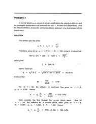
MECHANICS of FLUIDS LABORATORY - Mechanical Engineering
MECHANICS of FLUIDS LABORATORY - Mechanical Engineering
MECHANICS of FLUIDS LABORATORY - Mechanical Engineering

You also want an ePaper? Increase the reach of your titles
YUMPU automatically turns print PDFs into web optimized ePapers that Google loves.
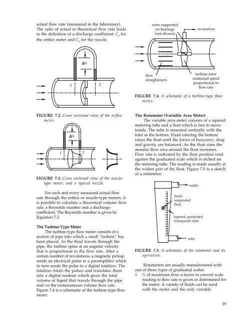
actual flow rate (measured in the laboratory).<br />
The ratio <strong>of</strong> actual to theoretical flow rate leads<br />
to the definition <strong>of</strong> a discharge coefficient: C o<br />
for<br />
the orifice meter and C n<br />
for the nozzle.<br />
rotor supported<br />
on bearings<br />
(not shown)<br />
to receiver<br />
h<br />
1 2<br />
flow<br />
straighteners<br />
turbine rotor<br />
rotational speed<br />
proportional to<br />
flow rate<br />
FIGURE 7.4. A schematic <strong>of</strong> a turbine-type flow<br />
meter.<br />
FIGURE 7.2. Cross sectional view <strong>of</strong> the orifice<br />
meter.<br />
h<br />
1 2<br />
FIGURE 7.3. Cross sectional view <strong>of</strong> the nozzletype<br />
meter, and a typical nozzle.<br />
For each and every measured actual flow<br />
rate through the orifice or nozzle-type meters, it<br />
is possible to calculate a theoretical volume flow<br />
rate, a Reynolds number and a discharge<br />
coefficient. The Reynolds number is given by<br />
Equation 7.2.<br />
The Turbine-Type Meter<br />
The turbine-type flow meter consists <strong>of</strong> a<br />
section <strong>of</strong> pipe into which a small “turbine” has<br />
been placed. As the fluid travels through the<br />
pipe, the turbine spins at an angular velocity<br />
that is proportional to the flow rate. After a<br />
certain number <strong>of</strong> revolutions, a magnetic pickup<br />
sends an electrical pulse to a preamplifier which<br />
in turn sends the pulse to a digital totalizer. The<br />
totalizer totals the pulses and translates them<br />
into a digital readout which gives the total<br />
volume <strong>of</strong> liquid that travels through the pipe<br />
and/or the instantaneous volume flow rate.<br />
Figure 7.4 is a schematic <strong>of</strong> the turbine type flow<br />
meter.<br />
The Rotameter (Variable Area Meter)<br />
The variable area meter consists <strong>of</strong> a tapered<br />
metering tube and a float which is free to move<br />
inside. The tube is mounted vertically with the<br />
inlet at the bottom. Fluid entering the bottom<br />
raises the float until the forces <strong>of</strong> buoyancy, drag<br />
and gravity are balanced. As the float rises the<br />
annular flow area around the float increases.<br />
Flow rate is indicated by the float position read<br />
against the graduated scale which is etched on<br />
the metering tube. The reading is made usually at<br />
the widest part <strong>of</strong> the float. Figure 7.5 is a sketch<br />
<strong>of</strong> a rotameter.<br />
freely<br />
suspended<br />
float<br />
outlet<br />
tapered, graduated<br />
transparent tube<br />
inlet<br />
FIGURE 7.5. A schematic <strong>of</strong> the rotameter and its<br />
operation.<br />
Rotameters are usually manufactured with<br />
one <strong>of</strong> three types <strong>of</strong> graduated scales:<br />
1. % <strong>of</strong> maximum flow–a factor to convert scale<br />
reading to flow rate is given or determined for<br />
the meter. A variety <strong>of</strong> fluids can be used<br />
with the meter and the only variable<br />
19