MECHANICS of FLUIDS LABORATORY - Mechanical Engineering
MECHANICS of FLUIDS LABORATORY - Mechanical Engineering
MECHANICS of FLUIDS LABORATORY - Mechanical Engineering

You also want an ePaper? Increase the reach of your titles
YUMPU automatically turns print PDFs into web optimized ePapers that Google loves.
EXPERIMENT 16<br />
MEASUREMENT OF VELOCITY<br />
AND<br />
CALIBRATION OF A METER FOR COMPRESSIBLE FLOW<br />
The objective <strong>of</strong> this experiment is to<br />
determine a calibration curve for a meter placed<br />
in a pipe that is conveying air. The meters <strong>of</strong><br />
interest are an orifice meter and a venturi meter.<br />
These meters are calibrated in this experiment by<br />
using a pitot-static tube to measure the velocity,<br />
from which the flow rate is calculated.<br />
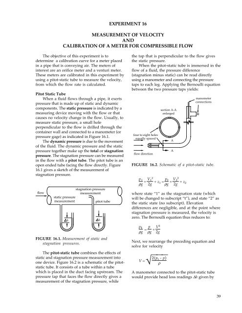
Pitot Static Tube<br />
When a fluid flows through a pipe, it exerts<br />
pressure that is made up <strong>of</strong> static and dynamic<br />
components. The static pressure is indicated by a<br />
measuring device moving with the flow or that<br />
causes no velocity change in the flow. Usually, to<br />
measure static pressure, a small hole<br />
perpendicular to the flow is drilled through the<br />
container wall and connected to a manometer (or<br />
pressure gage) as indicated in Figure 16.1.<br />
The dynamic pressure is due to the movement<br />
<strong>of</strong> the fluid. The dynamic pressure and the static<br />
pressure together make up the total or stagnation<br />
pressure. The stagnation pressure can be measured<br />
in the flow with a pitot tube. The pitot tube is an<br />
open ended tube facing the flow directly. Figure<br />
16.1 gives a sketch <strong>of</strong> the measurement <strong>of</strong><br />
stagnation pressure.<br />
flow<br />
stagnation pressure<br />
measurement<br />
static pressure<br />
measurement<br />
pitot tube<br />
h<br />
FIGURE 16.1. Measurement <strong>of</strong> static and<br />
stagnation pressures.<br />
The pitot-static tube combines the effects <strong>of</strong><br />
static and stagnation pressure measurement into<br />
one device. Figure 16.2 is a schematic <strong>of</strong> the pitotstatic<br />
tube. It consists <strong>of</strong> a tube within a tube<br />
which is placed in the duct facing upstream. The<br />
pressure tap that faces the flow directly gives a<br />
measurement <strong>of</strong> the stagnation pressure, while<br />
h<br />
the tap that is perpendicular to the flow gives<br />
the static pressure.<br />
When the pitot-static tube is immersed in the<br />
flow <strong>of</strong> a fluid, the pressure difference<br />
(stagnation minus static) can be read directly<br />
using a manometer and connecting the pressure<br />
taps to each leg. Applying the Bernoulli equation<br />
between the two pressure taps yields:<br />
four to eight holes<br />
equally spaced<br />
flow direction<br />
section A-A<br />
enlarged<br />
A<br />
A<br />
manometer<br />
connections<br />
FIGURE 16.2. Schematic <strong>of</strong> a pitot-static tube.<br />
p 1<br />
ρg + V 1 2<br />
2g + z 1 = p 2<br />
ρg + V 2 2<br />
2g + z 2<br />
where state “1” as the stagnation state (which<br />
will be changed to subscript “t”), and state “2” as<br />
the static state (no subscript). Elevation<br />
differences are negligible, and at the point where<br />
stagnation pressure is measured, the velocity is<br />
zero. The Bernoulli equation thus reduces to:<br />
p t<br />
ρg = p ρg + V2<br />
2g<br />
Next, we rearrange the preceding equation and<br />
solve for velocity<br />
V =<br />
√⎺⎺⎺<br />
2(p t - p)<br />
ρ<br />
A manometer connected to the pitot-static tube<br />
would provide head loss readings ∆h given by<br />
39