MECHANICS of FLUIDS LABORATORY - Mechanical Engineering
MECHANICS of FLUIDS LABORATORY - Mechanical Engineering
MECHANICS of FLUIDS LABORATORY - Mechanical Engineering

Create successful ePaper yourself
Turn your PDF publications into a flip-book with our unique Google optimized e-Paper software.
Develop a hydraulic jump in the channel;<br />
record upstream and downstream heights,<br />
manometer readings (from which the actual<br />
volume flow rate is obtained) and the lost energy<br />
E. By varying the flow rate, upstream height,<br />
downstream height and/or the channel slope,<br />
record measurements on different jumps. Derive<br />
the applicable equations in detail and substitute<br />
appropriate values to verify the predicted<br />
downstream height and lost energy. In other<br />
words, the downstream height <strong>of</strong> each jump is to<br />
be measured and compared to the downstream<br />
height calculated with Equation 14.1. The same<br />
is to be done for the rate <strong>of</strong> energy loss (Equation<br />
14.2).<br />
Analysis<br />
Data on a hydraulic jump is usually specified<br />
in two ways both <strong>of</strong> which will be required for<br />
the report. Select any <strong>of</strong> the jumps you have<br />
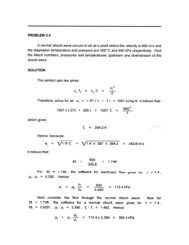
measurements for and construct a momentum<br />
diagram . A momentum diagram is a graph <strong>of</strong><br />
liquid depth on the vertical axis vs momentum on<br />
the horizontal axis. The momentum <strong>of</strong> the flow is<br />
given by:<br />
M = 2Q2<br />
gb 2 h + h2<br />
4<br />
Another significant graph <strong>of</strong> hydraulic jump<br />
data is <strong>of</strong> depth ratio h 2 /h 1 (vertical axis) as a<br />
function <strong>of</strong> the upstream Froude number, Fr 1 (=<br />
Q 2 /gb 2 h 1<br />
3<br />
). Construct such a graph for any <strong>of</strong> the<br />
jumps for which you have taken measurements.<br />
35