Aircraft Exhaust Systems IV - CAFE Foundation
Aircraft Exhaust Systems IV - CAFE Foundation
Aircraft Exhaust Systems IV - CAFE Foundation

You also want an ePaper? Increase the reach of your titles
YUMPU automatically turns print PDFs into web optimized ePapers that Google loves.
AIRCRAFT RESEARCH REPORT<br />
Sponsored and Funded by the Experimental <strong>Aircraft</strong> Association<br />
and the Federal Aviation Administration<br />
TRIAVIATHON<br />
TROPHY<br />
<strong>CAFE</strong><br />
FOUNDATION<br />
PRESIDENT<br />
Brien Seeley<br />
VICE<br />
PRESIDENT<br />
Larry Ford<br />
TREASURER<br />
C.J. Stephens<br />
SECRETARY<br />
Daniel Wayman<br />
TEST PILOTS<br />
C.J. Stephens<br />
DIRECTORS<br />
Crandon Elmer<br />
Otis Holt<br />
Jack Norris<br />
Cris Hawkins<br />
Stephen Williams<br />
Ed Vetter<br />
CHALLENGE<br />
TROPHY<br />
T<br />
<strong>Aircraft</strong> <strong>Exhaust</strong><br />
<strong>Systems</strong> <strong>IV</strong><br />
he goal of this report<br />
is to facilitate the improvement<br />
of the<br />
power, efficiency and reliability<br />
of aircraft exhaust systems.<br />
The report summarizes the results<br />
of a 16 month long study.<br />
Many of the systems tested<br />
here are similar to ones popularly<br />
used in light aircraft.<br />
The tests include 4 into 1 collector<br />
systems, 4 into 2<br />
“crossover” systems, “Tri-Y”<br />
systems and independent exhaust<br />
stacks. Additional<br />
aspects of exhaust design in<br />
this study are:<br />
Intake waves<br />
Wave speed<br />
Megaphone effects<br />
RPM effects<br />
<strong>Exhaust</strong> jet thrust<br />
Crossover/Tri-Y reflections<br />
Frequency analysis (FFT’s)<br />
Header size<br />
Collector size<br />
Coanda nozzles<br />
Bends in the pipe<br />
EGT and CHT effects<br />
Ball joint effects<br />
Over 350 separate <strong>Exhaust</strong><br />
Pressure Graph (EPG)<br />
recordings were made using<br />
the Lycoming IO-360 A1B6<br />
engine in the <strong>CAFE</strong> test-bed<br />
Mooney M20E. All of these<br />
were made at 125’ MSL as static<br />
ground engine runs of<br />
approximately 15 seconds duration.<br />
BY BRIEN A. SEELEY AND ED VETTER<br />
<strong>CAFE</strong>, EAA and the FAA<br />
are grateful to the following<br />
major contributors to this<br />
study: Aerospace Welders of<br />
Minneapolis for the high quality<br />
exhaust merges and ball<br />
joints, George Johnston of<br />
EAA Chapter 124 for the<br />
lathe-machined model of the<br />
Coanda nozzle, Sam Davis at<br />
Tube Technologies in Corona,<br />
California for the stainless<br />
steel exhaust system derived<br />
from thes tests, and Bill Cannam,<br />
a certified welder from<br />
EAA Chapter 124, for the major<br />
effort to assemble the<br />
stainless steel exhaust system.<br />
Curt Leaverton, Jack Norris,<br />
Andy Bauer and Steve<br />
Williams each contributed<br />
professional scientific analysis<br />
of the EPG’s.<br />
ABBREVIATIONS<br />
EVO = exhaust valve opening<br />
EVC = exhaust valve closure<br />
<strong>IV</strong>O = intake valve opening<br />
<strong>IV</strong>C = intake valve closure<br />
TDC = top dead center<br />
BDC = bottom dead center<br />
W.O.T. = wide open throttle<br />
gph = gallons per hour<br />
dB = decibels, slow A scale<br />
FFT = fast Fourier transform<br />
cyl = cylinder<br />
coll. = collector<br />
msec. = milliseconds<br />
Hz. = Hertz or cycles per sec<br />
“Hg. = inches of Mercury<br />
O.D. = outside diameter<br />
File 411<br />
Coanda nozzle<br />
Pipe merges<br />
Ball joints<br />
Crossover<br />
modeling
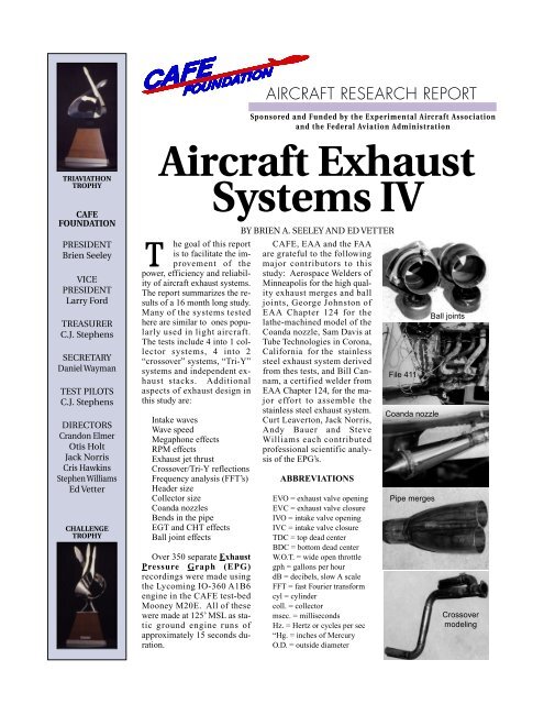
THE BASIC EPG<br />
A Review<br />
Figure 1 shows a basic EPG. It was<br />
recorded on a well-tuned 4 into 1 collector<br />
exhaust system which will be<br />
hereafter referred to as “File 411”.<br />
Figure 1 shows features which are essential<br />
for understanding the other<br />
graphs in this report. The “X” axis,<br />
along the bottom of the graph, shows<br />
the degrees of crankshaft rotation beginning<br />
at top dead center (TDC) of<br />
the firing stroke for cylinder #1. The<br />
vertical “Y” axis shows the pressure<br />
measured in the pipe in inches of Hg.<br />
Since these runs were made at near sea<br />
level, the zero pressure level represents<br />
ambient pressure of about 30.00” Hg.<br />
The typical EPG shows a steeply<br />
rising “P” wave of exhaust pressure,<br />
shown in red, which starts upward at<br />
the point of exhaust valve opening<br />
(EVO). The tall P wave typically falls<br />
to below zero (ambient) pressure later<br />
in the exhaust cycle.<br />
The intake pressure is shown in<br />
blue. There is a black vertical dotted<br />
line at BDC after the intake stroke,<br />
where the piston’s descent ceases.<br />
The amount of valve lift of the exhaust<br />
and intake valves is shown at the<br />
bottom of the graph. At overlap TDC,<br />
both valves are open for a brief interval.<br />
The EPG often shows additional<br />
waves which come from reflections,<br />
turbulence and, in collector-equipped<br />
systems, the firings of the other cylinders<br />
(cross-talk). These are labeled by<br />
their cylinder of origin as the R waves<br />
in Figure 1.<br />
The C waves are those measured in<br />
the collector, the common pipe into<br />
which are merged the individual headers.<br />
Each cylinder produces a separate<br />
C wave. The time, “T”, shown in Figure<br />
1 between the rise of the P wave<br />
and the rise of the attendant C wave, is<br />
very short and can be used to calculate<br />
the velocity of the wave.<br />
The “blowdown” cycle is defined<br />
as the period from EVO to firing BDC,<br />
and is labeled “B”. It is during this interval<br />
that the steep rise of the P wave<br />
is seen, as the cylinder discharges or<br />
‘blows down’ through the exhaust<br />
valve and the in-cylinder pressure<br />
rapidly falls . Positive in-cylinder<br />
pressure during blowdown is still doing<br />
some useful work by pushing<br />
downward on the piston.<br />
Pressure, inches Hg.<br />
Files 411 Basic EPG: 4 into 1 as 1.75x34.5x2.25x19.5 equal length headers. 29.5" M.P.,<br />
2731 RPM 20.4 gph 86°F. 8-18-96. 125' MSL. Lycoming IO-360 A1B6 firing order: 1324<br />
See text for explanation of P, C, S and R waves shown below.<br />
40<br />
411 Cyl #1 411 Cyl #2 411 Intake 411 Collector Wave<br />
30<br />
20<br />
10<br />
0<br />
-10<br />
-20<br />
Both cylinders #1 and #2 show low opening<br />
pressures at EVO and very low pressure<br />
3 1<br />
P<br />
P<br />
1 during overlap TDC. Some scavenging of 2<br />
4 2<br />
the intake trace appears to occur. The P<br />
wave (red) goes negative early in the<br />
Aft looking view<br />
exhaust cycle.<br />
of collector entry<br />
C 1 C 2<br />
Intake<br />
C<br />
scavenge 3<br />
R 4<br />
begins here<br />
R 2<br />
B<br />
R 3<br />
+S<br />
EVO<br />
#1<br />
<strong>Exhaust</strong> BDC<br />
<strong>Exhaust</strong> Valve<br />
-S<br />
360<br />
Intake Valve<br />
EVC<br />
#1<br />
240<br />
120<br />
0<br />
0 30 60 90 120 150 180 210 240 270 300 330 360 390 420 450 480 510 540 570 600<br />
T<br />
Overlap TDC<br />
Crankshaft Degrees After Firing TDC<br />
Intake BDC<br />
EVO<br />
#2<br />
Overlap TDC is a very important<br />
interval. When both the exhaust and<br />
intake valves are open, the pressures in<br />
the exhaust pipe, combustion chamber<br />
and intake tract can all influence one<br />
another. How much influence depends<br />
upon the valve lift during overlap and<br />
how long both valves remain open.<br />
During overlap TDC, the suction in<br />
a tuned exhaust’s header can help<br />
empty the combustion chamber of its<br />
burnt gas residues. This effect is called<br />
“scavenging”. The exhaust suction<br />
may even enhance the combustion<br />
chamber’s filling from the intake valve,<br />
thus improving volumetric efficiency<br />
and horsepower. With sufficiently<br />
long overlap intervals, it is possible for<br />
the suction to pull some cool intake<br />
charge across the hot exhaust valve,<br />
cooling the valve face, stem, seat and<br />
guide. Such cooling comes at a price,<br />
which is that raw fuel is being wasted<br />
out the exhaust pipe. Higher compression<br />
pistons should scavenge better<br />
due to their smaller combustion chamber<br />
volume.<br />
Note that in Figure 1, the intake<br />
pressure is greater than the exhaust<br />
pressure at overlap TDC. Such a pressure<br />
gradient will encourage scavenging.<br />
At part throttle, the intake<br />
pressure would be much lower, and unfavorable<br />
reverse flow could occur at<br />
overlap. This is one argument for using<br />
wide open throttle (W.O.T.)<br />
whenever possible in high altitude<br />
cruise flight.<br />
PUMPING GAS<br />
Figure 1<br />
cylinder<br />
filling<br />
ends<br />
Valve Lift, inches/1000<br />
Normally, engine designers try to<br />
place EVO about 40-75° prior to firing<br />
BDC so that the peak of the very high<br />
in-cylinder pressure can be dissipated<br />
during blowdown, before BDC. A<br />
tuned exhaust system, with a very low<br />
opening pressure at EVO, can assist in<br />
evacuating the cylinder quickly, and<br />
can thus allow EVO to be delayed until<br />
later in the cycle. The later EVO allows<br />
the positive in-cylinder pressure<br />
to do more work pushing the piston<br />
downward prior to EVO. Thus, a tuned<br />
exhaust system works best if the timing<br />
of EVO is delayed to take<br />
advantage of the tuning.<br />
After blowdown in the exhaust<br />
stroke, the piston begins to rise from<br />
BDC. A rising piston pushing against
a high in-cylinder pressure causes a<br />
loss of power known as a “pumping<br />
loss”. Ideally, the rising piston would<br />
be pulled upward by a negative pressure<br />
in the cylinder, thus producing a<br />
“pumping gain”. Suction in a tuned<br />
exhaust system can produce such a<br />
pumping gain in mid to late exhaust<br />
stroke. This is shown in Figure 1<br />
where the exhaust pressure goes negative<br />
at 260° of crank angle, which is<br />
80° after BDC. The earlier in the exhaust<br />
cycle that the P wave subsides<br />
and goes negative or below the ambient<br />
(zero) pressure, the more pumping<br />
gain can occur, making for greater<br />
horsepower.<br />
Thus, an ideal exhaust system<br />
should produce a highly negative<br />
pressure at the exhaust valve at both<br />
EVO and again as soon as possible<br />
after dissipating the P wave. This<br />
negative pressure should be made to<br />
persist throughout the overlap stroke<br />
so that favorable scavenging can occur.<br />
INTAKE PULSATIONS<br />
The piston’s descent during each intake<br />
stroke exerts strong suction on the<br />
intake pipe runner connecting the carburetor<br />
to the cylinder. If all of the<br />
intake runners attach to a common<br />
plenum, as in the Lycoming engines,<br />
the suction will affect all of those runners.<br />
The suction causes a flow to be<br />
initiated in one direction which is<br />
abruptly stopped when the intake valve<br />
closes. The flow stoppage creates a reflecting<br />
wave which again affects all of<br />
the runners. This leads to intake pulsations.<br />
The intake pulsations on the Lycoming<br />
IO-360 A1B6 engine are<br />
sizable and can be seen in Figure 1.<br />
These pulsations can show how much<br />
scavenging effect might be expected,<br />
and the character of the cylinder filling.<br />
The latter can serve as a guide to<br />
the relative volumetric efficiency of<br />
the engine.<br />
The W.O.T. intake pulse can reach<br />
as high as 6-7” Hg. above atmospheric<br />
pressure, as seen at “+S” in Figure 1.<br />
This effect thus gives an instantaneous<br />
manifold pressure of about 37” Hg.,<br />
and, if timed correctly, can act somewhat<br />
like supercharging. Ideally, the<br />
lowest point in the intake pulsation<br />
trough should be timed to occur at “-<br />
S” or about 60° after overlap TDC.<br />
Pressure, inches Hg.<br />
Files 411/413 The effect of a megaphone: 4 into 1 as 1.75x34.5x2.25x19.5 equal length<br />
headers. File 413 has a 17Lx2.25x4" megaphone added to 411. Both at 29.5" M.P.<br />
(W.O.T.), 86°F. 8-18-96. Lycoming IO-360 A1B6 firing order:1324 Run at 125' MSL.<br />
40<br />
#411 2731 RPM 20.4 gph 106.9 dB, no meg<br />
30<br />
20<br />
10<br />
0<br />
-10<br />
-20<br />
3 1<br />
4 2<br />
Aft looking view<br />
of collector entry<br />
EVO<br />
<strong>Exhaust</strong> Valve<br />
360<br />
240<br />
Intake Valve<br />
120<br />
0<br />
0 30 60 90 120 150 180 210 240 270 300 330 360 390 420 450 480 510 540 570 600<br />
This will tend to assure that the next<br />
positive pulse will arrive just prior to<br />
<strong>IV</strong>C, enhancing flow through the intake<br />
valve just as cylinder filling ends.<br />
Yagi et al 17 have written an excellent<br />
paper on using induction system<br />
pulsations to force feed the engine’s<br />
cylinder during the intake stroke.<br />
We did not observe any pressure<br />
pulses in the intake waves attributable<br />
to the propeller blade sweeping past<br />
the air cleaner intake. However, these<br />
tests had the air intake located 11-12”<br />
aft of the propeller disc. On those<br />
cowlings with a very far forward air<br />
cleaner intake, the EPG may be able to<br />
detect whether the prop is producing a<br />
pulse into the air cleaner at just the<br />
right moment during the intake cycle.<br />
WAVE SPEED<br />
The EPG can show the average<br />
speed of a wave traveling through the<br />
pipe. The wave speeds observed actually<br />
represent the sum of the average<br />
sonic wave speed and the average mass<br />
flow velocity.<br />
A test using sensors 21.5” apart on<br />
a 1.625” primary header showed an average<br />
wave speed of 1751 fps.<br />
P<br />
Firing BDC<br />
#411 intake pressure, no meg<br />
#413 2737 RPM 20.6 gph 107.8 dB, with meg<br />
#413 intake pressure, with meg<br />
The megaphone can increase power by<br />
lowering the opening pressure at EVO, and<br />
scavenging more at overlap. The noise level<br />
is significantly higher, however.<br />
Overlap TDC<br />
Crankshaft Degrees After Firing TDC<br />
Intake BDC<br />
R<br />
R 2<br />
3<br />
cylinder<br />
filling<br />
concludes<br />
Figure 2<br />
In Figure 1, the time interval “T”<br />
represents the time for the 2731 RPM<br />
P wave to reach the collector tap from<br />
the top of the header, a distance of<br />
47.0". This computes to about 1604<br />
fps average speed. This slower speed<br />
suggests that some slowing occurs as<br />
the header wave enters the collector.<br />
File 412, at 2507 RPM, showed an<br />
average wave speed of 1508 fps, a<br />
7.5% reduction from an 8% reduction<br />
in RPM. The reduced speed is due to a<br />
lower EGT and the slower average piston<br />
speed which gives a slower mass<br />
flow.<br />
The exhaust gas expands and cools<br />
as it goes down the pipe, and the wave<br />
velocity varies directly with the square<br />
root of the ratio of the absolute exhaust<br />
gas temperatures.<br />
MEGAPHONE EFFECTS<br />
Valve Lift, inches/1000<br />
Figure 2 shows that a megaphone<br />
added to file 411 produced a lowering<br />
of the opening pressure at EVO and<br />
better scavenging at the expense of<br />
more noise. A megaphone was later<br />
added to a Tri-Y system and showed<br />
minimal influence on the EPG.
THE EPG TEST METHOD<br />
The EPG pressure sensor was connected<br />
to a 9” long copper tube of 0.125”<br />
O.D. flush-mounted to the header pipe’s inner<br />
wall. The mounting was at a point<br />
1.25” downstream of the cylinder head<br />
flange. The signals were processed by the<br />
Vetter Sensor Acquisition Module and<br />
Digital Acquisition Device. Sensors were<br />
calibrated using a water manometer.<br />
A new amplifier was used for this study.<br />
Its faster response time and higher resolution<br />
provided a much better picture of the<br />
EPG relative to those in previous reports.<br />
1,2,3<br />
The intake pressure recordings were<br />
made 1.5” upstream of the intake valve<br />
through the fuel injector port in the Lycoming<br />
cylinder head.<br />
RPM, noise level, static thrust in<br />
pounds, fuel flow, wind incident to the<br />
propeller and manifold pressure were<br />
recorded manually. Variations in the RPM,<br />
EGT, CHT and mixture were used on several<br />
runs to study their effects.<br />
In all of the EPG’s shown here, the timing<br />
of the waves with respect to the<br />
crankshaft degrees has been shifted to the<br />
left (earlier) by 1.25 milliseconds to compensate<br />
for a) the 12 inch distance which<br />
separates the pressure sensor and the exhaust<br />
valve face (1.0 millisecond), b) the<br />
electronic rise time of the pressure sensor<br />
(0.15 milliseconds) and c) the amplifier<br />
delay (0.10 milliseconds). This places the<br />
wave timing at its correct phasing with the<br />
valve opening cycles.<br />
Fast Fourier transforms (FFT’s) were<br />
made on each of the runs to look at the<br />
sonic frequencies which had the greatest<br />
energy content. Analyzing these transforms<br />
exceeds the scope of this report.<br />
See the bibliography for several references<br />
on wave theory.<br />
Noise levels were taken from the area<br />
between the front seats of the aircraft with<br />
the pilot’s side vent window open using the<br />
A scale slow setting. Noise was reduced<br />
when the tailpipe exit was moved aftward<br />
relative to the noise meter, as occurred<br />
with the longest tailpipes.<br />
Peak RPM and fuel flow generally correlated<br />
with the thrust values and were<br />
used as a rough guide to power output.<br />
The anemometer showed a change in local<br />
wind speed and direction as the propeller’s<br />
flow field reached full strength at maximum<br />
static RPM. This flow was allowed<br />
to equilibrate before the RPM and fuel<br />
flow readings were taken.<br />
Pressure, inches Hg.<br />
Pressure, inches Hg.<br />
Files 502/422/510: Varied collector diameters. All use the same 4 nto 1, equal length<br />
headers of: 1.75x34.5 with ~30" collector length. 73-82°F. 8-24-96. Lycoming IO-360<br />
A1B6 firing order:1324 Run at 125' MSL.<br />
40<br />
2x29" C 19.7 gph 2635 RPM #502<br />
30<br />
20<br />
10<br />
0<br />
-10<br />
-20<br />
Files 411, 415, 419, 422, and 424 to compare different collector lengths. All use the same 4<br />
into 1, equal length headers as: 1.75x34.5 with a 2.25" diameter collector. 78-86°F. 8-18-<br />
96. Lycoming IO-360 A1B6 firing order:1324 Run at 125' MSL.<br />
40<br />
EVO, blowdown<br />
49.5" 20.2 gph 2666 RPM #415<br />
and overlap<br />
pressures all<br />
#415 Intake<br />
change as collector<br />
length is altered.<br />
29.5" 20.3 gph 2687 RPM #422<br />
Fuel flows and<br />
30<br />
#422 Intake<br />
RPM's, suggest the<br />
19.5" or<br />
19.5" 20.4 gph 2731 RPM #411<br />
29.5"collector as<br />
optimal. Intakes<br />
#411 Intake<br />
show only minor<br />
10" 20.2 gph 2700 RPM #424<br />
changes due to<br />
20 limited valve<br />
#424 Intake<br />
overlap.<br />
10<br />
0<br />
-10<br />
-20<br />
The 2.25" collector<br />
seems optimal.<br />
EVO<br />
<strong>Exhaust</strong> Valve<br />
360<br />
Intake Valve<br />
240<br />
120<br />
0<br />
0 30 60 90 120 150 180 210 240 270 300 330 360 390 420 450 480 510 540 570 600<br />
<strong>Exhaust</strong> BDC<br />
#502 Intake<br />
2.25x30" C 20.3 gph 2687 RPM #422<br />
#422 Intake<br />
2.5x30" C 19.9 gph 2669 RPM #510<br />
#510 Intake<br />
Multiple small waves in<br />
#502 may<br />
be due to multiple slip<br />
joints used.<br />
Crankshaft Degrees After Firing TDC<br />
<strong>Exhaust</strong> Valve<br />
360<br />
240<br />
Intake Valve<br />
120<br />
0<br />
0 30 60 90 120 150 180 210 240 270 300 330 360 390 420 450 480 510 540 570 600<br />
Overlap TDC<br />
Overlap TDC<br />
Crankshaft Degrees After Firing TDC<br />
3 1<br />
4 2<br />
Aftward view of<br />
collector entry<br />
geometry by<br />
cylinder #<br />
Intake BDC<br />
Intake BDC<br />
Figure 3<br />
Valve Lift, inches/1000<br />
Valve Lift, inches/1000<br />
Figure 4
BENDS IN THE PIPE<br />
File 411’s header pipe bends were<br />
as follows:<br />
Cyl #1: 25° + 90° + 170° = 285°<br />
Cyl #2: 85° + 90° + 90° = 265°<br />
Cyl #3: 35° + 170° + 180° = 385°<br />
Cyl #4: 80° + 70° + 20° = 170°<br />
Individual testing of these separate<br />
cylinders did not show any significant<br />
changes in their EPG waveforms. See<br />
Figure 1, cylinders #1 and #2.<br />
Many aircraft use a downward bend<br />
in the tailpipe to keep exhaust soot off<br />
the aircraft’s belly. Keeping collector<br />
length constant, files 502 (a straight<br />
2x29” collector), 503 (2x29” with a<br />
90° bend at the exit), and 504 (1.5”<br />
nozzle on a straight 2x29” collector)<br />
were tested at W.O.T. The results were<br />
EVO opening pressures of -5.0, -4.0<br />
and +3.0, respectively with overlap<br />
pressures of -10.0, -10.0, and -4.0, respectively.<br />
The P wave width remained<br />
the same.<br />
File 503, with a 90° downward<br />
bend of the collector at the exit, caused<br />
an insignificant increase in backpressure.<br />
The nozzle did impose a<br />
significant backpressure penalty.<br />
COLLECTOR SIZE<br />
See Figure 3. These tests repeatedly<br />
showed that, for this particular<br />
engine, the 2.25” diameter collector<br />
was best for optimizing exhaust backpressure<br />
at sea level. A 2.125”<br />
diameter collector would probably give<br />
a good compromise between climb<br />
power and high altitude jet thrust.<br />
See Figure 4 and 6. Collector<br />
length appeared to optimize at 20-30”.<br />
It must be long enough to develop<br />
some continuum of flow and fully contain<br />
each pulse.<br />
COLLECTOR EFFECTS<br />
See Figure 5. The addition of a<br />
collector to 4 separate independent<br />
pipes consistently caused the entire<br />
EPG to shift to lower, more negative<br />
pressures. Some suspect that this effect<br />
may be caused by the more<br />
continuous mass flow in the collector<br />
exerting a prolonged vacuum effect<br />
upon all of the headers. A suitable collector<br />
was one with about 50-90%<br />
greater cross sectional area than each<br />
individual header and with a length of<br />
Pressure, inches Hg.<br />
Pressure, inches Hg.<br />
Files 723/724/725 RPM effects: All of these headers are 1.625x28" with no collector except file 411<br />
which is 1.75x34.5x2.25x19.5. All at 97°F except 411 at 86°F. Lycoming IO-360 A1B6 firing<br />
order:1324 at 125' MSL..<br />
40<br />
6" stub Cyl #4 @2670 RPM #727<br />
30<br />
20<br />
10<br />
0<br />
-10<br />
-20<br />
0<br />
-10<br />
-20<br />
<strong>Exhaust</strong> Valve<br />
Intake Valve<br />
<strong>Exhaust</strong> BDC<br />
28" Cyl #3 @ 2710 RPM #723<br />
45.5" Cyl #3 @ 2670 RPM #727<br />
68" Cyl #3 @ 2700 RPM #728<br />
34.5" + collector @ 2731 RPM #411<br />
The 45.5" and 68" long headers each<br />
have too broad a P wave that delays<br />
their negative wave. All of the<br />
independent headers (no collector)<br />
show characteristic "ringing" waves<br />
following the P wave. The 6" stub is<br />
too short to contain a fully developed<br />
P wave. A collector equipped system<br />
(#411) shows much improved tuning.<br />
0 30 60 90 120 150 180 210 240 270 300 330 360 390 420 450 480 510 540 570 600 630 660<br />
Overlap TDC<br />
Crankshaft Degrees After Firing TDC<br />
Files 419/420/421/412/425 RPM and collector length effects: All headers are 1.75x34.5". Files 419,<br />
420, and 421 used a 2.25x40" collector. File 412 used a 2.25x19.5" and file 425 used a 2.25x10"<br />
collector. All at 78-86°F. Lycoming IO-360 A1B6 firing order: 1324 at 125' MSL..<br />
40<br />
At 2500 RPM,<br />
2672 RPM, 20.0 gph, 105.4 dB, #419<br />
shortening the<br />
collector has<br />
2501 RPM, 15.2 gph, 103.2 dB, #420<br />
little effect on<br />
both the P<br />
2507 RPM, 106.3 dB, 19.5" coll., #412<br />
30<br />
wave timing<br />
and the intake<br />
waves. The<br />
2504 RPM, 14.4 gph, 105.8 dB, 10" coll., #425<br />
10" collector<br />
shows higher<br />
2289 RPM, 11.3 gph, 100.2 dB, #421<br />
pressure at<br />
EVO and<br />
20<br />
during<br />
blowdown and<br />
overlap. Lower<br />
RPM gives<br />
smaller P<br />
waves which<br />
10<br />
go negative<br />
earlier in the<br />
exhaust cycle.<br />
<strong>Exhaust</strong> Valve<br />
Intake Valve<br />
<strong>Exhaust</strong> BDC<br />
80 100 120 140 160 180 200 220 240 260 280 300 320 340 360 380 400<br />
Crankshaft Degrees After Firing TDC<br />
Overlap TDC<br />
Figure 5<br />
Valve Lift, inches/1000<br />
Valve Lift, inches/1000<br />
360<br />
240<br />
120<br />
0<br />
Figure 6<br />
360<br />
240<br />
120<br />
0
Pressure, inches Hg.<br />
X b<br />
Files 729/730/731/732 Crossover systems of various blind leg lengths. Cyl #1 has a<br />
1.625x28" primary header except in 732 where it is 45.5" long. The blind offtake is 2.5"<br />
downstream of #1 cyl head. 97°F Lycoming IO-360 A1B6 firing order:1324 at 125' MSL.<br />
Note how blind end pressures are reflected back into the header to alter timing.<br />
40<br />
Cyl #1<br />
729 cyl #1 28" with 67" blind<br />
Cyl #1 Sensor<br />
730 cyl #1 28" with 51.5" blind<br />
731 cyl #1 28" with 36.5" blind<br />
30<br />
732 cyl #1 45.5" with 36.5" blind<br />
729 67" blind end<br />
731 36.5" blind end<br />
731 has the best combination<br />
of low pressure during the<br />
20<br />
exhaust cycle and good<br />
Blind end<br />
scavenge at overlap. None of<br />
Sensor<br />
these systems shows the low<br />
X opening pressure at EVO or<br />
1 the mid cycle pumping gains<br />
10<br />
found with the 4 into 1 collector<br />
systems.<br />
0<br />
Figure 7<br />
Pressure, inches Hg.<br />
-10<br />
-20<br />
30<br />
20<br />
10<br />
0<br />
-10<br />
-20<br />
<strong>Exhaust</strong> Valve<br />
<strong>Exhaust</strong> BDC<br />
N b<br />
N 1<br />
Intake Valve<br />
360<br />
240<br />
120<br />
0<br />
0 30 60 90 120 150 180 210 240 270 300 330 360 390 420 450 480 510 540 570 600<br />
OverlapTDC<br />
Crankshaft Degrees After Firing TDC<br />
Files 511/516 to compare crossover 4 into 2 versus a Tri-Y system. All use the same equal<br />
length headers as: 1.75x34.5 with 511 having 2 each 1.875"x18" tailpipes and the Tri-Y<br />
having a merging of those 2 tailpipes into a single 18.5x2" outlet. 77-78°F. 8-24-96.<br />
Lycoming IO-360 A1B6 firing order:1324 Run at 125' MSL. Both at W.O.T.<br />
40<br />
#511 4 into 2, Cyl #1<br />
Figure 8<br />
EVO<br />
X<br />
#511 Cyl #2, 2660 RPM 20.0 gph<br />
#516 Tri-Y, Cyl #1<br />
#516 Cyl #2, 2703 RPM 20.5 gph<br />
These two systems show that the main<br />
behavior of the system is related to the<br />
crossover leg length, rather than the<br />
addition of the Tri-Y's tailpipe-collector.<br />
However, the Tri-Y's collector does seem to<br />
shift the entire waveform toward lower<br />
pressures and give higher RPM and fuel<br />
flow. Both systems clearly show the P wave<br />
reflected to cyl #2 at X, and that reflection's<br />
return into the cylinder #1 trace at R.<br />
R<br />
<strong>Exhaust</strong> Valve<br />
360<br />
Intake Valve<br />
240<br />
120<br />
0<br />
0 30 60 90 120 150 180 210 240 270 300 330 360 390 420 450 480 510 540 570 600<br />
Overlap TDC<br />
Crankshaft Degrees After Firing TDC<br />
Valve Lift, inches/1000<br />
Valve Lift, inches/1000<br />
at least 18” or so. See “length formulae”<br />
below.<br />
In Figure 5, the small waves which<br />
occur after the P wave in the independent<br />
pipes are called ‘rings’, as in a<br />
doorbell ringing. The negative portions<br />
of these rings are of such short<br />
duration that they require the pipe designer<br />
to choose between positioning<br />
them early in the cycle to obtain pumping<br />
gains or late in the cycle to<br />
scavenge at overlap. The collector system<br />
has such a long duration negative<br />
wave after the P wave, that it serves<br />
both purposes, i.e., gives pumping<br />
gain as well as scavenging at overlap.<br />
CROSSOVERS AND TRI-Y<br />
A crossover exhaust joins the headers<br />
of cylinders whose firings occur<br />
180 crankshaft degrees apart. The P<br />
wave of one cylinder will then travel<br />
upstream to the other cylinder where it<br />
will bounce off of a closed exhaust<br />
valve and return. Pipe lengths in the<br />
crossover can be chosen so that the returning<br />
wave will produce a negative<br />
pressure for scavenging.<br />
See Figure 7 and 8. Two different<br />
crossover systems were tested. One<br />
was a simulation model in which an<br />
independent header on cylinder #1 had<br />
an offshoot pipe welded on about 2.5”<br />
downstream from the cylinder flange.<br />
The offshoot pipe was a blind leg<br />
whose length could be adjusted and on<br />
the end of which a pressure sensor was<br />
attached, as shown in Figure 7.<br />
The other crossover system (File<br />
511) was 1.75x34.5” headers pairing<br />
cylinder 1 with 2, and 3 with 4. Each<br />
of these pairs of cylinders fire 180°<br />
apart. See Figure 8.<br />
The reflected waves from the blind<br />
leg are powerful and their effect on the<br />
P wave can be clearly seen here. In<br />
Figure 7, X b marks the peak of the P<br />
wave’s arrival in the 67” blind leg of<br />
file 729 in the simulation model. X 1<br />
marks the ill-timed return point of that<br />
peak into the cylinder # 1 pressure<br />
trace. This ruins the tuning. N b marks<br />
the trough in the 36.5” blind leg of file<br />
731. N 1 shows this trough’s return to<br />
the cylinder to help it develop a negative<br />
scavenging wave. This simulator<br />
lacks the influence of cyl #2’s firings.<br />
The crossover system showed better<br />
performance if the length from cylinder<br />
flange to tailpipe exit was 28”<br />
rather than 45”.
Pressure, inches Hg.<br />
Files 516/517/601/603/411: Tri-Y system at differing RPM's. Headers are 1.75x34.5" into<br />
two separate 1.875"x18" intermediates which then merge into a single 2x18.5" collector for<br />
files 516/517 but into a 2x6" collector for files 601/603. Cylinders #1 and #2 are merged<br />
together as are cylinders #3 and #4. File #411 is a 4 into 1 collector system. 78°F. 8-24-<br />
96. Lycoming IO-360 A1B6 firing order: 1324 Run at 125' MSL.<br />
40<br />
2703 RPM 29.7" M.P. 20.5 gph 2x18.5 coll.<br />
30<br />
Figure 9<br />
Pressure, inches Hg.<br />
20<br />
10<br />
0<br />
-10<br />
-20<br />
Files 516/517/518 to compare a Tri-Y system at differing RPM's. All use the same equal<br />
length headers as: 1.75x34.5 with 1.875"x18" intermediates merging into a single 18.5x2"<br />
outlet. 78-79°F. 8-24-96. Lycoming IO-360 A1B6 firing order:1324 Run at 125' MSL.<br />
40<br />
#516 2703 RPM Cyl #1<br />
#517 2476 RPM Cyl #2<br />
30<br />
Figure 10<br />
20<br />
10<br />
0<br />
-10<br />
-20<br />
EVO<br />
<strong>Exhaust</strong> BDC<br />
<strong>Exhaust</strong> Valve<br />
Intake Valve<br />
360<br />
240<br />
120<br />
0<br />
0 30 60 90 120 150 180 210 240 270 300 330 360 390 420 450 480 510 540 570 600 630 660<br />
#516 2703 RPM Cyl #2<br />
#517 2476 RPM Cyl #1<br />
<strong>Exhaust</strong> BDC<br />
2476 RPM 25.0" M.P. 15.2 gph 2x18.5 coll.<br />
2699 RPM 29.8" M.P. 19.9 gph 2x6 coll.<br />
2513 RPM 24.8" M.P. 14.8 gph 2x6 coll.<br />
2731 RPM 29.5" M.P. 20.4 gph File #411<br />
#518 2255 RPM Cyl #1<br />
#518 2255 RPM Cyl #2<br />
Note the way that the cyl #2 trace shows the<br />
arrival of cyl #1's P wave. The pairs of arrows<br />
below show that the negative wave in cyl #2<br />
travels back to cyl #1 and helps lower its pressure<br />
trace. This gives some excellent scavenging at all<br />
of these usable RPM's. Shorter headers would<br />
probably better scavenge the higher RPM's.<br />
360<br />
240<br />
<strong>Exhaust</strong> Valve<br />
120<br />
0<br />
100 120 140 160 180 200 220 240 260 280 300 320 340 360 380 400 420<br />
Overlap TDC<br />
Crankshaft Degrees After Firing TDC<br />
Crankshaft Degrees After Firing TDC<br />
Overlap TDC<br />
Intake BDC<br />
F<br />
Valve Lift, inches/1000<br />
Valve Lift, inches/1000<br />
A commonly used, ‘off-the-shelf’<br />
Lycoming crossover system has 1.75”<br />
O.D. headers wherein cylinders 1 and<br />
2 are joined about 11” downstream of<br />
cylinder 2 and 33” downstream of<br />
cylinder 1. This makes a 44” “blind<br />
leg” or crossover length between those<br />
two cylinders. Cylinders 3 and 4 are<br />
similarly joined. These joined pipes<br />
then each exit through a 2.125”x16”<br />
long tailpipe.<br />
The Tri-Y system in Figure 8 was<br />
1.75x34.5” equal length headers which<br />
merged cylinders 1 with 2 and 3 with 4<br />
into 1.875x18” intermediate pipes.<br />
The intermediates merged into a<br />
2x18.5” collector.<br />
In Figure 9, the Tri-Y showed a<br />
large amount (-15.0” Hg.) of suction<br />
during overlap, but this came at the<br />
sacrifice of both opening pressure and<br />
pumping gain relative to the green<br />
trace of file 411’s 4 into 1 collector. At<br />
lower RPM, a large pumping gain appears<br />
but the scavenge is lost. At “F”<br />
on the graph, a large pressure trace arrives<br />
from cylinder # 2’s P wave<br />
influence. It is the reflection of such<br />
large pressure waves that make the<br />
negative pressures so dramatic in the<br />
Tri-Y and crossover systems.<br />
See Figure 10. This expanded scale<br />
graph shows how the negative waves<br />
in the blind leg of cylinder #2 return<br />
and reduce the pressure in cylinder<br />
#1’s header. See the paired arrows.<br />
The red double-ended arrow shows the<br />
remarkably early onset of negative<br />
pressure at low RPM in this system.<br />
These primary header lengths (34.5”)<br />
seem to be optimal for about 2500<br />
RPM, judging by good pumping gain<br />
and scavenge of the blue trace on the<br />
graph.<br />
The Tri-Y’s wave timing is primarily<br />
controlled by the primary header<br />
length. The diameter and length of the<br />
common tailpipe seem to shift the entire<br />
pressure trace up or down as a unit.<br />
In other studies, increasing the length<br />
of the intermediate pipes beyond 18”<br />
seemed to raise the backpressure.<br />
Crossover systems and Tri-Y systems<br />
are, in some ways, halfway<br />
between the independent pipe system<br />
and the collector system. They still exhibit<br />
higher opening pressures than the<br />
4 into 1 collector systems, but they enjoy<br />
larger, longer duration negative<br />
waves after their P wave than do independent<br />
pipes. Tri-Y tuning is more<br />
critical than the 4 into 1 system as to
Relative Energy Content<br />
RPM .<br />
Files 432/428. Fast Fourier transform. (FFT) Interference seems to cause the higher<br />
frequencies to diverge even though the RPM's and firing frequencies were nearly identical.<br />
0.6<br />
Figure 11<br />
0.5<br />
0.4<br />
0.3<br />
0.2<br />
0.1<br />
FREQUENCY ANALYSIS<br />
The fast Fourier transform shown in<br />
Figure 11 is a way to depict the sound<br />
frequencies most prevalent in a given<br />
EPG. The 4 into 1 system shows the<br />
firing frequency. Interestingly, some<br />
of the systems peak at multiples of the<br />
firing frequency of the cylinder. A<br />
special type of loudspeaker might theoretically<br />
be used with a noise<br />
cancelling program (destructive interference)<br />
to nearly eliminate the exhaust<br />
noise by countering each of the main<br />
frequencies shown on the FFT.<br />
COANDA NOZZLES<br />
Cyl #1 Coanda nozzle +<br />
1.75x34.5x2x19.5, 4 into<br />
1 2670 RPM 22.25 Hz<br />
firing # 432<br />
Collector 89 Hz firing<br />
#432<br />
1.75x34.5x2x19.5, 4 into<br />
1 2669 RPM 22.25 Hz<br />
firing #428<br />
This shows that the Coanda nozzle<br />
raises the pressure energy in the<br />
header's reflected waves and greatly<br />
increases it in the collector waves.<br />
The Coanda's inner cone doubles<br />
the surface area of boundary layer<br />
friction, slowing the gases and<br />
reducing the effective cross-section<br />
of the collector. An optimized design<br />
might need to enlarge the collector's<br />
cross-sectional area inside the<br />
Coanda nozzle to provide for the<br />
extra boundary layer caused by the<br />
inner cone. The 4 into 1 system<br />
shows that the firing frequency<br />
contains most of the energy, with less<br />
in the higher frequencies.<br />
0<br />
0 20 40 60 80 100 120 140 160 180<br />
Frequency, Hz<br />
The Coanda nozzle is shown in the<br />
photo on the cover page. It consists of<br />
a megaphone inside which is placed a<br />
solid cone whose taper ratio produces<br />
no net change in cross-sectional area<br />
throughout the megaphone. The outlet<br />
of the Coanda nozzle has a sharply tapered<br />
trailing cone intended to produce<br />
a low pressure vortex. Theory has it<br />
that this vortex will reduce backpressure<br />
and give more horsepower.<br />
The Coanda nozzle was added to<br />
both the 4 into 1 exhaust system and<br />
the Tri-Y system. See Figure 12. In<br />
both cases, no power gain was evident<br />
and the EPG did not show any striking<br />
change. The Coanda nozzle did seem<br />
to give some noise reduction and mellowing<br />
of the exhaust sound.<br />
HEADER SIZE<br />
See Figure 13. The optimum<br />
header size for this engine at 2500 to<br />
2700 RPM, at sea level appears to be<br />
1.75” diameter. The length of the<br />
headers in a 4 into 1 system seems optimized<br />
at about 28-36”. Longer<br />
length probably raises backpressure<br />
and delays onset of scavenging while<br />
shorter lengths reduce the ability to<br />
contain a fully developed, powerful<br />
wave.<br />
LEAN vs RICH EPG’s<br />
A richer mixture produces a lower<br />
EGT and thus a slower wave speed<br />
than does a lean mixture. Two EPG’s<br />
were run using 25” of manifold pressure<br />
and 2500 RPM wherein one used<br />
15 gph and the other 11 gph. The P<br />
waves and scavenging were nearly<br />
identical but the opening pressure at<br />
EVO was lower for the rich mixture<br />
case. The FFT’s for these runs do<br />
show frequency changes, but the EPG’s<br />
look remarkably similar.<br />
BALL JOINT EFFECTS<br />
In the 2” collector tests (506,507)<br />
there was a very slight increase in<br />
backpressure when a ball joint was<br />
used, but no change in fuel flow, RPM<br />
or thrust was observed.<br />
The P wave of the EPG was also unaffected<br />
by the addition of a 2.25”<br />
diameter ball joint 22” downstream of<br />
the collector merge when the total collector<br />
length was 43.75”. Two different<br />
ball joints were used. One (715) had a<br />
smooth internal wall and the other<br />
(717) had the more common internal<br />
concave chamber. The collector wave,<br />
recorded at a point 4” downstream of<br />
the ball joint, also showed essentially<br />
no change from either of the ball joints.<br />
When a megaphone was added to the<br />
straight collector, it showed a marked<br />
negative wave after the collector wave<br />
peak . Ball joints can probably be used<br />
for vibration isolation of the collector<br />
without detuning of the exhaust.<br />
COLD VS. HOT<br />
Two runs (701,703) were made with<br />
identical pipes (1.625x28x2.25x21.75)<br />
except that one was at 67° F OAT and<br />
the other at 80° F OAT. The RPM’s,<br />
fuel flows and P wave shape were<br />
nearly identical. The 80° F run showed<br />
slightly lower pressure at EVO (-9”<br />
Hg. vs. -6.5” Hg.) and overlap (-10”<br />
Hg. vs. -7” Hg.).<br />
Two other runs (500,501) were<br />
made with identical pipes<br />
(1.75x34.5x2x20), one with 200° F<br />
CHT and the other with 400° F CHT.<br />
These showed no significant difference<br />
in the EPG.<br />
MORE HORSEPOWER<br />
Bruce Arrigoni, who has extensive<br />
experience in dyno race tuning of the<br />
Subaru engines with Formula Power in<br />
Concord, California, states that the single<br />
most effective way to increase the<br />
Subaru horsepower output was to<br />
smooth the sharp-edged transition of
the exhaust valve’s seat bevel cut where<br />
it blends into the valve’s tulip portion.<br />
This apparently greatly improves the<br />
flow past the valve both at initial opening<br />
and during the small valve<br />
openings at overlap.<br />
LENGTH FORMULAE<br />
Most simple mathematical formulae<br />
for calculating the ideal length for exhaust<br />
pipes fail to recognize that there<br />
is a Doppler phenomenon occurring in<br />
an exhaust pipe because the sonic exhaust<br />
wave is riding on the “wind” of<br />
the streaming mass flow of fuel and air.<br />
The sonic wave moves at 1500-1800<br />
fps while the mass flow moves at 200-<br />
400 fps. The sonic wave thus travels<br />
faster to the tailpipe than does the returning<br />
reflected sonic wave which<br />
must “swim upstream” to reach the exhaust<br />
valve.<br />
Computer programs can address<br />
these complexities using what is called<br />
the “method of characteristics”. One<br />
such program is Curt Leaverton’s<br />
“Dynomation”, available from V.P. Engineering,<br />
5261 NW 114th St., Suite J,<br />
Grimes, IA. 50111. Ph. 515-276-0701<br />
SIZING THE PIPES<br />
It must be remembered that the 200<br />
HP engine becomes a 130 HP engine<br />
at cruise altitudes of 8000-12,000 ft.<br />
Optimization of exhaust tuning at these<br />
altitudes, with the attendant reduced air<br />
density, will call for the use of smaller<br />
diameter headers and collectors. A<br />
compromise must be found to not rob<br />
the engine of its sea level climb power.<br />
A stainless steel multisegmented jet<br />
nozzle/megaphone whose outlet area<br />
could be adjusted for altitude could be<br />
worthwhile for optimizing both low<br />
and high altitude performance.<br />
RECOMMENDATIONS<br />
The 4 into 1 exhaust system (File<br />
411) used on the <strong>CAFE</strong> testbed<br />
Mooney can be reproduced by Sam<br />
Davis at Tube Technologies in Corona,<br />
California as mandrel bent pipes requiring<br />
TIG welding to their exhaust<br />
flanges. Alternative designs can be<br />
made in mild steel from “U” bends and<br />
then sent to Sam for duplicating in 321<br />
stainless steel. Aerospace Welders in<br />
Minneapolis, Minnesota can provide<br />
very high quality stainless steel collec-<br />
Pressure, inches Hg.<br />
Pressure, inches Hg.<br />
Files 428/432: 428 = 1.75x34.5x2x19.5. File 432 has a Coanda megaphone of 2x11x4 as<br />
drawn below added onto the 19.5" collector of file 428. Wind 3 mph in both runs. 8-18-96.<br />
Lycoming IO-360 A1B6 firing order:1324 Run at 125' MSL.<br />
40<br />
428 20.1 gph 2669 RPM 106.6 dB 77°F<br />
30<br />
20<br />
10<br />
0<br />
-10<br />
EVO<br />
<strong>Exhaust</strong> Valve<br />
<strong>Exhaust</strong> BDC<br />
428 Intake<br />
432 Coanda 20.0 gph 2670 RPM 105.0 dB<br />
75°F<br />
432 Coanda Intake<br />
The apparent quieting from<br />
the Coanda nozzle was partly<br />
artifact because it moved the<br />
outlet further aft of the cabin.<br />
The power of these two<br />
systems seems nearly<br />
identical despite the<br />
Coanda's slightly better<br />
scavenging at overlap and its<br />
lower pressure at EVO. The<br />
Coanda might show a power<br />
gain if EVO were moved to<br />
later in the cycle.<br />
360<br />
Intake Valve<br />
240<br />
120<br />
-20<br />
0<br />
0 30 60 90 120 150 180 210 240 270 300 330 360 390 420 450 480 510 540 570 600<br />
Crankshaft Degrees After Firing TDC<br />
Files 737/738/739/411 Comparing straight stacks of 35.25" using various header diameters<br />
to the collector equipped system #411. 96°F Lycoming IO-360 A1B6 firing order: 1324 at<br />
125' MSL.<br />
40<br />
The 1.625" header<br />
737 1.625" 2700 RPM<br />
reaches a higher<br />
pressure (clipped)<br />
738 1.75" 2690 RPM<br />
and shows a<br />
739 1.875" 2700 RPM<br />
broader P wave<br />
P<br />
30 than the 1.75" and<br />
411 1.75"x34.5x2.25x19.5 2731 RPM<br />
1.875" headers.<br />
However, it does<br />
scavenge well at<br />
overlap by<br />
delaying the arrival<br />
of the first ringing<br />
20<br />
wave at R.<br />
10<br />
0<br />
-10<br />
-20<br />
EVO<br />
File 411, with its<br />
collector, again<br />
appears to be<br />
<strong>Exhaust</strong> Valve<br />
superior in reducing<br />
backpressure.<br />
360<br />
Intake Valve<br />
240<br />
120<br />
0<br />
0 30 60 90 120 150 180 210 240 270 300 330 360 390 420 450 480 510 540 570 600<br />
Overlap TDC<br />
Overlap TDC<br />
Crankshaft Degrees After Firing TDC<br />
R<br />
Intake BDC<br />
Figure 12<br />
Valve Lift, inches/1000<br />
Figure 13<br />
Valve Lift, inches/1000
EXHAUST JET THRUST<br />
Pressure, inches Hg.<br />
Files 438/439/440/505 Average exhaust jet thrust variation with RPM and fuel flow. All are<br />
the same 4 into 1, equal length headers: 1.75x34.5 with 2x19.5" collector, except 505<br />
which uses a 1.5" nozzle outlet on a 2x29" collector. 72-74°F. 8-18-96. Lycoming IO-360<br />
A1B6 firing order: 1324 Run at 125' MSL. A collector exit pitot probe was used here.<br />
40<br />
#438 20.2 gph 2685 RPM 2.25 psi #440 4.6 gph 1571 RPM 0.28 psi<br />
14<br />
Figure 14 shows the results of measuring<br />
the pressure at the tailpipe exit with a<br />
pitot tube (total pressure). The pressure<br />
measured this way can be used to compute<br />
the jet thrust available from the exhaust.<br />
#439 10.4 gph 2195 RPM 0.94 psi 1.5" noz 19.5 gph 2645 RPM 5.25 psi<br />
Several formulae can be used for this,<br />
however, they require several assumptions,<br />
Figure<br />
values.<br />
systems appear to offer the best combination<br />
of low opening pressure, the development of an electronic, acrived<br />
from the EPG, could facilitate<br />
The ambient pressure will determine<br />
the exhaust gas density upon exit and thus some pumping gain and good scavenging,<br />
though the crossover and <strong>Aircraft</strong> exhaust systems, by their<br />
tive noise-cancelling muffler.<br />
the exit velocity. The low ambient pressure<br />
at 10,000-14,000’ would give an<br />
increase in exhaust thrust, especially with<br />
Tri-Y systems can also obtain good limited RPM range, are particularly<br />
turbocharging, which maintains a higher scavenging during the overlap well-suited to such a muffler.<br />
exhaust mass flow at those altitudes. 6 stroke.<br />
which are listed in bold below:<br />
30<br />
ρ e = P/gRT abs<br />
M = (C/1728) x (RPM/60) x ρ sl x η v<br />
20<br />
V = M/ρ e Α = (2q/ρ e ) 1/2 where<br />
V = ave. gas velocity at exit, ft/sec<br />
M = mass flow rate in slugs/sec<br />
A = (π(tailpipe diameter-2(w)) 2 /4)/144<br />
w = wall thickness<br />
10<br />
q = 1/2 x ρ e x V 2 p = pitot pressure at<br />
the tailpipe exit.<br />
V p = peak velocity derived from q.<br />
0<br />
V = V p x .817 **<br />
Thrust in pounds = (WxV)/g = MxV<br />
Pounds of Jet Thrust = (WxV)/g<br />
Assuming a 0.14" boundary layer and<br />
0.049" wall thickness, the outlet area,<br />
where g= = 32.174 ft/sec<br />
A rough check can be made using the gph<br />
2<br />
of the 2" collector is 2.06 sq in and its<br />
W = slugs/sec. = ((gph)x6x12)/3600. *<br />
and air fuel ratio:<br />
thrust force calculates to 10-12 lb., at<br />
-10 V = nozzle gas velocity<br />
2685 RPM and 20.2 gph. The 1.5"<br />
See text for computations of<br />
W = lb/sec = (gphx6x12)/3600<br />
nozzle gives 17-21 lb of thrust, but<br />
thrust.<br />
probably has reduced horsepower<br />
** due to higher backpressure.<br />
360<br />
See reference 19. The .817 is derived<br />
240<br />
from a complex analysis of these pipes’<br />
<strong>Exhaust</strong> Valve Intake Valve<br />
120<br />
-20<br />
0<br />
Reynold’s numbers and boundary layer<br />
thickness.<br />
Crankshaft Degrees After Firing TDC<br />
*Fuel = 6 lb/gal and air/fuel ratio is 11, giving the 6 and 12 above.<br />
ρ sl = 0.0023769<br />
ρ e = exhaust gas density<br />
tors and merges for any desired system.<br />
All systems must include slip 3. The addition of a suitable<br />
q = dynamic pressure, psf<br />
η v = 0.95 = volumetric efficiency joints or ball joints for strain relief megaphone to the collector of a 4<br />
A = pipe exit area, sq ft, excluding b.l. placed both at the mouth of the collector<br />
entry as well as about half way duces an increase in the negative<br />
into 1 exhaust system usually pro-<br />
b.l. = boundary layer<br />
R = 54.0 = exhaust gas constant 8<br />
down the headers The joints must always<br />
be secured with redundant valve, but at a substantial penalty in<br />
abs = 1760° R = exit temperature<br />
pressure achieved at the exhaust<br />
g = accel of gravity = 32.174 ft/sec 2<br />
T<br />
P = 2116 psf = sea level pressure<br />
spanning bolts, compression springs noise.<br />
6 = pounds per gallon of avgas<br />
and cotter pinned castle nuts.<br />
12 = 1 + air fuel ratio of 11 to 1 (rich)<br />
4. The use of swiveling ball joints<br />
3600 = seconds per hour<br />
CONCLUSIONS<br />
on the collector of a 4 into 1 exhaust<br />
1728 = cubic inches per cubic foot<br />
system has a neglible effect on the<br />
C = 180 cubic inches = effective full 1. Substantial negative pressure EPG and provides an important vibration-isolation<br />
benefit to the<br />
time engine displacement waves can be generated in tuned aircraft<br />
exhaust systems and the timing system.<br />
Using these formulae and 20.2 gph at<br />
of their suction can be arranged so<br />
2685 RPM with 2.25 psi outlet pressure,<br />
(Figure 14), a peak exhaust jet thrust of<br />
as to improve engine power. Such 5. The optimization of pipe geometry<br />
for the crossover, Tri-Y and 4<br />
about 10-12 pounds is found at wide open improvement should produce more<br />
throttle with a 2” tailpipe. The 1.5” power, better efficiency and a into 1 exhaust systems can be found<br />
tailpipe nozzle gives 17-21 pounds of cleaner combustion chamber. by study of the EPG.<br />
thrust. Simultaneous solution of these<br />
equations can be used to find the unknown 2. The 4 into 1 collector exhaust 6. Fast Fourier transforms, de-<br />
0<br />
Overlap TDC<br />
30<br />
60<br />
90<br />
120<br />
150<br />
180<br />
210<br />
240<br />
270<br />
300<br />
330<br />
360<br />
390<br />
420<br />
450<br />
480<br />
510<br />
540<br />
570<br />
600<br />
630<br />
660<br />
690<br />
720<br />
750<br />
780<br />
810<br />
840<br />
870<br />
Valve Lift, inches/1000
7. The Coanda nozzle did not produce<br />
a noticeable increase in power.<br />
Fabrication and durability problems<br />
make this nozzle of limited attractiveness.<br />
11<br />
8. <strong>Exhaust</strong> jet thrust was measured<br />
and calculated for several exit<br />
sizes, RPM’s and fuel flows. It can<br />
produce significant thrust at high<br />
power settings, especially at cruising<br />
altitudes. 6<br />
9. The stock camshaft used in an<br />
aircraft engine is typically optimized<br />
for reliability and tractability and is<br />
not optimized for the tuned exhaust<br />
systems tested here. To fully realize<br />
the potential benefits of a tuned exhaust<br />
system, the camshaft timing<br />
must be suitably altered by making<br />
exhaust valve closure occur later<br />
and the overlap period of longer duration<br />
and higher lift. 12 Many of<br />
the scavenging systems here do not<br />
exhibit as much effect upon the intake<br />
manifold pressure during the<br />
overlap as might occur if the<br />
camshaft had greater valve overlap.<br />
10. Further study should include<br />
the correlation of climb and cruise<br />
airspeeds with EPG’s taken in flights<br />
which are controlled for power setting<br />
and aircraft weight. These<br />
should be performed using exhaust<br />
jet nozzles, megaphones, altered ignition<br />
timing, higher compression<br />
pistons, and, if possible, altered valve<br />
timing.◆<br />
BIBLIOGRAPHY<br />
1. Seeley, Brien, and Vetter, Ed,<br />
The EPG and <strong>Aircraft</strong> <strong>Exhaust</strong> <strong>Systems</strong>.<br />
Sport Aviation, Vol. 45, No. 1,<br />
pg. 39, January, 1996.<br />
2. Seeley, Brien, and Vetter, Ed,<br />
EPG. Sport Aviation, Vol. 45, No. 3,<br />
pg. 48, March, 1996.<br />
3. Seeley, Brien, and Vetter, Ed,<br />
EPG III. Sport Aviation, Vol. 45, No.<br />
5, pg. 80, May, 1996<br />
4. Lord, Albert M., Heinicke,<br />
Orville H., and Stricker, Edward G.:<br />
Effect of <strong>Exhaust</strong> Pressure on Knock-<br />
Limited Performance of an Air-Cooled<br />
<strong>Aircraft</strong>-Engine Cylinder. NACA<br />
Technical Note No. 1617, June 1948.<br />
5. Heywood, John B.: Internal<br />
Combustion Engine Fundamentals,<br />
1988, McGraw-Hill, Inc.<br />
6. Pinkel, Benjamin, Turner L.<br />
Richard, Voss, Fred, and Humble,<br />
Leroy V. : <strong>Exhaust</strong>-Stack Nozzle Area<br />
and Shape For Individual Cylinder <strong>Exhaust</strong><br />
Gas Jet Propulsion System.<br />
NACA Report No. 765, 1943.<br />
7. Smith, Philip H., and Morrison,<br />
John C., The Scientific Design of <strong>Exhaust</strong><br />
and Intake <strong>Systems</strong>, Third<br />
Edition, Robert Bentley, Inc., June<br />
1978.<br />
8. Blair, Gordon P., Design and<br />
Simulation of Two-Stroke Engines, Society<br />
of Automotive Engineers, Inc.,<br />
1996.<br />
9. Harralson, Joseph, Design of<br />
Racing and High Performance Engines<br />
PT-53, Society of Automotive Engineers,<br />
Inc., 1995.<br />
10. Seeley, Brien, The Technology<br />
of <strong>CAFE</strong> Flight Testing. Sport Aviation<br />
Vol. 43, No. 5, pg. 51, May, 1994.<br />
11. Goldstein, Norton, The Coanda<br />
Effect, Hot Rod Magazine, December<br />
1962.<br />
12. Creagh, John W. R., Hartmann,<br />
Melvin J., and Arthur Jr., W. Lewis, An<br />
Investigation of Valve-Overlap Scavenging<br />
Over a Wide Range of Inlet and<br />
<strong>Exhaust</strong> Pressures, NACA Technical<br />
Note No. 1475, November, 1947.<br />
13. Tabaczynski, Rodney J., Effect<br />
of Inlet and <strong>Exhaust</strong> System Design on<br />
Engine Performance, SAE Paper<br />
821577, 1982.<br />
14. Jameson, Renee T., and Hodgins,<br />
Patrick A., Improvement of the<br />
Torque Characteristics of a Small,<br />
High-Speed Engine Through the Design<br />
of Helmholtz-Tuned Manifolding,<br />
SAE Paper 900680, March 1990.<br />
15. Ram Tuning for Big Bikes, Big<br />
Bike magazine, pg. 52-57, November,<br />
1970.<br />
16. Ewing, William H., and<br />
Nemoto, Hiroshi, A Computer Simulation<br />
Approach to <strong>Exhaust</strong> System<br />
Noise Attenuation, SAE Paper 900392,<br />
March 2, 1990.<br />
17. Yagi, Shizuo, Ishizuya, Akira,<br />
and Fujii, Isao, Research and Development<br />
of High-Speed, High<br />
Performance, Small Displacement<br />
Honda Engines, SAE Paper 700122,<br />
January 16, 1970.<br />
18. Hosomi, Mikiya, Ogawao,<br />
Sumio, Imagawa, Toshiyuki, and<br />
Hokazono, Yuichi, Development of<br />
<strong>Exhaust</strong> Manifold Muffler, SAE Paper<br />
930625, March 5, 1993.<br />
19. Schlicting, Herman, Boundary<br />
Layer Theory, pg 402-403. Pergamon<br />
Press, 1955.<br />
IMPORTANT NOTICE<br />
Every effort has been made to obtain<br />
the most accurate information possible.<br />
The data are presented as measured<br />
and are subject to errors from a<br />
variety of sources. Any reproduction,<br />
sale, republication, or other use of the<br />
whole or any part of this report without<br />
the consent of the Experimental<br />
<strong>Aircraft</strong> Association and the <strong>CAFE</strong><br />
<strong>Foundation</strong> is strictly prohibited.<br />
Reprints of this report may be<br />
obtained by writing to: Sport<br />
Aviation, EAA Aviation Center, 3000<br />
Poberezny Road, Oshkosh, WI.<br />
54903-3086.<br />
ACKNOWLEDGEMENTS<br />
This work was supported in part by<br />
FAA Research Grant Number 95-G-<br />
037. The <strong>CAFE</strong> <strong>Foundation</strong> gratefully<br />
acknowledges the assistance of<br />
Anne Seeley, Mary Vetter, Lyle<br />
Powell, Jim Griswold, EAA Chapter<br />
124, the Santa Rosa Airport Tower, the<br />
Rengstorf family, Hartzell Propellers,<br />
and several helpful people in the engineering<br />
department at Avco-<br />
Lycoming.<br />
SPONSORS<br />
Experimental <strong>Aircraft</strong> Association<br />
Federal Aviation Administration<br />
<strong>Aircraft</strong> Spruce & Specialty Co.<br />
Aerospace Welding Minneapolis, Inc.<br />
Fluke Corporation<br />
B & C Specialty Company<br />
Engineered Software:<br />
“WildTools/PowerCadd”<br />
Bourns & Son Signs<br />
Johnny Franklin’s Muffler Shop<br />
Sam Davis at Tube Technologies<br />
Factory Pipes in Ukiah<br />
AeroLogic's Personal Skunk Works<br />
Software<br />
COMPARAT<strong>IV</strong>E AIRCRAFT<br />
FLIGHT EFFICIENCY, INC.<br />
The <strong>CAFE</strong> <strong>Foundation</strong>:<br />
A Non Profit, All Volunteer, Taxexempt<br />
Educational <strong>Foundation</strong><br />
4370 Raymonde Way, Santa Rosa, CA. 95404.<br />
FAX 544-2734.<br />
<strong>Aircraft</strong> Performance Evaluation Center:<br />
707-545-<strong>CAFE</strong> (hangar, message)<br />
America Online: <strong>CAFE</strong>400@aol.com<br />
Internet: <strong>CAFE</strong>400@sonic.net