

Pneumatic suspension system Part 2 4-level air ... - Volkspage
Pneumatic suspension system Part 2 4-level air ... - Volkspage
Pneumatic suspension system Part 2 4-level air ... - Volkspage

Create successful ePaper yourself
Turn your PDF publications into a flip-book with our unique Google optimized e-Paper software.
Control concepts<br />
Self-<strong>level</strong>ling <strong>suspension</strong><br />
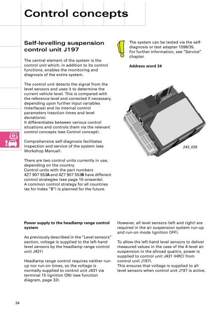
control unit J197<br />
The central element of the <strong>system</strong> is the<br />
control unit which, in addition to its control<br />
functions, enables the monitoring and<br />
diagnosis of the entire <strong>system</strong>.<br />
The <strong>system</strong> can be tested via the selfdiagnosis<br />
or test adapter 1598/35.<br />
For further information, see “Service”<br />
chapter.<br />
Address word 34<br />
The control unit detects the signal from the<br />
<strong>level</strong> sensors and uses it to determine the<br />
current vehicle <strong>level</strong>. This is compared with<br />
the reference <strong>level</strong> and corrected if necessary,<br />
depending upon further input variables<br />
(interfaces) and its internal control<br />
parameters (reaction times and <strong>level</strong><br />
deviations).<br />
It differentiates between various control<br />
situations and controls them via the relevant<br />
control concepts (see Control concept).<br />
Comprehensive self-diagnosis facilitates<br />
inspection and service of the <strong>system</strong> (see<br />
Workshop Manual).<br />
243_039<br />
There are two control units currently in use,<br />
depending on the country.<br />
Control units with the part numbers<br />
4Z7 907 553A and 4Z7 907 553B have different<br />
control strategies (see page 10 onwards).<br />
A common control strategy for all countries<br />
(as for Index “B”) is planned for the future.<br />
Power supply to the headlamp range control<br />
<strong>system</strong><br />
As previously described in the “Level sensors”<br />
section, voltage is supplied to the left-hand<br />
<strong>level</strong> sensors by the headlamp range control<br />
unit J431)<br />
Headlamp range control requires neither runup<br />
nor run-on times, so the voltage is<br />
normally supplied to control unit J431 via<br />
terminal 15 (ignition ON) (see function<br />
diagram, page 32).<br />
However, all <strong>level</strong> sensors (left and right) are<br />
required in the <strong>air</strong> <strong>suspension</strong> <strong>system</strong> run-up<br />
and run-on mode (ignition OFF).<br />
To allow the left-hand <strong>level</strong> sensors to deliver<br />
measured values in the case of the 4-<strong>level</strong> <strong>air</strong><br />
<strong>suspension</strong> in the allroad quattro, power is<br />
supplied to control unit J431 (HRC) from<br />
control unit J197).<br />
This ensures that voltage is supplied to all<br />
<strong>level</strong> sensors when control unit J197 is active.<br />
34


