Plena System Pre-amplifier and Call Stations - WES Components
Plena System Pre-amplifier and Call Stations - WES Components
Plena System Pre-amplifier and Call Stations - WES Components

You also want an ePaper? Increase the reach of your titles
YUMPU automatically turns print PDFs into web optimized ePapers that Google loves.
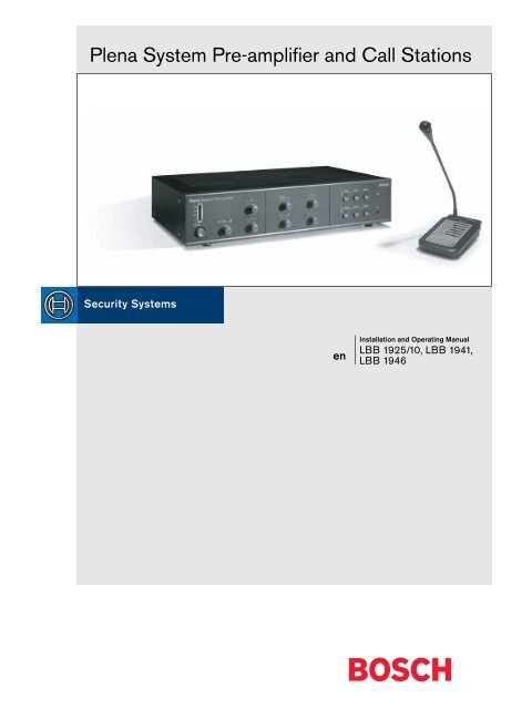
<strong>Plena</strong> <strong>System</strong> <strong>Pre</strong>-<strong>amplifier</strong> <strong>and</strong> <strong>Call</strong> <strong>Stations</strong><br />
en<br />
Installation <strong>and</strong> Operating Manual<br />
LBB 1925/10, LBB 1941,<br />
LBB 1946
<strong>Plena</strong> <strong>System</strong> <strong>Pre</strong>-<strong>amplifier</strong> | Installation <strong>and</strong> Operating Manual | Important safeguards en | 3<br />
Important safeguards<br />
1 Read instructions - All the safety instructions for use<br />
should be read before the system is operated.<br />
2 Retain instructions - The safety instructions <strong>and</strong><br />
instructions for use should be retained for future<br />
reference.<br />
3 Heed warnings - All warnings on the unit <strong>and</strong> in the<br />
operating instructions should be adhered to.<br />
4 Follow instructions - All operating instructions <strong>and</strong><br />
instructions for use should be followed.<br />
5 Cleaning - Unplug system units from the mains outlet<br />
before cleaning. Do not use liquid cleaners or aerosol<br />
cleaners. Use a damp cloth for cleaning.<br />
6 Attachments - Do not use attachments not<br />
recommended by the product manufacturer as they may<br />
cause hazards.<br />
7 Water <strong>and</strong> Moisture - Do not use this unit near water, for<br />
example near a bathtub, washbowl, kitchen sink, or<br />
laundry basket, in a wet basement, near a swimming<br />
pool, in an unprotected outdoor installation or any area<br />
which is classified as a wet location.<br />
8 Accessories - Do not place this unit on an unstable st<strong>and</strong>,<br />
tripod, bracket or mount. This unit may fall, causing<br />
serious injury to a person <strong>and</strong> serious damage to the<br />
unit. Use only a st<strong>and</strong>, tripod, bracket or mount<br />
recommended by the manufacturer, or sold with the<br />
product. Any mounting of the unit should follow the<br />
manufacturer's instructions, <strong>and</strong> should use a mounting<br />
accessory recommended by the manufacturer. An<br />
appliance <strong>and</strong> cart combination should be moved with<br />
care. Quick stops, excessive force, <strong>and</strong> uneven surfaces<br />
may cause the appliance <strong>and</strong> cart combination to<br />
overturn.<br />
9 Ventilation - Openings in the enclosure, if any, are<br />
provided for ventilation <strong>and</strong> to ensure reliable operation<br />
of the unit <strong>and</strong> to protect it from overheating. These<br />
openings must not be blocked or covered. The unit<br />
should not be placed in a built-in installation unless<br />
proper ventilation is provided or the manufacturer's<br />
instructions have been adhered to.<br />
10 Power sources - Units should be operated only from the<br />
type of power source indicated on the marking label. If<br />
you are not sure of the type of power supply you plan to<br />
use, consult your appliance dealer or local power<br />
company. For units intended to operate from battery<br />
power, or other sources, refer to the "Installation <strong>and</strong><br />
User Instructions".<br />
11 Grounding or polarisation - This unit may be equipped<br />
with a polarised alternating current line plug (a plug<br />
having one blade wider than the other). This plug will fit<br />
into the power outlet only one way. This is a safety<br />
feature. If you are unable to insert the plug fully into the<br />
outlet, try reversing the plug. If the plug still fails to fit,<br />
contact your electrician to replace your obsolete outlet.<br />
Do not defeat the safety purpose of the polarised plug.<br />
Alternatively, this unit may be equipped with a 3-wire<br />
grounding type plug having a third (grounding) pin.<br />
This plug will only fit into a grounding-type power<br />
outlet. This is a safety feature. If you are unable to insert<br />
the plug into the outlet, contact your electrician to<br />
replace your obsolete outlet. Do not defeat the safety<br />
purpose of the grounding-type lug.<br />
12 Power-Cord Protection - Power supply cords should be<br />
routed so that they are not likely to be walked on or<br />
pinched by items placed upon or against them, paying<br />
particular attention to cords <strong>and</strong> plugs, convenience<br />
receptacles, <strong>and</strong> the point where they exit from the<br />
appliance.<br />
13 Overloading - Do not overload outlets <strong>and</strong> extension<br />
cords as this can result in a risk of fire or electrical shock.<br />
14 Object <strong>and</strong> Liquid Entry - Never push objects of any<br />
kind into this unit through openings as they may touch<br />
dangerous voltage points or short-out parts that could<br />
result in a fire or electric shock. Never spill liquid of any<br />
kind on the unit.<br />
15 Servicing - Do not attempt to service this unit yourself as<br />
opening or removing covers may expose to dangerous<br />
voltage or other hazards. Refer all servicing to qualified<br />
service personnel.<br />
16 Damage Requiring Service - Unplug the unit from the<br />
outlet <strong>and</strong> refer servicing to qualified service personnel<br />
under the following conditions:<br />
• When the power-supply cord or plug is damaged.<br />
• If liquid has been spilled, or objects have fallen into<br />
the unit.<br />
• If the unit has been exposed to rain or water.<br />
• If the unit does not operate normally by following<br />
the instructions for use. Adjust only those controls<br />
that are covered by the instructions for use, as an<br />
improper adjustment of other controls may result in<br />
damage <strong>and</strong> will often require extensive work by a<br />
qualified technician to restore the units to their<br />
normal operation.<br />
• If the unit has been dropped or the unit has been<br />
damaged.<br />
• When the unit exhibits a distinct change in<br />
performance; this indicates a need for service.<br />
17 Replacement Parts - When replacement parts are<br />
required be sure the service technician has used<br />
replacement parts specified by the manufacturer or parts<br />
which have the same characteristics as the original part.<br />
Unauthorised substitutions may result in fire, electric<br />
shock or other hazards.<br />
18 Safety Check - Upon completion of any service or<br />
repairs to the units, ask the service technician to perform<br />
safety checks to determine that the unit is in proper<br />
operating condition.<br />
19 Lightning - For added protection of the units during a<br />
lightning storm, or when it is left unattended <strong>and</strong> unused<br />
for long periods of time, unplug it from the wall outlet<br />
<strong>and</strong> disconnect the cable system. This will prevent<br />
damage to the unit due to lightning <strong>and</strong> power-line<br />
surges.<br />
Bosch Security <strong>System</strong>s | 2003-09 | 3922 988 99483en
<strong>Plena</strong> <strong>System</strong> <strong>Pre</strong>-<strong>amplifier</strong> | Installation <strong>and</strong> Operating Manual | About this manual en | 4<br />
About this manual<br />
This manual provides all the information required to install <strong>and</strong> operate the unit.<br />
Conventions<br />
Warning<br />
Follow these instructions to prevent personal injury.<br />
Caution<br />
Follow these instructions to prevent damage to the equipment.<br />
Note<br />
Read these instructions for tips <strong>and</strong> other useful information.<br />
Safety precautions<br />
Warning<br />
Do not open the unit when it is connected to the mains. The unit contains non-insulated parts, which can<br />
cause electric shock.<br />
Caution<br />
There are no user-serviceable parts inside the unit. Service must be done by qualified personnel.<br />
Bosch Security <strong>System</strong>s | 2003-09 | 3922 988 99483en
<strong>Plena</strong> <strong>System</strong> <strong>Pre</strong>-<strong>amplifier</strong> | Installation <strong>and</strong> Operating Manual | Table of contents en | 5<br />
Table of contents<br />
Important safeguards..........................................................................................................................................................3<br />
About this manual ..............................................................................................................................................................4<br />
Safety precautions...............................................................................................................................................................4<br />
Table of contents ................................................................................................................................................................5<br />
1 About the system pre-<strong>amplifier</strong> .......................................................................................................................................7<br />
1.1 Controls & Connections (front) ...............................................................................................................................8<br />
1.2 Controls & connections (rear) ..................................................................................................................................8<br />
2 Internal settings (system pre-<strong>amplifier</strong>) ...........................................................................................................................9<br />
2.1 Setting the zones for trigger 1 <strong>and</strong> 2 .......................................................................................................................9<br />
2.2 Setting tones ..............................................................................................................................................................9<br />
2.3 Setting the Speech filter <strong>and</strong> call station volume ................................................................................................10<br />
2.4 Setting priority .........................................................................................................................................................10<br />
2.5 Setting single <strong>and</strong> dual channel use ......................................................................................................................11<br />
2.6 Override contact setting .........................................................................................................................................11<br />
3 Installation in rack (system pre-<strong>amplifier</strong>) ....................................................................................................................12<br />
4 External settings <strong>and</strong> connections (system pre-<strong>amplifier</strong>) ...........................................................................................13<br />
4.1 Connect the DC supply (battery) ..........................................................................................................................13<br />
4.2 Connect a microphone ...........................................................................................................................................14<br />
4.3 Connect the call stations ........................................................................................................................................15<br />
4.4 Connect an emergency input line .........................................................................................................................15<br />
4.5 Connect audio sources for background music .....................................................................................................16<br />
4.6 Connect to a booster ..............................................................................................................................................17<br />
5 Operation (system pre-<strong>amplifier</strong>) ...................................................................................................................................18<br />
6 About the call stations .....................................................................................................................................................19<br />
6.1 Controls & Connections (top) ................................................................................................................................20<br />
7 Internal settings (call stations) ........................................................................................................................................21<br />
7.1 Chime .......................................................................................................................................................................21<br />
7.2 Setting sensitivity & speech filter ...........................................................................................................................21<br />
8 Operation (call stations) ..................................................................................................................................................22<br />
9 Technical data ..................................................................................................................................................................23<br />
9.1 <strong>System</strong> pre-<strong>amplifier</strong> LBB 1925 ............................................................................................................................23<br />
9.1.1 Electrical .............................................................................................................................................................23<br />
9.1.2 Performance .......................................................................................................................................................23<br />
9.1.3 Inputs ..................................................................................................................................................................23<br />
9.1.4 Outputs ...............................................................................................................................................................24<br />
9.1.5 Relays ..................................................................................................................................................................24<br />
9.1.6 Environmental conditions .................................................................................................................................24<br />
9.1.7 General ...............................................................................................................................................................24<br />
9.2 All-call call station LBB 1941 ................................................................................................................................25<br />
9.2.1 Electrical .............................................................................................................................................................25<br />
9.2.2 Performance .......................................................................................................................................................25<br />
9.2.3 Environmental conditions .................................................................................................................................25<br />
9.2.4 General ...............................................................................................................................................................25<br />
9.3 6-zone call station LBB 1946 .................................................................................................................................26<br />
9.3.1 Electrical .............................................................................................................................................................26<br />
9.3.2 Performance .......................................................................................................................................................26<br />
Bosch Security <strong>System</strong>s | 2003-09 | 3922 988 92483en
<strong>Plena</strong> <strong>System</strong> <strong>Pre</strong>-<strong>amplifier</strong> | Installation <strong>and</strong> Operating Manual | Table of contents en | 6<br />
9.3.3 Selections ............................................................................................................................................................26<br />
9.3.4 Environmental conditions .................................................................................................................................26<br />
9.3.5 General ...............................................................................................................................................................26<br />
Chime tone tables.............................................................................................................................................................27<br />
Bosch Security <strong>System</strong>s | 2003-09 | 3922 988 92483en
-6 dB<br />
-20 dB<br />
Power<br />
CD AUX<br />
<strong>Plena</strong> <strong>System</strong> <strong>Pre</strong>-<strong>amplifier</strong> | Installation <strong>and</strong> Operating Manual | About the system pre-<strong>amplifier</strong><br />
en | 7<br />
1 About the system pre-<strong>amplifier</strong><br />
<strong>Plena</strong> <strong>System</strong> <strong>Pre</strong>-<strong>amplifier</strong><br />
0 dB<br />
/Line<br />
Select Z1 Z2 Z3<br />
+<br />
+<br />
Z4 Z5 Z6<br />
Figure 1.1<br />
Block Diagram LBB 1925/10<br />
Tone<br />
B1<br />
Tone 1<br />
B2 Chime<br />
01<br />
2<br />
<strong>Call</strong> 100V<br />
<strong>Call</strong> 0V<br />
J2<br />
CAll & BGM 0V<br />
Zone 1,0V Out<br />
Alarm/Timer<br />
Tel/EMG<br />
Trigger 1<br />
Trigger 2<br />
VOX<br />
<strong>Call</strong> Station In Use<br />
M.C.U.<br />
S301<br />
1 2 3 4 5 6 7 8<br />
Alarm/Timer/Chime<br />
Tone<br />
LBB1941/00<br />
S302<br />
S303<br />
Z1<br />
Z2<br />
1 2<br />
Tone<br />
Z1<br />
Z2<br />
Z3<br />
3<br />
Z3<br />
Z4<br />
4<br />
Z4<br />
Z5 Z6<br />
5<br />
Z5<br />
6<br />
Z6<br />
A1<br />
7<br />
A2<br />
8<br />
3 1 2 4 5 7 6 8<br />
Tigger 1<br />
Tigger 2<br />
Alarm/Timer<br />
BGM 100V<br />
BGM 0V<br />
<strong>Call</strong> active<br />
R1<br />
RA1<br />
Front panel<br />
Key switch<br />
Zone 1<br />
CAll & BGM 0V<br />
24V DC<br />
J4<br />
RB1<br />
Zone 1,100V Out<br />
Zone 1 override<br />
Zone 2,0V Out<br />
VR1<br />
Zone 2,100V Out<br />
P.S.<br />
Priority<br />
RA2<br />
/Line<br />
S101<br />
1mV<br />
200mV<br />
Speech filter<br />
JP101<br />
ON/OFF<br />
Out<br />
Announcement<br />
Tone Control<br />
VU LED<br />
Master out<br />
Front panel<br />
Key switch<br />
Zone 2<br />
CAll & BGM 0V<br />
RB2<br />
Zone 2 override<br />
Zone 3,0V Out<br />
Zone 3,100V Out<br />
CD<br />
O<br />
Selector<br />
Music<br />
Tone Control<br />
JP102<br />
1-CH use<br />
2-CH use<br />
Headphone<br />
RA3<br />
Front panel<br />
Key switch<br />
Zone 3<br />
RB3<br />
Zone 3 override<br />
Aux<br />
Zone 4,0V Out<br />
PC Audio In<br />
Interface<br />
VR101<br />
O<br />
CAll & BGM 0V<br />
Zone 4,100V Out<br />
RA4<br />
Front panel<br />
Key switch<br />
Zone 4 override<br />
RS-485<br />
Zone 4<br />
RB4<br />
RS-232<br />
CAll & BGM 0V<br />
Zone 5,0V Out<br />
F1<br />
115V/230V<br />
F101<br />
F102<br />
24V DC<br />
+<br />
24V DC OUT<br />
RA5<br />
Zone 5,100V Out<br />
0.5A<br />
0.5A 0.5A<br />
-<br />
Front panel<br />
Key switch<br />
Zone 5 override<br />
18V DC<br />
Zone 5<br />
RB5<br />
24V DC IN<br />
+<br />
-<br />
F101<br />
1.5A<br />
CAll & BGM 0V<br />
Zone 6,0V Out<br />
Zone 6,100V Out<br />
RA6<br />
Front panel<br />
Key switch<br />
Zone 6 override<br />
Zone 6<br />
RB6<br />
Figure 1.2<br />
The <strong>Plena</strong> <strong>System</strong> <strong>Pre</strong>-<strong>amplifier</strong> is a mono <strong>amplifier</strong>, which mixes a call-station signal with a background music<br />
signal. You can adjust the volume <strong>and</strong> tone for both signals. The background music channel has 3 possible inputs<br />
(CD, Tape <strong>and</strong> AUX) <strong>and</strong> a direct XLR output for 2-channel use. Internal relays control the audio routing to the<br />
6 zones. The zone selection keys at the front determine to which zones the background music is send.<br />
Bosch Security <strong>System</strong>s | 2003-09 | 3922 988 99483en
<strong>Plena</strong> <strong>System</strong> <strong>Pre</strong>-<strong>amplifier</strong> | Installation <strong>and</strong> Operating Manual | About the system pre-<strong>amplifier</strong><br />
en | 8<br />
1.1 Controls & Connections (front)<br />
1<br />
2<br />
<strong>Plena</strong> <strong>System</strong> <strong>Pre</strong>-<strong>amplifier</strong><br />
0dB<br />
-6 dB<br />
-20 dB<br />
Select<br />
CD<br />
AUX<br />
Z1 Z2 Z3<br />
11<br />
Power<br />
/Line<br />
Z4 Z5 Z6<br />
3<br />
0 0<br />
Figure 1.3<br />
4 5 6 7 8 9 10<br />
1 VU meter (LED bar)<br />
2 Power on indication LED (green)<br />
3 Power on/off<br />
4 Volume control, mic/line<br />
5 Tone control, mic/line<br />
6 Volume control, background music<br />
7 Background music selection switch<br />
8 Tone control, background music<br />
9 Zone selection keys, background music<br />
10 Headphone connection<br />
11 Indication LED, call station active<br />
1.2 Controls & connections (rear)<br />
11<br />
12 13 14<br />
15<br />
16 7 17 18 19 20<br />
Tel/EMG<br />
Trigger 1 Trigger 2<br />
LBB1925/10<br />
890019251005<br />
115/230V~,50/60Hz<br />
No.<br />
Apparatus delivered 115V<br />
connected for 230V-<br />
230V<br />
/Line<br />
1-<br />
3 1 3<br />
5 4<br />
4 5 2<br />
0<br />
1. Audio+<br />
2.0V<br />
3.Audio-<br />
4.24Vd.c.<br />
/Line<br />
5. Allcall<br />
6.Data-<br />
7.Data+<br />
8.Chs.GND<br />
7 6<br />
3 8<br />
5 4<br />
2<br />
PCAudoln<br />
L<br />
R<br />
1<br />
RS232 CD Aux<br />
+ GND GND +<br />
2 - 1 1 - 2<br />
3<br />
3<br />
MasterOut<br />
Out<br />
100V 0<br />
100V 0<br />
100V 0 100V 0 100V 0 100V 0<br />
100V 0 100V 0<br />
+24V- +24V-<br />
Warning<br />
This apparatus must be earthed<br />
Rated Input<br />
Power : 50VA<br />
T0.5L 250V<br />
21<br />
22<br />
1<br />
2 3 4 5 6 7 8 9 10<br />
Figure 1.4<br />
1 Mic/line input (DIN)<br />
2 Mic/line input (XLR)<br />
3 <strong>Call</strong> station input (8-pin DIN)<br />
4 Audio input from PC (Cinch)<br />
5 Master output (XLR)<br />
6 Background music output (XLR)<br />
7 100V LSP output (zone 1 to 6)<br />
8 24V DC output for relays (terminal)<br />
9 24V DC input (terminal)<br />
10 Earth connection screw<br />
11 Volume control (Tel/Emergency input)<br />
12 Telephone/Emergency signal input<br />
13 Alarm/time signal, trigger inputs<br />
14 Control input for PC (RS232; 9-pin)<br />
15 CD/ Tape/Auxiliary input (Cinch)<br />
16 Tape output (Cinch)<br />
17 <strong>Call</strong> active control output (terminal)<br />
18 <strong>Call</strong> input from booster (terminal)<br />
19 Music input from booster (terminal)<br />
20 Mains voltage switch (115/230V)<br />
21 Mains socket<br />
22 Mains fuse<br />
Bosch Security <strong>System</strong>s | 2003-09 | 3922 988 99483en
<strong>Plena</strong> <strong>System</strong> <strong>Pre</strong>-<strong>amplifier</strong> | Installation <strong>and</strong> Operating Manual | Internal settings<br />
en | 9<br />
2 Internal settings (system pre-<strong>amplifier</strong>)<br />
1925-8<br />
CN104<br />
S301<br />
CN103<br />
B1 B2 1 1941<br />
ZONE 1 2 3 4 5 6 A1 ZONE 1 2 3 4 5 6 A2<br />
1 8 1 8 1 8<br />
ON ON ON<br />
S302<br />
S303<br />
CHIMEVOL.<br />
VR1<br />
CN101<br />
CND001<br />
CND003<br />
CND002<br />
CN105<br />
CND102<br />
Figure 2.1<br />
2.1 Setting the zones for trigger 1 <strong>and</strong> 2<br />
Trigger inputs 1 <strong>and</strong> 2 on the rear panel may start alarm or time signals upon closing its contact. The zones for<br />
trigger 1 can be set with S302 (bit 1 to 6), for trigger 2 with S303 (bit 1 to 6). The selected zones receive a time or<br />
alarm tone when the trigger is activated. Time tones are edge triggered <strong>and</strong> last the duration of the chime. Alarm<br />
tones are level triggered <strong>and</strong> last until released.<br />
2.2 Setting tones<br />
The time or alarm tone for trigger 1 can be set with S301 (bit 1 <strong>and</strong> 2) <strong>and</strong> S302 (bit 7 <strong>and</strong> 8), for trigger 2 with S301<br />
(bit 3 <strong>and</strong> 4) <strong>and</strong> S303 (bit 7 <strong>and</strong> 8). If you use a LBB 1941 call station, the chime tone must be set with S301 (bit 6<br />
to 8). You can find the chime tone tables at the end of the manual. With S301 (bit 5) the 2-tone chime on the DIN<br />
priority contact for mic/line can be enabled or disabled. The 2-tone chime is 554 Hz (1s), 440 Hz (1s). You can set<br />
the chime volume with VR1.<br />
Bosch Security <strong>System</strong>s | 2003-09 | 3922 988 99483en
<strong>Plena</strong> <strong>System</strong> <strong>Pre</strong>-<strong>amplifier</strong> | Installation <strong>and</strong> Operating Manual | Internal settings<br />
en | 10<br />
2.3 Setting the Speech filter <strong>and</strong> call station volume<br />
MUSIC OUT<br />
MASTER OUT<br />
PC AUDIO<br />
IN<br />
CALL STATIONS<br />
SWITCH<br />
LINE<br />
XLR<br />
DIN<br />
CN21<br />
CN24<br />
U106<br />
VR101<br />
CALL STATION<br />
LEVEL<br />
JP101<br />
OFF ON<br />
CN4<br />
J2<br />
25-1<br />
C179<br />
1 CH USE<br />
2<br />
CH USE<br />
CN9<br />
RL701 R701<br />
D701<br />
CN17<br />
CN107<br />
CN6<br />
CN1<br />
CN14<br />
Q701<br />
CN10<br />
CN23<br />
25-7<br />
3938 101 90282<br />
CN8<br />
CN18<br />
JP102<br />
1CHUSE 2CHUSE<br />
CN13<br />
Figure 2.2 Figure 2.3<br />
The Speech filter for the mic/line input can be switched on/off with jumper JP101 (default ON).<br />
You can set the call station volume with VR101.<br />
2.4 Setting priority<br />
The priority cannot be set manually. The default priority order is:<br />
1 Emergency/Telephone input<br />
2 Trigger 1 or 2 (first comes, first served)<br />
3 All-call call station LBB 1941<br />
4 6-zone call station LBB 1946 (DIP switch setting of LBB 1946)<br />
5 6-zone call station LBB 1946 (DIP switch setting of LBB 1946)<br />
6 Background music <strong>and</strong> mic/line input<br />
Bosch Security <strong>System</strong>s | 2003-09 | 3922 988 99483en
<strong>Plena</strong> <strong>System</strong> <strong>Pre</strong>-<strong>amplifier</strong> | Installation <strong>and</strong> Operating Manual | Internal settings<br />
en | 11<br />
2.5 Setting single <strong>and</strong> dual channel use<br />
The system pre-<strong>amplifier</strong> can be used with one booster <strong>amplifier</strong> for both music <strong>and</strong> calls ('1 channel use'). Any call<br />
will interrupt background music in all zones. It is also possible to use separate booster <strong>amplifier</strong>s, for music <strong>and</strong> calls<br />
('2 channel use'). Now a call will not interrupt music in zones, not addressed by the call. Jumper JP102 selects<br />
whether background music is going to the Master output (1 channel use) or not (2 channel use). Jumper J2 must be<br />
set to either 1 channel use or 2 channel use to select the <strong>amplifier</strong> terminals for the zones.<br />
2.6 Override contact setting<br />
3-wire (zone 1-6)<br />
0V<br />
D614 RL606 D613 RL605 RL604 RL603 RL602 RL601<br />
AMPLIFIER<br />
100V<br />
CN24<br />
OVERRIDE<br />
LOCAL VOLUME<br />
CONTROL<br />
CN21<br />
J4<br />
Override<br />
24V dc<br />
100V<br />
audio<br />
CN3<br />
D606 D605<br />
D604 D603<br />
RL612<br />
RL611<br />
RL610<br />
RL609<br />
D602<br />
RL608<br />
D601<br />
RL607<br />
CN22 CN20<br />
Figure 2.5<br />
4-wire (zone 1-6)<br />
AMPLIFIER<br />
0V<br />
100V<br />
LOCAL VOLUME CONTROL<br />
RL612 RL611<br />
RL610 RL609<br />
RL608<br />
RL607<br />
24V<br />
OVERRIDE<br />
J3<br />
25-6 3938 101 90272<br />
DC Out 24V (-)<br />
Figure 2.4 Figure 2.6<br />
Jumpers J3 <strong>and</strong> J4 select whether the override output for each zone (indicated by ) is switching between the 0V<br />
<strong>and</strong> 100V loudspeaker signal, or between ground <strong>and</strong> 24Vdc. This override output is available per zone <strong>and</strong> may be<br />
used to override local volume controls, to make sure that calls are coming through. For 3-wire volume override, the<br />
jumpers should be in 100V audio position. For 4-wire override the jumpers should be in 24Vdc position. The<br />
drawings show the principle of 3- <strong>and</strong> 4-wire volume override. The override outputs are activated whenever a call is<br />
made, when the emergency input is activated, or an alarm or time signal is triggered. At the same time also the <strong>Call</strong><br />
Active relay is activated, providing a potential free contact.<br />
Bosch Security <strong>System</strong>s | 2003-09 | 3922 988 99483en
-20 dB<br />
CD AUX<br />
<strong>Plena</strong> <strong>System</strong> <strong>Pre</strong>-<strong>amplifier</strong> | Installation <strong>and</strong> Operating Manual | Installation in rack<br />
en | 12<br />
3 Installation in rack (system pre-<strong>amplifier</strong>)<br />
<strong>Plena</strong> <strong>System</strong> <strong>Pre</strong>-<strong>amplifier</strong><br />
0 dB<br />
-6 dB<br />
Power<br />
/Line<br />
Select Z1 Z2 Z3<br />
+<br />
+<br />
Z4 Z5 Z6<br />
Figure 3.1<br />
The system pre-<strong>amplifier</strong> is delivered for tabletop use, but you can mount it in a 19" rack.<br />
If you mount the pre-<strong>amplifier</strong> in a rack, you must:<br />
• use the mounting brackets delivered with the unit.<br />
• remove the 4 feet from the bottom of the unit. (Without the feet the unit is 2U high.)<br />
Bosch Security <strong>System</strong>s | 2003-09 | 3922 988 99483en
00V 0 100V 0<br />
+24V- +24V-<br />
Warning<br />
115V- 23<br />
/Line<br />
1-<br />
3 1<br />
5 4<br />
2<br />
Tel/EMG<br />
0<br />
/Line<br />
Tri ger 2<br />
5.A lca l<br />
6.Data-<br />
7 6<br />
3 8 1<br />
5 4<br />
2<br />
L<br />
RS232<br />
R<br />
MasterOut<br />
CD<br />
Out<br />
+ -<br />
GND<br />
2 1<br />
3<br />
Aux<br />
+<br />
-<br />
GND<br />
1 2<br />
3<br />
Zone 1<br />
Zone 5<br />
Zone 6<br />
In<br />
+24V- +24V-<br />
Warning<br />
This a paratus must be earthed<br />
T1.0AL 250V<br />
<strong>Plena</strong> <strong>System</strong> <strong>Pre</strong>-<strong>amplifier</strong> | Installation <strong>and</strong> Operating Manual | External settings <strong>and</strong> connections en | 13<br />
4 External settings <strong>and</strong> connections (system pre-<strong>amplifier</strong>)<br />
4.1 Connect the DC supply (battery)<br />
6<br />
<strong>Call</strong> Active <strong>Call</strong> In<br />
Apparatus delivered<br />
connected for230V-<br />
In<br />
100V 0 100V 0<br />
Zone 3 Zone 4 DC Out DC In<br />
4<br />
3<br />
5<br />
Tri ger 1<br />
1.Audio+<br />
2.0V<br />
3.Audio-<br />
7.Data+<br />
4.24Vd.c. 8.Chs.GND<br />
LBB1925/00<br />
890019250005<br />
15/230V~,50/60Hz<br />
No.<br />
PCAudioIn<br />
Ca l Active Ca l In<br />
100V 0 100V 0 100V 0 100V 0<br />
Apparatus delivered<br />
connected for 230V- 115V- 230V-<br />
0V 0<br />
Zone 2 Zone 3 Zone 4 DC Out DC In<br />
100V 0 100V 0 100V 0 100V 0<br />
100V 0<br />
Rated input<br />
Power : 50VA<br />
+ -<br />
This apparatus must be earthed<br />
-<br />
F<br />
12 VDC 12 VDC<br />
+<br />
F=1.5A<br />
Figure 4.1<br />
The system pre-<strong>amplifier</strong> has a 24 Vdc input (terminal screw), which you can use to connect a back up power<br />
supply, e.g. batteries. You can earth the unit to increase the electrical stability of the system.<br />
Caution<br />
The connection cable must have an in-line fuse. Use the type of fuse as mentioned in the illustration.<br />
Bosch Security <strong>System</strong>s | 2003-09 | 3922 988 99483en
3<br />
2<br />
1<br />
3<br />
8<br />
2<br />
1<br />
MasterOut<br />
+ -<br />
GND<br />
/Line<br />
1-<br />
3 1<br />
5 4<br />
2<br />
Tel/EMG<br />
0<br />
/Line<br />
Tri ger 2<br />
7 6<br />
3 8 1<br />
5 4<br />
2<br />
L<br />
RS232<br />
R<br />
CD<br />
Out<br />
+ -<br />
GND<br />
2 1<br />
3<br />
Aux<br />
+<br />
-<br />
GND<br />
1 2<br />
3<br />
Zone 1<br />
Zone 5<br />
100V<br />
In<br />
Warning<br />
T1.0AL 250V<br />
<strong>Plena</strong> <strong>System</strong> <strong>Pre</strong>-<strong>amplifier</strong> | Installation <strong>and</strong> Operating Manual | External settings <strong>and</strong> connections en | 14<br />
4.2 Connect a microphone<br />
Tel/EMG<br />
Trigger 1<br />
/Line<br />
/Line<br />
1- 3<br />
4 5<br />
5 4<br />
0<br />
Trigger 2<br />
5.A lca l<br />
6.Data-<br />
1.Audio+<br />
2.0V<br />
3.Audio-<br />
4.24Vd.c.<br />
5.Allcall<br />
6.Data-<br />
7.Data+<br />
8.Chs.GND<br />
LBB1925/00<br />
890019250005<br />
115/230V~,50/60Hz<br />
No.<br />
PCAudioIn<br />
L<br />
RS232<br />
CD<br />
4<br />
3<br />
5<br />
Tri ger 1<br />
1.Audio+<br />
2.0V<br />
3.Audio-<br />
7.Data+<br />
4.24Vd.c. 8.Chs.GND<br />
LBB1925/00<br />
890019250005<br />
15/230V~,50/60Hz<br />
No.<br />
PCAudioIn<br />
MasterOut<br />
Zone 6 Ca l Active Ca l In<br />
100V 0 100V 0<br />
100V 0 0<br />
Zone 2 Zone 1 Zone 2 DC Out DC In<br />
100V 0 100V 0 100V 0 100V 0<br />
+24V- +24V-<br />
Apparatus delivired<br />
connected for 230V- 115V- 230V-<br />
This a paratus must be earthed<br />
Rated input<br />
Power : 50VA<br />
7 6<br />
5 4<br />
R<br />
2 1<br />
3<br />
- GND<br />
3<br />
1<br />
Out<br />
GND<br />
GND<br />
180 5-pole DIN 180 3-pole XLR<br />
Figure 4.2<br />
The input channel has 2 possible balanced inputs, use one of these inputs to connect a microphone or a line-level<br />
source. If you use an input make sure that the 'mic/line' switch is in the correct position.<br />
Note<br />
If you want to use the priority feature, you must use a microphone or line-level source with a priority contact<br />
on pin 4 <strong>and</strong> 5 of the 5-pole DIN plug.<br />
Bosch Security <strong>System</strong>s | 2003-09 | 3922 988 99483en
3 1<br />
5 4<br />
2<br />
3<br />
2<br />
1<br />
7 6<br />
3 8 1<br />
5 4<br />
2<br />
3<br />
MasterOut<br />
2<br />
1<br />
MasterOut<br />
/Line<br />
1-<br />
3 1<br />
5 4<br />
2<br />
Tel/EMG<br />
0<br />
+ -<br />
GND<br />
3<br />
Tri ger 2<br />
1.Audio+ 5.A lca l<br />
2.0V 6.Data-<br />
3.Audio- 7.Data+<br />
4.24Vd.c. 8.Chs.GND<br />
/Line<br />
PCAudioIn<br />
7 6<br />
3 8 1<br />
5 4<br />
2<br />
/Line<br />
1-<br />
3 1<br />
5 4<br />
2<br />
L<br />
RS232<br />
R<br />
MasterOut<br />
Tel/EMG<br />
0<br />
CD<br />
Out<br />
+ -<br />
GND<br />
2 1<br />
3<br />
Tri ger 2<br />
Aux<br />
+<br />
-<br />
GND<br />
1 2<br />
3<br />
1.Audio+ 5.A lca l<br />
2.0V 6.Data-<br />
3.Audio- 7.Data+<br />
4.24Vd.c.<br />
/Line<br />
PCAudioIn<br />
7 6<br />
3 8 1<br />
5 4<br />
2<br />
Zone 1<br />
L<br />
RS232<br />
R<br />
Zone 5<br />
1 0V<br />
MasterOut<br />
CD<br />
Out<br />
+ -<br />
GND<br />
2 1<br />
3<br />
Aux<br />
+<br />
-<br />
GND<br />
1 2<br />
3<br />
In<br />
Warning<br />
15V- 230V-<br />
Rated input<br />
Power : 50VA<br />
T1.0AL 250V<br />
Zone 5<br />
1 0V<br />
Zone 1<br />
In<br />
1 0V 0 0<br />
+24V- +24V-<br />
Warning<br />
15V- 230V-<br />
Rated input<br />
Power : 50VA<br />
T1.0AL 250V<br />
<strong>Plena</strong> <strong>System</strong> <strong>Pre</strong>-<strong>amplifier</strong> | Installation <strong>and</strong> Operating Manual | External settings <strong>and</strong> connections en | 15<br />
4.3 Connect the call stations<br />
Tel/EMG<br />
0<br />
Trigger 1<br />
/Line<br />
/Line<br />
1- 3<br />
4 5<br />
Trigger 2<br />
5.A lca l<br />
6.Data-<br />
7.Data+<br />
4.24Vd.c. 8.Chs.GND<br />
1.Audio+<br />
2.0V<br />
3.Audio-<br />
LBB1925/00<br />
890019250005<br />
115/230V~,50/60Hz<br />
No.<br />
PCAudioIn<br />
L<br />
RS232<br />
CD<br />
4<br />
35<br />
Tri ger 1<br />
L B1925/ 0<br />
89 01925 05<br />
15/230V~,50/60Hz<br />
No.<br />
Zone 6 Ca l Active Ca l In<br />
1 0V 0 1 0V 0 1 0V 0 1 0V 0<br />
Zone 2 Zone 3 Zone 4 DC Out DC In<br />
1 0V 0 0 1 0V 0 1 0V 0 +24V- +24V-<br />
A paratus delivired<br />
co nected for 230V-<br />
This a paratus must b earthed<br />
R<br />
2 1<br />
Out<br />
A<br />
B<br />
B<br />
A<br />
Figure 4.3<br />
You can connect 2 <strong>Plena</strong> <strong>Call</strong> <strong>Stations</strong> directly to the system pre-<strong>amplifier</strong>. To connect up to the maximum of 8 call<br />
stations you must use a loop through connection. The loop through can contain both types of call stations.<br />
4.4 Connect an emergency input line<br />
4<br />
35<br />
Tri ger 1<br />
8.Chs.GND<br />
LBB1925/ 0<br />
89 01925 05<br />
15/230V~,50/60Hz<br />
No.<br />
Zone 6 Ca l Active Ca l In<br />
1 0V 0 0 1 0V<br />
A paratus delivired<br />
co nected for 230V-<br />
Zone 2 Zone 1 Zone 2 DC Out DC In<br />
1 0V 0 1 0V 0 1 0V 0 1 0V 0<br />
Tel/EMG<br />
0<br />
Trigger 1<br />
/Line<br />
/Line<br />
1- 3<br />
4 5<br />
5 4<br />
Trigger 2<br />
5.Allcall<br />
6.Data-<br />
7.Data+<br />
4.24Vd.c. 8.Chs.GND<br />
1.Audio+<br />
2.0V<br />
3.Audio-<br />
LBB1925/00<br />
890019250005<br />
115/230V~,50/60Hz<br />
No.<br />
PCAudioIn<br />
L<br />
RS232<br />
CD<br />
This a paratus must be earthed<br />
7 6<br />
8<br />
5 4<br />
R<br />
Out<br />
Figure 4.4<br />
You can use this input for emergency announcements <strong>and</strong>/or signals. This channel has the highest priority <strong>and</strong> is<br />
always transmitted to all zones. The emergency line has it's own volume control on the rear, this volume is not<br />
affected by the master volume. If a priority microphone, call station, emergency input or trigger input is activated,<br />
the <strong>Call</strong> Active relay is closed <strong>and</strong> the override contacts of the selected loudspeaker zones are activated.<br />
Bosch Security <strong>System</strong>s | 2003-09 | 3922 988 99483en
<strong>Plena</strong> BGM Source<br />
Power<br />
Repeat<br />
Program<br />
Tel/EMG<br />
Trigger 1<br />
Trigger 2<br />
7.Data+<br />
4.24Vd.c.<br />
CD/MP3<br />
LBB1925/00<br />
7 6<br />
3 8 1<br />
5 4<br />
2<br />
FM/AM<br />
Scan<br />
W<br />
3<br />
3<br />
/Line<br />
1-<br />
3 1<br />
5 4<br />
2<br />
Tel/EMG<br />
100V 0<br />
0<br />
Tri ger 2<br />
1.Audio+ 5.A lca l<br />
2.0V 6.Data-<br />
3.Audio- 7.Data+<br />
4.24Vd.c.<br />
/Line<br />
100V 0<br />
PCAudioIn<br />
7 6<br />
3 8 1<br />
5 4<br />
2<br />
L<br />
100V<br />
RS232<br />
R<br />
MasterOut<br />
CD<br />
Out<br />
+ -<br />
GND<br />
2 1<br />
3<br />
Aux<br />
+<br />
-<br />
GND<br />
1 2<br />
3<br />
Zone 1<br />
Zone 5 Zone 6<br />
1 0V<br />
Zone 3<br />
In<br />
1 0V 0 0<br />
+24V- +24V-<br />
Warning<br />
This a paratus must be earthed<br />
15V- 230V-<br />
Rated input<br />
Power : 50VA<br />
T1.0AL 250V<br />
<strong>Plena</strong> <strong>System</strong> <strong>Pre</strong>-<strong>amplifier</strong> | Installation <strong>and</strong> Operating Manual | External settings <strong>and</strong> connections en | 16<br />
4.5 Connect audio sources for background music<br />
4<br />
35<br />
Tri ger 1<br />
8.Chs.GND<br />
LBB1925/ 0<br />
89 01925 05<br />
15/230V~,50/60Hz<br />
No.<br />
1 0V 0 0 1 0V<br />
Ca l Active Ca l In<br />
A paratus delivired<br />
co nected for 230V-<br />
Zone 2 Zone 4 DC Out DC In<br />
1 0V 0 1 0V 0 1 0V 0 1 0V 0<br />
0<br />
890019250005<br />
115/230V~,50/60Hz<br />
No.<br />
1.Audio+<br />
2.0V<br />
3.Audio-<br />
5.A lca l<br />
6.Data-<br />
R<br />
/Line<br />
8.Chs.GND<br />
PCAudioIn<br />
4<br />
1<br />
L<br />
RS232<br />
CD<br />
R<br />
+ -<br />
GND<br />
2 1<br />
Aux<br />
+<br />
GND<br />
1 2<br />
-<br />
100V 0<br />
MasterOut<br />
2<br />
Zon<br />
Out<br />
Folder M1/6 M2/7 M3/8 M4/9 M5/10 Program<br />
TAPE<br />
Figure 4.5<br />
The system pre-<strong>amplifier</strong> has 3 connections for background music (CD, Tape & Auxiliary). You can connect 3 units<br />
but only one of the inputs is used depending on the selection switch at the front. It is also possible to use the output<br />
of a PC soundcard to supply music or time signals to the system pre-<strong>amplifier</strong>. To do so connect the soundcard<br />
output to the 'PC Audio ln' input.<br />
Bosch Security <strong>System</strong>s | 2003-09 | 3922 988 99483en
1-<br />
3 1<br />
5 4<br />
2<br />
Tel/EMG<br />
7 6<br />
3 8 1<br />
5 4<br />
2<br />
L<br />
R<br />
MasterOut<br />
CD<br />
Out<br />
2 1<br />
3<br />
GND<br />
1 2<br />
3<br />
Aux<br />
-<br />
+<br />
100V 0 100V 0<br />
Zone 1<br />
Zone 6<br />
100V 0<br />
100V 0<br />
In<br />
+24V- +24V-<br />
Warning<br />
Rated input<br />
Power : 50VA<br />
100V<br />
100V<br />
0V<br />
+ GND GND +<br />
1 2 1 2<br />
3<br />
3<br />
line out<br />
100V<br />
100V<br />
100V<br />
0V<br />
24V DC IN<br />
Warning<br />
230V- 240V-<br />
+ GND GND +<br />
1 2 1 2<br />
3<br />
3<br />
Line fuse<br />
250VT1A<br />
Apparatus delivered<br />
connected for 230V-<br />
This apparatus must be earthed<br />
line out<br />
100V<br />
24V DC IN<br />
Warning<br />
230V- 240V-<br />
Line fuse<br />
250V T1A<br />
Apparatus delivered<br />
connected for 230V-<br />
This apparatus must be earthed<br />
<strong>Plena</strong> <strong>System</strong> <strong>Pre</strong>-<strong>amplifier</strong> | Installation <strong>and</strong> Operating Manual | External settings <strong>and</strong> connections en | 17<br />
4.6 Connect to a booster<br />
Trigger 1 Trigger 2<br />
/Line<br />
/Line<br />
3<br />
4 5<br />
0<br />
1.Audio+<br />
2.0V<br />
3.Audio-<br />
4.24Vd.c.<br />
5.A lca l<br />
6.Data-<br />
7.Data+<br />
8.Chs.GND<br />
LBB1925/00<br />
890019250005<br />
115/230V~,50/60Hz<br />
No.<br />
PCAudioIn<br />
RS232<br />
Zone 5<br />
+ -<br />
GND<br />
Ca l In<br />
Ca l Active<br />
Apparatus delivired<br />
connected for 230V-<br />
115V- 230V-<br />
Zone 2 Zone 1 Zone 2 DC Out DC In<br />
100V 0 100V 0 0 100V 0 100V<br />
This apparatus must beearthed<br />
T1.0AL 250V<br />
- -<br />
70V 0 0 8 - +<br />
- -<br />
70V 0 0 8 - +<br />
Figure 4.6<br />
The system pre-<strong>amplifier</strong> has a master <strong>and</strong> a music output that can be connected to 1 or 2 boosters for single or dual<br />
channel operation. For single channel operation connect the Master output to the booster. The signal from the<br />
booster must be returned to the '<strong>Call</strong> in' (terminal) of the system pre-<strong>amplifier</strong>. For dual channel operation you must<br />
also connect the Music output to a second booster. The signal from this booster must be returned to the 'Music in'<br />
(terminal) of the system pre-<strong>amplifier</strong>.<br />
Bosch Security <strong>System</strong>s | 2003-09 | 3922 988 99483en
CD AUX<br />
<strong>Plena</strong> <strong>System</strong> <strong>Pre</strong>-<strong>amplifier</strong> | Installation <strong>and</strong> Operating Manual | Operation<br />
en | 18<br />
5 Operation (system pre-<strong>amplifier</strong>)<br />
<strong>Plena</strong> <strong>System</strong> <strong>Pre</strong>-<strong>amplifier</strong><br />
0 dB<br />
-6 dB<br />
-20 dB<br />
Power<br />
/Line<br />
Select Z1 Z2 Z3<br />
+<br />
+<br />
Z4 Z5 Z6<br />
Figure 5.1<br />
You can adjust the volume <strong>and</strong> tone for the mic/line input with the knobs on the left panel. The knobs for<br />
background music selection, volume <strong>and</strong> tone are on the centre panel. To select the zones to which the background<br />
music must be send press the keys on the right h<strong>and</strong> panel. When a zone is active the indication LED is on.<br />
Bosch Security <strong>System</strong>s | 2003-09 | 3922 988 99483en
<strong>Plena</strong> <strong>System</strong> <strong>Pre</strong>-<strong>amplifier</strong> | Installation <strong>and</strong> Operating Manual | About the call stations<br />
en | 19<br />
6 About the call stations<br />
Figure 6.1<br />
Mic.<br />
Speech filter ON/OFF<br />
JP5<br />
Gain <strong>Pre</strong>set<br />
JP2 6dB<br />
JP3 0dB<br />
JP4 -15 dB<br />
Balance out<br />
1<br />
3<br />
<strong>Pre</strong>ss to Talk<br />
Green Amber<br />
+<br />
-<br />
Phantom Supply<br />
P.S.<br />
Power Supply<br />
4<br />
2<br />
Amber<br />
All Zone<br />
RS-485<br />
Z1<br />
Amber<br />
Amber<br />
M.C.U.<br />
Driver/Receiver<br />
6<br />
7<br />
Z2<br />
Z3<br />
Amber<br />
Priority<br />
Internal Chime<br />
Select<br />
External Chime<br />
Select<br />
5<br />
NC<br />
Z4<br />
Amber<br />
ON<br />
8<br />
Chassis Ground<br />
Z5<br />
Amber<br />
Amber<br />
1 2 3 4 5 6 7 8<br />
Priority level/chime tone pre-set<br />
LBB1946<br />
LBB1941<br />
Z6<br />
Figure 6.2<br />
The <strong>Plena</strong> <strong>Call</strong> <strong>Stations</strong> must be used in combination with the system pre-<strong>amplifier</strong> LBB 1925. Both call stations<br />
have a loopthrough connection to add an additional call station. The 6-zone call station (LBB 1946) has the<br />
possibility to send a message to one zone, a group of zones or all zones. The all-call call station (LBB 1941) can only<br />
send a message to all zones.<br />
Bosch Security <strong>System</strong>s | 2003-09 | 3922 988 99483en
<strong>Plena</strong> <strong>System</strong> <strong>Pre</strong>-<strong>amplifier</strong> | Installation <strong>and</strong> Operating Manual | About the call stations<br />
en | 20<br />
6.1 Controls & Connections (top)<br />
5<br />
1 2<br />
3 4<br />
1 4<br />
Figure 6.3<br />
1 Microphone<br />
2 Zone selection keys with indication LED<br />
3 All zone selection key with indication LED<br />
4 <strong>Pre</strong>ss to talk key with indication LED<br />
5 Labels for zone indication.<br />
Note<br />
An editable label template (MS Word) can be downloaded from<br />
www.boschsecuritysystems.com / www.philipscsi.com.<br />
The call stations LBB 1941 <strong>and</strong> LBB 1946 can be connected in a loop-through arrangement to the LBB 1925. Each<br />
input of the LBB 1925 can have up to 4 call stations. The call station cable may be extended up to 500 m from the<br />
LBB 1925, using shielded CAT-5 quality cable (four twisted pairs with one overall shield) <strong>and</strong> 8-pin DIN<br />
connectors. One twisted pair for power supply connection (DIN pin 4: 24Vdc, pin 2: ground), one twisted pair for<br />
data communication (DIN pin 6: data -, pin 7: data +), one twisted pair for audio (DIN pin 1 <strong>and</strong> pin 3) <strong>and</strong> one<br />
twisted pair for all-call select (DIN pin 5) <strong>and</strong> connection to chassis ground (DIN pin 8).<br />
Bosch Security <strong>System</strong>s | 2003-09 | 3922 988 99483en
<strong>Plena</strong> <strong>System</strong> <strong>Pre</strong>-<strong>amplifier</strong> | Installation <strong>and</strong> Operating Manual | Internal settings<br />
en | 21<br />
7 Internal settings (call stations)<br />
7.1 Chime<br />
CN3<br />
CN2<br />
0dB<br />
-15dB<br />
JP5<br />
OFF ON<br />
U4<br />
CN1<br />
+6dB<br />
JP2<br />
JP3<br />
JP4<br />
VR1<br />
Figure 7.1<br />
Priority<br />
Priority 2 (highest)<br />
Priority 1 (lowest)<br />
not allowed<br />
not allowed<br />
S8-1 S8-2<br />
0 1<br />
1 0<br />
0 0<br />
1 1<br />
ON<br />
S8 1 8<br />
The chime for the all-call call station (LBB 1941) is set inside the LBB 1925 system pre-<strong>amplifier</strong>. The chime for the<br />
6-zone call station (LBB 1946) is set within the call station with DIP switch S8 (bit 3 to 8). The chime volume can be<br />
set with VR1. You can find the chime tone tables at the end of the document. The priority for a call station (LBB<br />
1946) can be set with the switch S8 (bit 1 <strong>and</strong> 2) as shown in figure 7.1.<br />
7.2 Setting sensitivity & speech filter<br />
Symm.<br />
Output level<br />
(dBV)<br />
Input/Output ratio 20:1<br />
+6.8dBV<br />
+6dBV<br />
Jumper<br />
Settings<br />
+6 dB<br />
0dB<br />
-15 dB<br />
JP2<br />
JP3<br />
+6dB<br />
0dB<br />
-3dBV<br />
JP4<br />
-15dB<br />
+79 +85 +94 +100 +124<br />
Acoustical input level (dBSPL)<br />
Figure 7.2<br />
The sensitivity of the call station microphone can be set with the jumpers JP2, JP3 <strong>and</strong> JP4. Which jumper activates<br />
which sensitivity can be found in the table. The speech filter can be enabled or disabled with jumper JP5.<br />
Bosch Security <strong>System</strong>s | 2003-09 | 3922 988 99483en
<strong>Plena</strong> <strong>System</strong> <strong>Pre</strong>-<strong>amplifier</strong> | Installation <strong>and</strong> Operating Manual | Operation<br />
en | 22<br />
8 Operation (call stations)<br />
Figure 8.1<br />
The call station LBB 1941 can only send a call to all zones. With the call station LBB 1946 you can select to which<br />
zones your call is sent. To do so press the zone keys or the all-zone key. When a zone is selected the indication LED<br />
is on. To send a call press the PTT key <strong>and</strong> wait until the indication LED is green, then talk in the microphone. The<br />
indication LED can give the following indications.<br />
Indication LED of PTT button<br />
<strong>Call</strong> station type<br />
Yellow The system is occupied. Only LBB 1946<br />
Yellow flashing The PTT key is pressed, but no zones were selected. Only LBB 1946<br />
Green The microphone is on. Both<br />
Green flashing The chime tone is active. Only LBB 1946<br />
Bosch Security <strong>System</strong>s | 2003-09 | 3922 988 99483en
<strong>Plena</strong> <strong>System</strong> <strong>Pre</strong>-<strong>amplifier</strong> | Installation <strong>and</strong> Operating Manual | Technical data<br />
en | 23<br />
9 Technical data<br />
9.1 <strong>System</strong> pre-<strong>amplifier</strong> LBB 1925<br />
9.1.1 Electrical<br />
Mains voltage<br />
230 V/115 Vac, (15%, 50/60 Hz)<br />
Max mains power consumption<br />
50 VA<br />
Battery voltage 24 Vdc, +20%/-10%<br />
Max battery current<br />
1 A<br />
9.1.2 Performance<br />
Frequency response<br />
50 Hz - 20 kHz (+1/-3 dB)<br />
Distortion 65 dB<br />
Priority mute<br />
>50 dB<br />
9.1.3 Inputs<br />
<strong>Call</strong> station inputs (8-pin DIN, balanced, for LBB1941/00 <strong>and</strong>/or LBB1946/00)<br />
Sensitivity<br />
1 V<br />
Data RS485, 1200, N, 8, 1, 0<br />
Mic/Line input (3-pin XLR/5-pin DIN, balanced)<br />
Sensitivity<br />
1 mV (microphone), 200 mV (line)<br />
Impedance<br />
>1 kOhm (microphone), >5 kOhm (line)<br />
S/N (flat at max volume)<br />
>63 dB (microphone), >70 dB (line)<br />
S/N (flat at min volume/muted)<br />
>75 dB<br />
CMRR<br />
>40 dB (50 Hz - 20 kHz)<br />
Headroom<br />
>25 dB<br />
Speech filter<br />
-3 dB at 315 Hz, high-pass, 6 dB/oct<br />
Phantom power supply<br />
16 V via 1.2 kOhm, in microphone mode only<br />
BGM input (Cinch, unbalanced, stereo converted to mono)<br />
Sensitivity<br />
500 mV (CD), 200 mV (aux, tape)<br />
Impedance<br />
22 kOhm<br />
S/N (flat at max volume)<br />
>70 dB<br />
S/N (flat at min volume/muted)<br />
>75 dB<br />
Headroom<br />
>25 dB<br />
PC input (Cinch, unbalanced, stereo converted to mono)<br />
Sensitivity<br />
1 V<br />
Impedance<br />
22 kOhm<br />
S/N<br />
>70 dB<br />
Bosch Security <strong>System</strong>s | 2003-09 | 3922 988 99483en
<strong>Plena</strong> <strong>System</strong> <strong>Pre</strong>-<strong>amplifier</strong> | Installation <strong>and</strong> Operating Manual | Technical data<br />
en | 24<br />
Emergency/telephone input (Screw, balanced)<br />
Sensitivity<br />
100 mV to 1V adjustable<br />
Impedance<br />
>10 kOhm<br />
VOX threshold<br />
50 mV<br />
S/N<br />
>65 dB<br />
9.1.4 Outputs<br />
Master output (3-pin XLR, balanced)<br />
Nominal level<br />
Impedance<br />
BGM output (3-pin XLR, balanced)<br />
Nominal level<br />
Impedance<br />
Tape output (Cinch, 2x mono)<br />
Nominal level<br />
Impedance<br />
1V<br />
<strong>Plena</strong> <strong>System</strong> <strong>Pre</strong>-<strong>amplifier</strong> | Installation <strong>and</strong> Operating Manual | Technical data<br />
en | 25<br />
9.2 All-call call station LBB 1941<br />
9.2.1 Electrical<br />
Power supply<br />
Voltage range<br />
Current consumption<br />
18 to 24 V (24 V supplied by LBB1925/10)<br />
<strong>Plena</strong> <strong>System</strong> <strong>Pre</strong>-<strong>amplifier</strong> | Installation <strong>and</strong> Operating Manual | Technical data<br />
en | 26<br />
9.3 6-zone call station LBB 1946<br />
9.3.1 Electrical<br />
Power supply<br />
Voltage range<br />
Current consumption<br />
18 to 24 V (24 V supplied by LBB1925/10)<br />
< 30 mA<br />
9.3.2Performance<br />
Nominal sensitivity<br />
85 dB SPL (gain preset 0 dB)<br />
Nominal output level<br />
700 mV<br />
Maximum input sound level<br />
110 dB SPL<br />
Gain preset<br />
+6/0/-15 dB<br />
Limiter threshold<br />
2 V<br />
Compression ratio limiter 1:20<br />
Distortion<br />
< 0.6% (maximum input)<br />
Equivalent input noise level<br />
25 dBA SPL<br />
Frequency response<br />
100 Hz to 16 kHz<br />
Speech filter<br />
-3 dB at 315 Hz, high-pass, 6 dB/oct<br />
Output impedance<br />
200 Ohm<br />
9.3.3Selections<br />
Chimes<br />
Priorities<br />
18 different combinations<br />
2 different priorities<br />
9.3.4Environmental conditions<br />
Operating temperature range<br />
-10 to +55°C<br />
Storage temperature range<br />
-40 to +70°C<br />
Relative humidity < 95%<br />
9.3.5General<br />
EMC emission acc. to EN 55103-1<br />
EMC immunity acc. to EN 55103-2<br />
Dimensions<br />
40 x 100 x 235 mm (base)<br />
390 mm stem length (with microphone)<br />
Weight<br />
Cable length<br />
approx. 1 kg<br />
5 m (may be extended up to 500 m<br />
using CAT-5 style shielded cable)<br />
Bosch Security <strong>System</strong>s | 2003-09 | 3922 988 99483en
<strong>Plena</strong> <strong>System</strong> <strong>Pre</strong>-<strong>amplifier</strong> | Installation <strong>and</strong> Operating Manual | Chime tone tables<br />
en | 27<br />
Chime tone tables<br />
Trigger 1 B1 A1<br />
S301-2 S301-1 S302-8 S302-7<br />
Trigger 2 B2 A2<br />
S301-4 S301-3 S303-8 S303-7<br />
Slow whoop 500 to 1200Hz sweep in 1 s <strong>and</strong> pause for 1 second 0 0 0 0<br />
Din alarm 1200 to 500Hz sweep in (1s) 0 0 0 1<br />
Evacuation 554Hz (100ms), 440Hz (400ms) 0 0 1 0<br />
Immediate danger 600Hz (200ms), pause (200ms) 0 0 1 1<br />
Fire alarm 440Hz (12s on, 12s off) 0 1 0 0<br />
600Hz continuous 0 1 0 1<br />
Two-tone alarm 440Hz (1s), 554Hz (1s) 0 1 1 0<br />
Pulse alarm 1000Hz (300ms), pause (200ms) 0 1 1 1<br />
1.2kHz (1s) 1 0 0 0<br />
554Hz (2s) 1 0 0 1<br />
440Hz (4s) 1 0 1 0<br />
554Hz (2s) 1 0 1 1<br />
554Hz (1s), 440Hz (1s) 1 1 0 0<br />
392Hz (1s), 523Hz (1s), 659Hz (2s) 1 1 0 1<br />
554Hz (1s), 440Hz (1s), 493Hz (1s), 330Hz (2s) 1 1 1 0<br />
659Hz (1s), 523Hz (1s), 392Hz(1s), 330Hz (2s) 1 1 1 1<br />
Tone LBB 1941 S301-8 S301-7 S302-6<br />
No Chime 0 0 0<br />
554Hz (1s) 0 0 1<br />
554Hz (1s), 440Hz (1s) 0 1 0<br />
392Hz (1s), 523Hz (1s), 659Hz (2s) 0 1 1<br />
554Hz (1s), 440Hz (1s), 493Hz (1s), 330Hz (2s) 1 0 0<br />
196Hz (1s), 262Hz (1s), 330Hz (1s), 392Hz (2s) 1 0 1<br />
392Hz (1s), 523Hz (1s), 659Hz (2s) <strong>and</strong> release tone in reverse order 1 1 0<br />
196Hz (1s), 262Hz (1s), 330Hz (1s), 392Hz (2s) <strong>and</strong> release with<br />
tones 659Hz (1s), 523Hz (1s), 392Hz (1s), 330Hz (2s)<br />
1 1 1<br />
Bosch Security <strong>System</strong>s | 2003-09 | 3922 988 99483en
<strong>Plena</strong> <strong>System</strong> <strong>Pre</strong>-<strong>amplifier</strong> | Installation <strong>and</strong> Operating Manual | Chime tone tables<br />
en | 28<br />
LBB1946 DIP-SWITCH setting<br />
for chime <strong>and</strong> priority<br />
Chime selection<br />
Priority<br />
selection<br />
BIT8 BIT7 BIT6 BIT5 BIT4 BIT3 BIT2 BIT1<br />
554Hz (1s), 440Hz (1s) 0 1 x x x x - -<br />
554Hz (1s), 440Hz (1s), 493Hz (1s), 1 0 x x x x - -<br />
330Hz (2s)<br />
196Hz (1s), 262Hz (1s), 330Hz (1s), 1 1 x x x x - -<br />
392Hz (2s)<br />
No Chime 0 0 0 0 0 0<br />
440Hz (1s) 0 0 0 0 0 1 x x<br />
554Hz (1s) 0 0 0 0 1 0 x x<br />
392Hz (1s), 523Hz (1s), 659Hz (2s) 0 0 0 0 1 1 x x<br />
392Hz (1s), 523Hz (1s), 659Hz (2s) 0 0 0 1 0 0 x x<br />
<strong>and</strong> release with tones in reverse order<br />
554Hz (1s), 440Hz (1s) <strong>and</strong> released 0 0 0 1 0 1 x x<br />
with 330Hz (1s), 440Hz (1s)<br />
554Hz (1s), 440Hz (1s), 493Hz (1s), 0 0 0 1 1 0 x x<br />
330Hz (2s) <strong>and</strong> release with tone in<br />
reverse order<br />
554Hz (1s), <strong>and</strong> release with<br />
0 0 0 1 1 1 x x<br />
440Hz (1s)<br />
196Hz (1s), 262Hz (1s), 330Hz (1s), 0 0 1 0 0 0 x x<br />
392Hz (1s) <strong>and</strong> release with<br />
659Hz (1s), 523Hz (1s), 392Hz (1s),<br />
330Hz (2s)<br />
440Hz (0.5s) 0 0 1 0 0 1 x x<br />
554Hz (0.5s), 440Hz (0.5s) 0 0 1 0 1 0 x x<br />
392Hz (0.5s), 523Hz (0.5s),<br />
0 0 1 0 1 1 x x<br />
659Hz (0.5s)<br />
392Hz (0.5s), 523Hz (0.5s), 659Hz 0 0 1 1 0 0 x x<br />
(0.5s) <strong>and</strong> release with tone in reverse<br />
order<br />
554Hz (0.5s), 440Hz (0.5s),<br />
0 0 1 1 0 1 x x<br />
493Hz (0.5s), 330Hz (1s)<br />
554Hz (0.5s), 440Hz (0.5s),<br />
0 0 1 1 1 0 x x<br />
493Hz (0.5s), 330Hz (1s) <strong>and</strong> release<br />
with tone in reverse order<br />
196Hz (0.5s), 262Hz (0.5s),<br />
0 0 1 1 1 1 x x<br />
330Hz (0.5s), 392Hz (0.5s) <strong>and</strong><br />
release with reverse 659Hz (0.5s),<br />
523Hz (0.5s) 392Hz (0.5s),<br />
330Hz (1s)<br />
Priority level 2 x x x x x x 1 0<br />
Priority level 1 x x x x x x 0 1<br />
No allowed x x x x x x 1 1<br />
Bosch Security <strong>System</strong>s | 2003-09 | 3922 988 99483en
For more information visit<br />
www.boschsecuritysystems.com<br />
© Bosch Security <strong>System</strong>s B.V.<br />
Data subject to change without notice<br />
2003-09 | 3922 988 99483en
Communications <strong>System</strong>s | LBB 1941/00 <strong>Plena</strong> <strong>Call</strong> Station<br />
LBB 1941/00 <strong>Plena</strong> <strong>Call</strong> Station<br />
▶ Stylish all-call call station, intended for LBB 1925/10<br />
system pre-<strong>amplifier</strong><br />
▶ Unidirectional condenser microphone on flexible<br />
stem<br />
▶ Momentary PTT‐key for calls<br />
▶ Selectable gain, speech filter, <strong>and</strong> limiter for<br />
improved intelligibility<br />
▶ Stable metal base design<br />
▶ Fixed 5 m cable <strong>and</strong> loop-through connector for<br />
additional call stations<br />
The <strong>Plena</strong> <strong>Call</strong> Station is a stylish, high-quality call station<br />
with a stable metal base design, a flexible microphone<br />
stem, <strong>and</strong> a unidirectional condenser microphone. Its<br />
purpose is to make calls to all zones (all-call) in a public<br />
address system built around the LBB 1925/10 system pre<strong>amplifier</strong>.<br />
In addition to tabletop use, the special design<br />
enables the unit to be neatly flush-mounted in desktops.<br />
Certifications <strong>and</strong> Approvals<br />
Region<br />
Certification<br />
Europe CE Declaration of Conformity<br />
Safety acc. to EN 60065<br />
Immunity acc. to EN 55103-2<br />
Emission acc. to EN 55103-1<br />
Functions<br />
A green LED on the call station gives visible feedback on<br />
the active state of the microphone.<br />
This call station features selectable gain, a selectable<br />
speech filter, <strong>and</strong> a limiter for improved intelligibility, even<br />
when the speaker moves in front of the microphone.<br />
The call station provides a balanced line-level output, <strong>and</strong><br />
can be up to 500 m away from the <strong>amplifier</strong> using<br />
extension cables. The LBB 1925/10 can assign different<br />
priority levels, <strong>and</strong> pre <strong>and</strong> post-call chimes to this call<br />
station.<br />
Controls <strong>and</strong> indicators<br />
• PTT-key<br />
• PTT status LED<br />
Interconnections<br />
• Cable with DIN connector<br />
Parts Included<br />
Quantity<br />
Component<br />
1 LBB 1941/00 <strong>Plena</strong> <strong>Call</strong> Station<br />
1 5 m cable terminated with a lockable 8‐pin DIN connector<br />
1 Loop through 8‐pin DIN socket to add an additional call station<br />
LBB 1941/00 or LBB 1946/00<br />
www.boschsecurity.com
2 | LBB 1941/00 <strong>Plena</strong> <strong>Call</strong> Station<br />
Technical Specifications<br />
Electrical<br />
Power Supply<br />
Voltage range<br />
Current consumption<br />
Performance<br />
Nominal sensitivity<br />
Nominal output level<br />
Input sound level (max)<br />
Gain preset<br />
Limiter threshold<br />
18 to 24 V (24 V supplied by<br />
LBB 1925/10)<br />