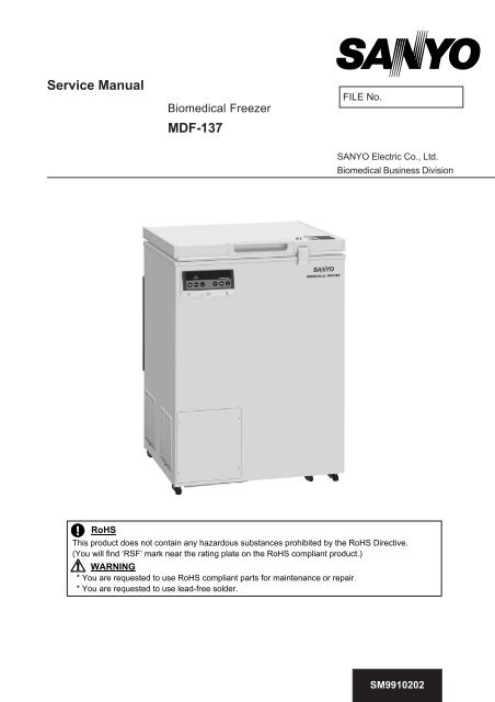
Service Manual MDF-137 - Panasonic Biomedical
Service Manual MDF-137 - Panasonic Biomedical
Service Manual MDF-137 - Panasonic Biomedical

Create successful ePaper yourself
Turn your PDF publications into a flip-book with our unique Google optimized e-Paper software.
<strong>Service</strong> <strong>Manual</strong><br />
<strong>Biomedical</strong> Freezer<br />
<strong>MDF</strong>-<strong>137</strong><br />
FILE No.<br />
SANYO Electric Co., Ltd.<br />
<strong>Biomedical</strong> Business Division<br />
RoHS<br />
This product does not contain any hazardous substances prohibited by the RoHS Directive.<br />
(You will find ‘RSF’ mark near the rating plate on the RoHS compliant product.)<br />
WARNING<br />
* You are requested to use RoHS compliant parts for maintenance or repair.<br />
* You are requested to use lead-free solder.<br />
SM9910202
Effective models<br />
This service manual is effective following models.<br />
Model name Product code Voltage and Frequency<br />
<strong>MDF</strong>-<strong>137</strong> 823 016 54 220-240V 50Hz
Contents<br />
<br />
Features --------------------------------------------------- 1<br />
Specifications --------------------------------------------------- 2<br />
- Structural specifications<br />
- Performance specifications<br />
- Control specifications<br />
Dimensions --------------------------------------------------- 4<br />
Cooling unit parts ---------------------------------------------- 5<br />
Refrigeration circuit -------------------------------------- 6<br />
Components on PCB -------------------------------------- 7<br />
Connections on PCB -------------------------------------- 8<br />
Electric parts ---------------------------------------------- 9<br />
Specifications of sensor -------------------------------------- 10<br />
Wiring diagram ---------------------------------------------- 11<br />
Circuit diagram ---------------------------------------------- 12<br />
Control specifications -------------------------------------- 13<br />
Installation of compressor terminal cover ---------------------- 21<br />
Parts layout --------------------------------------------------- 24<br />
Test data --------------------------------------------------- 27<br />
- Pull-down & Pull-up temperature<br />
- Pull-down pressure<br />
- Pull-down power consumption<br />
- Temperature uniformity data (15points measured)<br />
- Amount of power consumption when driving at cycle<br />
Instruction manual ---------------------------------------------------- 33
Features<br />
Cooling performance<br />
- New compressor realizes chamber temperature can maintain -30 at least when<br />
ambient temperature is 35.<br />
Environment conscious<br />
- HFC refrigerant, R-134a is adopted.<br />
- CP urethane foaming is adopted for frame insulation.<br />
Better reliability for storage<br />
- Various function modes are added by flash memory.<br />
- Battery age is informed by counting battery accumulation time.<br />
- Delay time for temperature alarm is changeable.<br />
- New door lock mechanism<br />
1
Specifications<br />
Structural specifications<br />
Item<br />
Specifications<br />
Name<br />
<strong>Biomedical</strong> Freezer<br />
Model<br />
<strong>MDF</strong>-<strong>137</strong><br />
External dimensions<br />
W640 x D687 x H881 mm<br />
Internal dimensions<br />
W525 x D440 x H715 mm<br />
Effective capacity<br />
138 L<br />
Exterior<br />
Painted steel<br />
Interior<br />
Colored aluminum plate<br />
Insulation<br />
Rigid polyurethane foamed-in place<br />
Door<br />
Painted steel<br />
Lock<br />
1 pc, cylinder type<br />
Compressor<br />
Hermetic type, Output: 150W<br />
Evaporator<br />
Aluminum tube on sheet type<br />
Condenser<br />
Wire and tube type<br />
Refrigerant<br />
R-134a<br />
Battery<br />
For power failure alarm, Nickel-metal-hydride battery, DC6V, 1100mAh<br />
Automatic charge<br />
Accessories<br />
1 set of key, 1 scraper, 2 baskets<br />
Caster<br />
4 pcs<br />
Leveling foot<br />
2 pcs at front<br />
Access port<br />
17mm at right side and bottom left<br />
Weight<br />
52 Kg<br />
Automatic temperature recorder: MTR-4015LH, MTR-G85<br />
Mounting kit for automatic temperature recorder:<br />
<strong>MDF</strong>-S3040 (for MTR-4015LH)<br />
Optional components<br />
<strong>MDF</strong>-S740for MTR-G85<br />
2 baskets: <strong>MDF</strong>-13B2<br />
MTR-480C<br />
MTR-L03<br />
MTR-5000<br />
Performance specifications<br />
Item<br />
Specifications<br />
Cooling performance<br />
-30AT:35, no load<br />
Temperature control range<br />
-20-30<br />
Rated voltage AC220V AC230V AC240V<br />
Rated frequency 50Hz 50Hz 50Hz<br />
Rated power consumption 95W 100W 100W<br />
Noise level<br />
35 dB (background noise; 20dB)<br />
Maximum pressure<br />
1.64 MPa<br />
2
Control specifications<br />
Item<br />
Temp. controller<br />
Temp. sensor<br />
Temp. display<br />
Alarms<br />
Control panel<br />
Key Lock<br />
Self diagnosis<br />
Power switch<br />
Power source<br />
High temp.<br />
Low temp.<br />
Remote<br />
alarm<br />
Power fail.<br />
Specifications<br />
Microcomputer input by keypad<br />
Setting range: -18-351 increment<br />
Non-volatile memory<br />
Thermistor sensor<br />
LED digital display (1 increment)<br />
Display range: -5050<br />
Set temperature5+15, changeableDefault: +10<br />
ALARM lamp blinks and buzzer sounds intermittently<br />
with 15 min. of delay<br />
Remote alarm contact activates and joins with buzzer<br />
Set temperature-5-15, changeableDefault: -10<br />
ALARM lamp blinks and buzzer sounds intermittently<br />
with 15 min. of delay<br />
Remote alarm contact activates and joins with buzzer<br />
Remote alarm terminal 3P: Contact capacity DC30V, 2A (Max)<br />
NC-COMNO-COM<br />
Activates during high/low temp. alarm, power failure alarm and Alarm<br />
test performed, joins with buzzer<br />
ALARM lamp blinks, buzzer sounds intermittently and remote alarm<br />
contact activates.<br />
ALARM: Alarm lamp<br />
BUZZER: Alarm buzzer stop key<br />
ALARM TEST: Alarm test key<br />
SET: Set key<br />
: Digit shift key<br />
: Numerical value shift key<br />
DEF: Defrost key<br />
Press key for 5 seconds.<br />
L0: Unlocked<br />
L1: Locked<br />
* When temp. sensor is failed;<br />
- Error codeE01/E02 and chamber temp. are displayed alternately.<br />
- Remote alarm contact activates with buzzer sounds.<br />
* When battery switch OFF check is failed in Alarm Test;<br />
- Error codeE09 and chamber temp. are displayed alternately.<br />
Breaker switch on left back side<br />
Local voltage<br />
3
Dimensions<br />
4
<strong>MDF</strong>-<strong>137</strong><br />
Cooling unit parts<br />
Parts name<br />
Specifications<br />
Compressor<br />
Type<br />
FL1568-SP<br />
Compressor cord 7FB-2-M101-010-03<br />
Rated power supply Single phase, 220~240V, 50Hz<br />
Oil<br />
Charged qty: 310±10ml<br />
Cooling method<br />
Natural air circulation<br />
PTC<br />
PGR0SAT<br />
Overload relay<br />
2.0C36C3<br />
Starting capacitor 60µF-300VAC<br />
Running capacitor -----<br />
Evaporator Type Direct cooling tube on sheet type<br />
Dryer<br />
Type<br />
4A-XH-9<br />
Charged qty<br />
10g<br />
Capillary tube Resistance<br />
0.725 MPaG<br />
LengthL<br />
3600 mm<br />
Outer diameterOD 1.8 mm<br />
Inner diameterID (0.65 mm)<br />
Condenser<br />
Type<br />
Natural convection<br />
Condenser<br />
Wire and tube type<br />
24 lines × P40mm × W440 mm<br />
Pre-condenser<br />
Wire and tube type<br />
4 lines × P40mm × W440 mm<br />
Frame pipe<br />
4.76C1220T<br />
Refrigerant Type R-134a Charged qty: 160±5g<br />
5
Refrigeration circuits <br />
<br />
<br />
Frame pipe<br />
Condenser<br />
Evaporator<br />
Pre condenser<br />
Dryer<br />
Capillary tube<br />
Header<br />
Compressor<br />
Point to evacuate<br />
6
Components on PCB<br />
CN8<br />
To Battery<br />
Battery Switch<br />
CN1<br />
To Switching<br />
Power supply<br />
CN7<br />
#9-#10<br />
To Temp.sensor<br />
CN2<br />
To MTR-480<br />
(Option)<br />
CN6<br />
To Display PCB (CN52)<br />
CN4<br />
#1-#2<br />
To Temp. control relay<br />
CN5<br />
#1-#6 To Display PCB(CN51)<br />
#7-#8 To Buzzer<br />
CN3<br />
To Remote alarm terminal<br />
7
Connections on PCB<br />
Connectors on Temp. control PCB<br />
Connector Connects to Usage<br />
CN1<br />
Switching power supply<br />
1 +12VDC<br />
3 GND<br />
To supply the power to PCB<br />
CN2<br />
MTR-480Option<br />
CN3<br />
Remote alarm terminal<br />
1 COM<br />
2 N.C.(When power is not supplied)<br />
3 N.O.(When power is not supplied)<br />
Output for remote alarm contact<br />
Open between #1 and #2 when the<br />
power is supplied in normal condition.<br />
#1 and #2 are connected with remote<br />
alarm terminal.<br />
CN4<br />
Temp. control relay<br />
#1: +12V (When temp. control relay is ON)<br />
#2: GND<br />
To turn temp. control relay on/off<br />
CN5 Display PCB (CN51) To connect with each of switches<br />
CN6 Display PCB (CN52) To connect with each of LED<br />
CN7<br />
Temp. sensor<br />
#9 - #10 Temp. sensor<br />
To sense chamber temperature<br />
CN8 Battery6V To connect with battery for power failure<br />
8
Electric parts<br />
<strong>MDF</strong>-<strong>137</strong><br />
220~240V, 50Hz<br />
Compressor Type FL1568-SP<br />
Compressor cord<br />
7FB-2-M101-010-03<br />
Rating<br />
220~240V, 50Hz<br />
Winding resistance(25) C-R 11.4<br />
C-S 19.5<br />
PTC Type PGR0SAT<br />
Resistance25<br />
336.6<br />
O.L. relay Type 2.0C36C3<br />
Action to the temp.<br />
+8<br />
+7<br />
ON:130 -9 OFF:60 -5 <br />
Action to the current (AT25)<br />
7.6 A<br />
Non-action to the temp.<br />
Operation time<br />
10 sec<br />
Starting capacitor Rating 60µF, 300VAC<br />
Temp. control relay Type G4F-11123T<br />
Contact capacity<br />
20A<br />
Coil<br />
12VDC<br />
Temp. sensor Type 502AT-1<br />
Rating<br />
5K, 25<br />
Switching power supply Type LDA10F-12<br />
Rated output 12VDC, 0.9A<br />
Breaker switch Type BAM215131<br />
Rating<br />
250VAC, 15A<br />
Battery switch Type SLE6A2-5<br />
Rating<br />
250VAC, 4A<br />
Battery<br />
Type<br />
5HR-AAC(Ni-MH)<br />
Rating<br />
6V, 1100mAH<br />
9
Specifications of sensor<br />
Type: 502AT-1<br />
k k k k<br />
50 154.5 36 71.80 22 35.65 0 13.29<br />
49 145.9 35 68.15 21 33.99 5 10.80<br />
48 <strong>137</strong>.8 34 64.71 20 32.43 10 8.84<br />
47 130.2 33 61.48 19 30.92 15 7.20<br />
46 123.1 32 58.43 18 29.50 20 6.01<br />
45 116.5 31 55.55 17 28.14 25 5.00<br />
44 110.2 30 52.84 16 26.87 30 4.17<br />
43 104.4 29 50.23 15 25.65 35 3.50<br />
42 98.87 28 47.77 14 24.51 40 2.96<br />
41 93.70 27 45.45 13 23.42 45 2.51<br />
40 88.85 26 43.26 12 22.39 50 2.13<br />
39 84.18 25 41.19 11 21.41 55 1.82<br />
38 79.80 24 39.24 10 20.48 60 1.56<br />
37 75.67 23 37.39 5 16.43 65 1.35<br />
<br />
<br />
<br />
10
Wiring Diagram<br />
11
Control specifications<br />
1. Keys and Switches<br />
BUZZER : When alarm lamp blinks and buzzer sounds, buzzer and remote alarm<br />
output ……… Forced to be turned off<br />
Buzzer is not turned off during alarm test.<br />
When alarm lamp blinks and buzzer is turned off, buzzer never activates.<br />
In power failure, press the key to display the current temperature for 5<br />
seconds.<br />
SET : Press once this key to enter into setting mode with 2 nd digit blinks.<br />
Press this key again to memorize the value. (it works as ENTER key)<br />
DEF : In chamber temperature display, press this key for 5 seconds to start<br />
defrosting.<br />
In defrosting, press this key to have defrosting to the end.<br />
In defrosting, chamber temperature and “dF” are displayed alternately.<br />
In defrosting, temperature alarm is cancelled.<br />
When the sensor error is occurred In defrosting, error code and chamber<br />
temperature are displayed alternately. “dF” is gone off.<br />
In defrosting, only the buzzer key is operative.<br />
ALARM TEST : In chamber temperature display, press the key for 5 seconds to activate<br />
alarm test mode. ALARM lamp blinks, buzzer sounds intermittently and the<br />
display goes off and remote alarm activates.<br />
Automatically returns to normal condition after 90 seconds passed even if<br />
you don’t press this key. (Auto Return)<br />
When you perform alarm test with battery switch is off position, ‘E09’ blinks.<br />
During setting mode, press this key to change the digit one by one. In<br />
chamber temperature display, press this key for 5 seconds to enter into Key<br />
Lock mode with “L_0” display.<br />
During setting mode, press this key to count the digit up one by one. In<br />
chamber temperature display, press this key for 5 seconds to enter into<br />
Function mode with “F00” display.<br />
Input each function code by pressing key and key.<br />
2. Temperature control<br />
Setting range : -18-35<br />
Display range : -50+50<br />
Setting process : Press SET key and set the required value with key and key.<br />
Press SET key again to memorize the set value, and then automatically<br />
return to chamber temperature display.<br />
Unacceptable setting<br />
range:<br />
When you input a value in unacceptable setting range and press SET<br />
key, error tone is emitted.<br />
3. Key Lock Function<br />
Setting range : 0 or 1<br />
Setting process In chamber temperature display, press key for 5seconds to enter into<br />
Key Lock mode with “L_0” display. Change the 1 st digit and press SET<br />
key to memorize the value in non-volatile memory.<br />
1: Locked<br />
0: Unlocked<br />
13
4. Function mode<br />
Setting range : 0~50<br />
Display range : 0~59<br />
Note) 04, 08, 13, 15, 16, 18~20, 26~29, 31, 33~49 are unused.<br />
Setting process : In chamber temperature display, press key for 5 seconds to enter into<br />
Function mode with ‘F00’ display. Change the 1 st digit with key and<br />
Unacceptable setting<br />
range:<br />
key.<br />
When you input a value in unacceptable setting range and press SET<br />
key, error tone is emitted.<br />
5. Error code<br />
E01: Temp. sensor is disconnected.<br />
When temp. sensor is disconnected, ‘E01’ and ‘50’ are displayed<br />
alternately.<br />
Buzzer sounds and remote alarm activates.<br />
Compressor is turned on.<br />
Press BUZZER key to stop buzzer sounding.<br />
Remote alarm keeps activating.<br />
E02: Temp. sensor is short circuited.<br />
When temp. sensor is short circuited, ‘E02’ and ‘-50’ are displayed<br />
alternately.<br />
Buzzer sounds and remote alarm activates.<br />
Compressor is turned on.<br />
Press BUZZER key to stop buzzer sounding.<br />
Remote alarm keeps activating.<br />
E09: Battery switch is OFF<br />
When battery switch is off position or battery is unconnected, press<br />
ALARM key to display ‘E09’.<br />
6. Alarms<br />
High temp. alarm : When chamber temperature is equal or higher than setting temperature +<br />
high temp. alarm setting temperature + 1.0, ALARM lamp and the digital<br />
display blink. After 10min. later, buzzer sounds and remote alarm output<br />
activates.<br />
When chamber temperature is equal or lower than setting temperature,<br />
ALARM lamp and the digital display go off, buzzer stops sounding and<br />
remote alarm output turns off.<br />
If you press BUZZER key, buzzer stops sounding. Remote alarm keeps<br />
activating.<br />
High temp. alarm setting range: ‘005’ ~ ‘015’<br />
Default setting: ‘010’<br />
Low temp. alarm : When chamber temperature is equal or lower than setting temperature -<br />
low temp. alarm setting temperature - 1.0, ALARM lamp and the digital<br />
display blink. After 10min. later, buzzer sounds and remote alarm output<br />
activates.<br />
When chamber temperature is equal or higher than setting temperature,<br />
ALARM lamp and the digital display go off, buzzer stops sounding and<br />
remote alarm output turns off.<br />
If you press BUZZER key, buzzer stops sounding. Remote alarm keeps<br />
activating.<br />
Low temp. alarm setting range: ‘-05’ ~ ‘-15’<br />
Default setting: ‘-10’<br />
14
Power failure alarm :<br />
When power switch is off position or power is not supplied for 3 seconds<br />
with battery switch ON, ALARM lamp blinks, buzzer sounds intermittently<br />
and remote alarm activates.<br />
When the power is retrieved within 3 seconds since the power failed, the<br />
apparatus restarts with initial operation.<br />
Remote alarm turns off.<br />
Press BUZZER key to stop buzzer sounding.<br />
Remote alarm keeps activating.<br />
Remote alarm keeps activating until chamber temperature is stabled after<br />
the power retrieves from power failure.<br />
If you press BUZZER key during power failure, you can check chamber<br />
temperature for 5 seconds.<br />
7. Auto Return<br />
If there are not any key operations for 90 seconds in setting mode, Key Lock mode and Function<br />
mode, the value would not be memorized and automatically returns to chamber temperature<br />
display.<br />
8. Alarm resume time (Ring Back)<br />
Buzzer sounds again after alarm resume time elapses even if someone intends to stop buzzer<br />
sounding by pressing BUZZER key during alarm condition.<br />
Alarm resume time is changeable in F25.<br />
9. Temperature in temp. sensor<br />
The 1 st decimal point of the temperature in temp. sensor is displayed in F12.<br />
Ex) -30.2 => Displayed as ’30.2’<br />
10. Battery accumulation period<br />
Battery accumulation period is displayed in F03.<br />
Ex) 2 years and 6 months => Displayed as ’02.5’<br />
When battery accumulation period is ’02.8’, ‘F-1’ and chamber temperature are displayed<br />
alternately.<br />
How to reset battery accumulation period:<br />
Input ‘409’ in F06 and press SET key to clear accumulation period to ’00.0’.<br />
‘F-1’ is disappeared on the display.<br />
11. ROM version<br />
Current ROM version is displayed in F30.<br />
Ex) Ver. 1.00 => Displayed as ‘1.00’<br />
15
12. Function mode<br />
Function modes are as follow.<br />
F00: Automatically return to chamber temperature display<br />
F01: Setting of temperature for high temperature alarm<br />
F02: Setting of temperature for low temperature alarm<br />
F03: Display of Battery accumulation period<br />
F05: Setting of compressor delay time<br />
F06: <strong>Service</strong> code input (384)<br />
F07: Temperature Zero calibration<br />
F12: Display of temperature in temperature sensor (The decimal point is displayed)<br />
F17: Setting of model code (Initialization for non-volatile memory)<br />
F21: Setting of communication ID<br />
F22: Setting of communication mode<br />
F24: Joint operation for remote alarm and buzzer<br />
F25: Setting of alarm resume time (Ring Back)<br />
F26: Display of running rate<br />
F30: Display of ROM version<br />
F50: Setting of temperature alarm delay time<br />
Setting process:<br />
Note)<br />
In chamber temperature display, press key for 5seconds to display<br />
“F00”.<br />
Press key to input required function code and press SET key.<br />
Ensure to input service code ‘384’ in F06 prior to use F07, F12, F17, F24,<br />
F26 and F30. It is unnecessary to input service code when you use<br />
F00~F06, F21, F22 and F25.<br />
<strong>Service</strong> code ‘384’ is cancelled if you input ‘000’ in F06 or turn the power off<br />
F00: It is not functioned. In F00 displayed, press SET key to return to chamber<br />
temperature display.<br />
F01: Setting of temperature for high temp. alarm<br />
Setting range is ‘005’ ~ ‘015’<br />
Input F01 and press SET key to display ‘010’ (Default setting).<br />
Change to your required value and press SET key to memorize and return to<br />
chamber temperature display.<br />
F02: Setting of temperature for low temp. alarm<br />
Setting range is ‘-05’ ~ ‘-15’<br />
Input F02 and press SET key to display ‘-10’ (Default setting).<br />
Change to your required value and press SET key to memorize and return to<br />
chamber temperature display.<br />
F03: Display of battery accumulation period<br />
Input F03 and press SET key to display F03 and battery accumulation period<br />
alternately. Press SET key to return to chamber temperature display.<br />
’00.0’ = Battery accumulation period is less than 36days<br />
F05: Setting of compressor delay time (This function is performed when the main power is<br />
turned on or power is retrieved from power failure)<br />
Setting range is ‘003’~’015’.<br />
Press SET key to memorize the value and return to chamber temperature display.<br />
F06: Input F06 and press SET key to display ‘000’ (default setting).<br />
Input the service code with key and key. (<strong>Service</strong> code: 384)<br />
press SET key to memorize service code and return to chamber temperature display.<br />
16
Input service code, 384 and ‘409’ to reset battery accumulation time.<br />
Return to chamber temperature display.<br />
If you want to cancel the service code, input F06 to display ‘384’.<br />
Change the value to ‘000’ with key and key.<br />
If you turn the power off then on, the display is also returned to ‘000’.<br />
F07: Zero Adjustment of temperature sensor (setting range: -4.9~+04.9)<br />
This function is used for adjustment between display temperature and 1/2H air<br />
temperature.<br />
In “F07” displayed, press SET key to display “00.0”(default setting), then change the<br />
value with key and key. Press again SET key to memorize the value.<br />
<br />
When the actual 1/2H air temperature is -26 and setting temperature is –30,<br />
input F07 and press SET key to display ’00.0’.<br />
Change the value to ’04.0’ and press SET key.<br />
About 4 is added to display temperature and chamber temperature is gradually<br />
lowered to -30.<br />
F12: Display of temperature in temperature sensor<br />
Input F12 and press SET key to display F12 and ‘XX.X’ (current chamber<br />
temperature) alternately. Press SET key to revert to chamber temperature display.<br />
It is not shown “-“ (minus) when the temperature is lower than -20.0.<br />
(Ex. Actual temp -20.5 Display shows as ‘20.5’)<br />
F17: Setting of model code (001: <strong>MDF</strong>-<strong>137</strong>)<br />
In “F17” displayed, press SET key to display model code ‘001’.<br />
Press SET key again to memorize the value.<br />
<br />
Zero adjustment value for temp. sensor : -30<br />
Alarm resume (Ring Back) time : 30 minutes<br />
Setting temperature : -30<br />
Setting temp. for high temp. alarm : +10<br />
Setting temp. for low temp. alarm : -10<br />
Joint operation for remote alarm : Not joined<br />
and buzzer<br />
Compressor delay time<br />
: 3 minutes<br />
Communication ID : 000<br />
Communication mode : 000<br />
Delay time for temp. alarm<br />
: 15 minutes<br />
Key Lock<br />
: OFF<br />
17
F21: Serial communication ID setting (Range: 000~255)<br />
Input F21 and press SET key to display ‘000’ (default value).<br />
Press SET key to memorize the value and return to chamber temperature display.<br />
<br />
Data<br />
Display value<br />
Chamber temperature<br />
: -73.3 ~ +78.4<br />
Temperature in comp. sensor<br />
: -70.8 ~ +159.5<br />
Compressor operation<br />
: 0(OFF) / 100(ON)<br />
Power failure<br />
: 0(OFF) / 100(ON)<br />
Operation ratio : 0~100, 222 %<br />
2H timer count<br />
: 0~120 minutes<br />
8H timer count<br />
: 0~480 minutes<br />
Setting temperature<br />
: -35.0 ~ -18.0<br />
High temp. alarm setting temp.<br />
: +5.0~+15.0<br />
Low temp. alarm setting temp.<br />
: -5.0~-15.0<br />
High temp. alarm operation<br />
: 0(OFF) / 50(ON)<br />
Low temp. alarm operation<br />
: 0(OFF) / 50(ON)<br />
Remote alarm operation<br />
: 0(OFF) / 50(ON)<br />
Range for changing chamber temp. : -25.0~-18.0<br />
F22: Serial communication mode setting<br />
Control mode (3 rd digit) 0:<br />
1:<br />
Baud rate (2 nd digit) 0:<br />
1:<br />
2:<br />
Local (initial value)<br />
Remote<br />
2400 bps (initial value)<br />
4800 bps<br />
9600 bps<br />
1 st digit is not used.<br />
Note) It is unable to change setting temperature when you set control mode at<br />
“remote”.<br />
F24: Joint operation for remote alarm and buzzer<br />
Input F24 and press SET key to display ‘000’ (default setting).<br />
Change to your required setting by key.<br />
Press SET key again to revert to chamber temperature display.<br />
000: Not joined<br />
001: Joined<br />
F25: Setting of alarm resume time (Ring Back)<br />
Input F25 and press SET key to display ‘030’ (default setting).<br />
Change to your required setting by key. Range: 000~060<br />
Press SET key again to revert to chamber temperature display.<br />
000: Not resumed 040: 40 minutes<br />
010: 10 minutes 050: 50 minutes<br />
020: 20 minutes 060: 60 minutes<br />
030: 30 minutes<br />
F26: Display of operation ratio<br />
Input F26 and press SET key to display F26 and ‘XXX’ (current operation ratio)<br />
alternately. Press SET key again to revert to chamber temperature display.<br />
F30: Display of ROM version<br />
Input F30 and press SET key to display F30 and ‘X.XX’ (current ROM version)<br />
alternately. Press SET key again to revert to chamber temperature display.<br />
18
F50: Setting of temperature alarm delay time<br />
Input F50 and press SET key to display ‘015’ (default setting). Change to your<br />
required setting by key and key. Range: 000~015<br />
Press SET key to memorize the value and revert to chamber temperature display.<br />
000: Not delayed<br />
13. Compressor operation for temperature control<br />
When chamber temperature is equal to set temperature<br />
When chamber temperature is 0.6 lower than<br />
set temperature<br />
: Compressor turns on<br />
: Compressor turns off<br />
14. Delay time<br />
(1) Compressor delay time (Default: 3 minutes)<br />
Compressor should be started with delay after the power is supplied.<br />
Setting is changeable in F05.<br />
Compressor would not restart next 3 minutes (fixed value) in case it turns off during cycle<br />
operation.<br />
(2) Temperature alarm delay time (Default: 10 minutes)<br />
When unit is in high/low temperature alarm condition, buzzer and remote alarm activate with<br />
delay time. Display blinks and ALARM lamp is lit without delay.<br />
Setting value is changeable in F50.<br />
15. Temperature offset<br />
Input offset value to adjust for temperature in temp. sensor with actual temperature.<br />
Temp. sensor offset value is -4.0.<br />
You can change offset value in F07. (Range: -4.9~+4.9)<br />
16. Display offset<br />
Offset value for display is displayed value -0.5.<br />
17. Operation for remote alarm<br />
Connector<br />
CN3<br />
Status #1 - #2 (N.O.) #1 - #3 (N.C.)<br />
Normal Open Close<br />
Alarming Close Open<br />
18. Lamp operation<br />
DP51 (Red) on display PCB: ALARM lamp blinks during alarming conditions.<br />
DP1 (Orange) on control PCB: Lit in normal condition<br />
Goes off in high/low temp. alarm (with 15min. delay), in sensor<br />
errors, in power failure<br />
DP2 (Green) on control PCB: Lit during compressor operating<br />
Goes off during compressor turns off<br />
19
19. Examples of display<br />
Chamber temp. -29.5 Decimal point of chamber temp. -80.0<br />
Set temp. -30.0 Sensor offset -4.9<br />
Function code<br />
F03<br />
Error E01<br />
<strong>Service</strong> code 384<br />
Set value 004<br />
Key Lock <br />
L_0<br />
20. Buzzer tone<br />
Intermittent tone: In alarming condition<br />
Click tone : In key operation<br />
In memorize setting value<br />
Continuous tone: Ineffective setting value<br />
20
Installation of compressor terminal cover<br />
1<br />
<br />
<br />
Fixing bar<br />
<br />
Hang fixiing bar on the both holes of the<br />
terminal. Then move the bar to the right side.<br />
2<br />
Upsid<br />
e<br />
Terminal cover<br />
Put lead wires into the terminal cover.<br />
3<br />
Connect PTC and OLR with the specified color<br />
lead wires. (Refer to Wiring diagram)<br />
Terminal cover<br />
OLR<br />
PTC<br />
21
4<br />
Violet<br />
Terminal cover<br />
(Partially cut for explanation)<br />
PTC<br />
L.blue<br />
Projection of Terminal cover<br />
Squarish hole<br />
5<br />
Blue<br />
Fit PTC with terminal cover.<br />
Put the projection of terminal cover<br />
in the squarish hole (See picture (4))<br />
6<br />
Inside of terminal cover<br />
22
7<br />
Mount terminal cover on compressor terminal.<br />
Move the fixing bar back to original position and<br />
fix the bar on 2 projections with a snap.<br />
Projection<br />
*** For the removal of terminal cover, follow the above process vice versa.<br />
23
Temperature control sensor cover<br />
Load Line<br />
Temperature control sensor (Loaded)<br />
Entrance of temperature control sensor<br />
on the back<br />
Temperature<br />
control sensor<br />
connector insert<br />
Bend Temperature control sensor<br />
to attach load with it<br />
Access port<br />
(for recorder sensor)<br />
Lock<br />
Connection terminal<br />
for Recorder (with socket)<br />
25
Remote alarm<br />
Battery SW<br />
Power SW<br />
Terminal for MTR-480<br />
(Option)<br />
Remote alarm<br />
Battery SW<br />
Battery<br />
DP1 is lit in power failure alarm<br />
DP2 is lit when compressor is operating<br />
26
Test data<br />
* All the data are the reference only.<br />
AT35 Pull-down & Pull-up Temperture<br />
Temperture[]<br />
40<br />
30<br />
20<br />
10<br />
0<br />
1/2H220V<br />
1/2H230V<br />
-10<br />
1/2Hpullup<br />
-20<br />
-30<br />
-40<br />
0 1 2 3 4<br />
Time[hour]<br />
AT35Pull-down Pressure<br />
Pressure[MPa]<br />
2<br />
1.8<br />
1.6<br />
1.4<br />
1.2<br />
1<br />
0.8<br />
0.6<br />
0.4<br />
0.2<br />
0<br />
Pd(220V)<br />
Pd(230V)<br />
Ps(220V)<br />
Ps(230V)<br />
0 1 2 3 4<br />
Time[hour]<br />
AT35Pull-downPower consumption<br />
Power consumption[W]<br />
250<br />
200<br />
150<br />
100<br />
50<br />
Input220V<br />
Input230V<br />
Current220V<br />
Current230V)<br />
5<br />
4<br />
3<br />
2<br />
1<br />
Current[A]<br />
0<br />
0 1 2 3 4<br />
Time[hour]<br />
0<br />
27
Temperature Uniformity data (15points measured)<br />
*All the data are the reference only.<br />
<br />
<br />
<br />
<br />
<br />
<br />
<br />
<br />
<br />
<br />
<br />
<br />
<br />
<br />
<br />
<br />
<br />
<br />
<br />
<br />
<br />
<br />
<br />
<br />
<br />
<br />
<br />
<br />
<br />
<br />
<br />
<br />
<br />
<br />
<br />
<br />
<br />
<br />
<br />
<br />
<br />
<br />
<br />
<br />
<br />
<br />
<br />
<br />
<br />
<br />
<br />
28
Conditions<br />
Ambient temperature: 20/30<br />
Load: Unloaded<br />
Distribution data<br />
Amount of power consumption<br />
Temperature of the cycle in each area (SV=-30air temperature)<br />
Amount of power consumption when driving at cycle<br />
Unit:<br />
(SV=-30<br />
Ambient temperature 20<br />
UnitkWh/day<br />
220V50Hz 230V50Hz Ambient temp 20 Ambient temp 30<br />
Maximum Minimum<br />
Middle of<br />
Middle of<br />
Differential Maximum Minimum Differential<br />
cycle<br />
cycle<br />
50Hz<br />
50Hz<br />
-27.8 -29.9 -28.9 ±1.1 -27.8 -29.8 -28.8 ±1.0 220V 1.47 1.87<br />
-28.1 -31.3 -29.7 ±1.6 -28.3 -31.2 -29.8 ±1.5 230V 1.50<br />
1.91<br />
-28.1 -31.0 -29.6 ±1.5 -28.3 -31.0 -29.7 ±1.4 240V 1.55<br />
2.08<br />
-28.1 -31.4 -29.8 ±1.7 -28.3 -31.3 -29.8 ±1.5<br />
Note:This data does not represent a guarantee<br />
-28.9 -30.6 -29.8 ±0.9 -29.1 -30.6 -29.9 ±0.8<br />
of product performance.<br />
-29.2 -32.5 -30.9 ±1.7 -29.4 -32.4 -30.9 ±1.5<br />
-28.9 -32.0 -30.5 ±1.6 -29.1 -32.0 -30.6 ±1.5<br />
-28.9 -31.9 -30.4 ±1.5 -29.1 -31.9 -30.5 ±1.4<br />
-28.8 -32.1 -30.5 ±1.7 -28.9 -32.2 -30.6 ±1.7<br />
-29.6 -31.1 -30.4 ±0.8 -29.6 -31.0 -30.3 ±0.7<br />
-29.7 -32.6 -31.2 ±1.5 -29.7 -32.7 -31.2 ±1.5<br />
-28.9 -30.6 -29.8 ±0.9 -28.9 -30.7 -29.8 ±0.9<br />
-29.5 -31.5 -30.5 ±1.0 -29.5 -31.7 -30.6 ±1.1<br />
-28.6 -30.3 -29.5 ±0.9 -28.6 -30.4 -29.5 ±0.9<br />
-29.9 -32.0 -31.0 ±1.1 -30.0 -32.6 -31.3 ±1.3<br />
Average - - -30.1 - - - -30.2 -<br />
Unit:<br />
Ambient temperature 30<br />
220V50Hz<br />
230V50Hz<br />
Maximum Minimum<br />
Middle of<br />
Middle of<br />
Differential Maximum Minimum Differential<br />
cycle<br />
cycle<br />
-26.2 -28.1 -27.2 ±1.0 -26.2 -28.0 -27.1 ±0.9<br />
-26.7 -29.4 -28.1 ±1.4 -26.7 -29.4 -28.1 ±1.4<br />
-26.7 -29.1 -27.9 ±1.2 -26.8 -29.1 -28.0 ±1.2<br />
-26.8 -29.5 -28.2 ±1.4 -26.8 -29.5 -28.2 ±1.4<br />
-27.7 -29.0 -28.4 ±0.7 -27.6 -29.0 -28.3 ±0.7<br />
-28.2 -31.0 -29.6 ±1.4 -28.1 -31.0 -29.6 ±1.5<br />
-28.0 -30.2 -29.1 ±1.1 -27.9 -30.3 -29.1 ±1.2<br />
-27.8 -30.3 -29.1 ±1.3 -27.8 -30.4 -29.1 ±1.3<br />
-27.6 -30.7 -29.2 ±1.6 -27.6 -30.8 -29.2 ±1.6<br />
-28.5 -30.0 -29.3 ±0.8 -28.5 -30.0 -29.3 ±0.8<br />
-28.5 -31.6 -30.1 ±1.6 -28.5 -31.6 -30.1 ±1.6<br />
-27.6 -29.4 -28.5 ±0.9 -27.5 -29.3 -28.4 ±0.9<br />
-28.5 -31.4 -30.0 ±1.5 -28.4 -31.4 -29.9 ±1.5<br />
-27.3 -29.1 -28.2 ±0.9 -27.2 -29.1 -28.2 ±1.0<br />
-28.8 -31.9 -30.4 ±1.6 -28.8 -31.8 -30.3 ±1.5<br />
Average - - -28.9 - - - -28.8 -<br />
Note:This data does not represent a guarantee of product performance.<br />
29
Distribution data<br />
Amount of power consumption<br />
Temperature of the cycle in each area (SV=-20air temperature)<br />
Amount of power consumption when driving at cycle<br />
Unit:<br />
(SV=-20<br />
Ambient temperature 20<br />
UnitkWh/day<br />
220V50Hz<br />
230V50Hz<br />
Ambient temp. 20 Ambient temp. 30<br />
Maximum Minimum<br />
Middle of<br />
Middle of<br />
Differential Maximum Minimum Differential<br />
cycle<br />
cycle<br />
50Hz<br />
50Hz<br />
-17.5 -20.5 -19.0 ±1.5 -17.5 -20.5 -19.0 ±1.5 220V<br />
- 1.41<br />
-17.7 -21.9 -19.8 ±2.1 -17.7 -22.0 -19.9 ±2.2 230V 1.07<br />
1.44<br />
-17.8 -21.6 -19.7 ±1.9 -17.8 -21.6 -19.7 ±1.9 240V 1.08 1.48<br />
-17.7 -22.0 -19.9 ±2.2 -17.7 -22.1 -19.9 ±2.2<br />
Note:This data does not represent a guarantee<br />
-18.7 -20.9 -19.8 ±1.1 -18.7 -20.9 -19.8 ±1.1<br />
of product performance.<br />
-18.7 -23.0 -20.9 ±2.2 -18.7 -23.1 -20.9 ±2.2<br />
-18.7 -22.5 -20.6 ±1.9 -18.7 -22.6 -20.7 ±2.0<br />
-18.6 -22.4 -20.5 ±1.9 -18.6 -22.5 -20.6 ±2.0<br />
-18.5 -22.7 -20.6 ±2.1 -18.5 -22.8 -20.7 ±2.2<br />
-19.3 -21.5 -20.4 ±1.1 -19.3 -21.5 -20.4 ±1.1<br />
-19.1 -23.2 -21.2 ±2.1 -19.1 -23.3 -21.2 ±2.1<br />
-18.9 -21.3 -20.1 ±1.2 -18.9 -21.3 -20.1 ±1.2<br />
-19.1 -23.0 -21.1 ±2.0 -19.1 -22.5 -20.8 ±1.7<br />
-18.6 -21.1 -19.9 ±1.3 -18.6 -21.0 -19.8 ±1.2<br />
-19.4 -23.5 -21.5 ±2.1 -19.4 -23.4 -21.4 ±2.0<br />
Average - - -20.3 - - - -20.3 -<br />
Unit:<br />
Ambient temperature 30<br />
220V50Hz<br />
230V50Hz<br />
Maximum Minimum<br />
Middle of<br />
Middle of<br />
Differential Maximum Minimum Differential<br />
cycle<br />
cycle<br />
-17.4 -20.3 -18.9 ±1.5 -17.4 -20.2 -18.8 ±1.4<br />
-17.5 -21.8 -19.7 ±2.2 -17.8 -21.7 -19.8 ±2.0<br />
-17.8 -21.5 -19.7 ±1.9 -17.9 -21.5 -19.7 ±1.8<br />
-17.7 -22.0 -19.9 ±2.2 -17.8 -21.9 -19.9 ±2.1<br />
-18.7 -20.9 -19.8 ±1.1 -18.8 -20.9 -19.9 ±1.1<br />
-18.8 -23.3 -21.1 ±2.3 -19.0 -23.2 -21.1 ±2.1<br />
-18.8 -22.7 -20.8 ±2.0 -18.9 -22.7 -20.8 ±1.9<br />
-18.6 -22.5 -20.6 ±2.0 -18.7 -22.5 -20.6 ±1.9<br />
-18.6 -22.9 -20.8 ±2.2 -18.7 -22.9 -20.8 ±2.1<br />
-19.5 -21.7 -20.6 ±1.1 -19.7 -21.8 -20.8 ±1.1<br />
-19.3 -23.7 -21.5 ±2.2 -19.4 -23.7 -21.6 ±2.2<br />
-18.9 -21.5 -20.2 ±1.3 -19.0 -21.5 -20.3 ±1.3<br />
-19.2 -23.4 -21.3 ±2.1 -19.4 -23.4 -21.4 ±2.0<br />
-18.6 -21.1 -19.9 ±1.3 -18.6 -21.1 -19.9 ±1.3<br />
-19.6 -24.0 -21.8 ±2.2 -19.8 -23.9 -21.9 ±2.1<br />
Average - - -20.4 - - - -20.5 -<br />
Note:This data does not represent a guarantee of product performance.<br />
30
31
32