Vblock Solution for Trusted Multi-Tenancy: Design Guide - VCE
Vblock Solution for Trusted Multi-Tenancy: Design Guide - VCE
Vblock Solution for Trusted Multi-Tenancy: Design Guide - VCE

Create successful ePaper yourself
Turn your PDF publications into a flip-book with our unique Google optimized e-Paper software.
Vbl oc k Sol uti on <strong>for</strong> Trus ted M ulti-Tenanc y: D esign G uide<br />
Tabl e of C ontents<br />
www.vce.com<br />
VBLOCK SOLUTION FOR TRUSTED<br />
MULTI-TENANCY: DESIGN GUIDE<br />
Version 2.0<br />
March 2013<br />
© 2013 <strong>VCE</strong> Company, LLC. All Rights Reserved.
Copy right 2013 <strong>VCE</strong> Company , LLC. All Rights Reserved.<br />
<strong>VCE</strong> believ es the inf ormation in this publication is accurate as of its publication date. The inf ormation is subject to<br />
change without notice.<br />
THE INFORMATION IN THIS PUBLICATION IS PROVIDED "AS IS." <strong>VCE</strong> MAKES NO<br />
REPRESENTATIONS OR WARRANTIES OF ANY KIND WITH RESPECT TO THE INFORMATION IN<br />
THIS PUBLICATION, AND SPECIFICALLY DISCLAIMS IMPLIED WARRANTIES OR<br />
MERCHANTABILITY OR FITNESS FOR A PARTICULAR PURPOSE.<br />
© 2013 <strong>VCE</strong> Company, LLC. All Rights Reserved.<br />
2
Contents<br />
Introduction ......................................................................................................................................... 7<br />
About this guide................................................................................................................................. 7<br />
Audience ............................................................................................................................................ 8<br />
Scope ................................................................................................................................................. 8<br />
Feedback ........................................................................................................................................... 8<br />
<strong>Trusted</strong> multi-tenancy foundational elements .............................................................................. 9<br />
Secure s eparation ...........................................................................................................................10<br />
Service assurance...........................................................................................................................10<br />
Security and compliance ................................................................................................................11<br />
Availability and data pr otection ......................................................................................................11<br />
Tenant management and control...................................................................................................11<br />
Service provider management and control ...................................................................................12<br />
Technology overview .......................................................................................................................13<br />
Management....................................................................................................................................14<br />
Advanced Management Pod ......................................................................................................14<br />
EMC Ionix Unified Infrastructure Manager/Provis ioning...........................................................14<br />
Compute technologies ....................................................................................................................15<br />
Cisco Unified Computing System ...............................................................................................15<br />
VMw are vSphere .........................................................................................................................15<br />
VMw are vCenter Server ..............................................................................................................15<br />
VMw are vCloud Director..............................................................................................................15<br />
VMw are vCenter Char geback.....................................................................................................16<br />
VMw are vShield ...........................................................................................................................16<br />
Storage technologies ......................................................................................................................16<br />
EMC Fully Automated Storage Tiering ......................................................................................16<br />
EMC FA ST Cache .......................................................................................................................17<br />
EMC Pow er Path/V E ....................................................................................................................17<br />
EMC Unified Storage...................................................................................................................17<br />
EMC Unisphere Management Suite...........................................................................................17<br />
EMC Unisphere Quality of Service Manager .............................................................................18<br />
Netw ork technologies......................................................................................................................18<br />
Cisco Nex us 1000V Series .........................................................................................................18<br />
Cisco Nex us 5000 Series ............................................................................................................18<br />
Cisco Nex us 7000 Series ............................................................................................................18<br />
Cisco MDS....................................................................................................................................18<br />
Cisco Data Center Netw ork Manager ........................................................................................19<br />
© 2013 <strong>VCE</strong> Company, LLC. All Rights Reserved.<br />
3
Security technologies ......................................................................................................................19<br />
RSA Archer eGRC .......................................................................................................................19<br />
RSA enV ision ...............................................................................................................................19<br />
<strong>Design</strong> framework.............................................................................................................................20<br />
End-to-end topology ........................................................................................................................20<br />
Virtual machine and c loud resources layer ................................................................................21<br />
Virtual access layer/v Sw itch .......................................................................................................22<br />
Storage and SA N layer ................................................................................................................22<br />
Compute layer ..............................................................................................................................22<br />
Netw ork layers .............................................................................................................................23<br />
Logical topology ..............................................................................................................................23<br />
Tenant traffic flow representation ...............................................................................................26<br />
VMw are vSphere logical framew ork overview...........................................................................28<br />
Logical design..................................................................................................................................32<br />
Cloud management cluster logical des ign .................................................................................32<br />
vSpher e cluster specifications ....................................................................................................33<br />
Host logical design specifications <strong>for</strong> cloud management c luster ...........................................33<br />
Host logical configuration <strong>for</strong> resource groups ..........................................................................34<br />
VMw are vSphere cluster host des ign specification <strong>for</strong> resource groups ................................34<br />
Security .........................................................................................................................................35<br />
Tenant anatomy overview ..............................................................................................................35<br />
<strong>Design</strong> considerations <strong>for</strong> management and orchestration.....................................................37<br />
Configur ation ...................................................................................................................................39<br />
Enabling services ............................................................................................................................40<br />
Creating a service offering ..........................................................................................................41<br />
Pr ovisioning a service..................................................................................................................41<br />
<strong>Design</strong> considerations <strong>for</strong> compute..............................................................................................42<br />
<strong>Design</strong> cons iderations <strong>for</strong> secure separation................................................................................43<br />
Cisco UCS ....................................................................................................................................43<br />
VMw are vCloud Director .............................................................................................................52<br />
<strong>Design</strong> cons iderations <strong>for</strong> service assurance ...............................................................................58<br />
Cisco UCS ....................................................................................................................................58<br />
VMw are vCloud Director .............................................................................................................60<br />
<strong>Design</strong> cons iderations <strong>for</strong> security and compliance .....................................................................62<br />
Cisco UCS ....................................................................................................................................62<br />
VMw are vCloud Director .............................................................................................................65<br />
VMw are vCenter Server ..............................................................................................................67<br />
© 2013 <strong>VCE</strong> Company, LLC. All Rights Reserved.<br />
4
<strong>Design</strong> cons iderations <strong>for</strong> availability and data protection...........................................................67<br />
Cisco UCS ....................................................................................................................................68<br />
Virtualization.................................................................................................................................69<br />
<strong>Design</strong> cons iderations <strong>for</strong> tenant management and contr ol ........................................................73<br />
VMw are vCloud Director .............................................................................................................73<br />
<strong>Design</strong> cons iderations <strong>for</strong> service prov ider management and contr ol........................................74<br />
Virtualization.................................................................................................................................74<br />
<strong>Design</strong> considerations <strong>for</strong> storage................................................................................................78<br />
<strong>Design</strong> cons iderations <strong>for</strong> secure separation................................................................................78<br />
Segmentation by VSA N and zoning...........................................................................................78<br />
Separation of data at rest............................................................................................................80<br />
Address space separation...........................................................................................................80<br />
Separation of data access...........................................................................................................83<br />
<strong>Design</strong> cons iderations <strong>for</strong> service assurance ...............................................................................89<br />
Dedication of runtime r esources .................................................................................................89<br />
Quality of service control .............................................................................................................89<br />
EMC VNX FAST VP ....................................................................................................................90<br />
EMC FA ST Cache .......................................................................................................................92<br />
EMC Unisphere Management Suite...........................................................................................92<br />
VMw are vCloud Director .............................................................................................................92<br />
<strong>Design</strong> cons iderations <strong>for</strong> security and compliance .....................................................................93<br />
Authentication w ith LDA P or Active Directory ...........................................................................93<br />
VNX and RSA enV ision...............................................................................................................96<br />
<strong>Design</strong> cons iderations <strong>for</strong> availability and data protection...........................................................97<br />
High availability ............................................................................................................................97<br />
Local and remote data protection ...............................................................................................99<br />
<strong>Design</strong> cons iderations <strong>for</strong> service prov ider management and contr ol......................................101<br />
<strong>Design</strong> considerations <strong>for</strong> networking .......................................................................................102<br />
<strong>Design</strong> cons iderations <strong>for</strong> secure separation..............................................................................102<br />
VLANs.........................................................................................................................................102<br />
Virtual routing and <strong>for</strong>w arding...................................................................................................103<br />
Virtual dev ice context ................................................................................................................105<br />
Access control list ......................................................................................................................105<br />
<strong>Design</strong> cons iderations <strong>for</strong> service assurance .............................................................................106<br />
<strong>Design</strong> cons iderations <strong>for</strong> security and compliance ...................................................................108<br />
Data center firew alls ..................................................................................................................109<br />
Services layer .............................................................................................................................112<br />
Cisco Application Control Engine .............................................................................................112<br />
Cisco Intrusion Pr evention System ..........................................................................................114<br />
© 2013 <strong>VCE</strong> Company, LLC. All Rights Reserved.<br />
5
Cisco A CE, Cisco ACE Web Applic ation Firew all, Cisco IPS traffic flow s............................117<br />
Access layer ...............................................................................................................................118<br />
Security recommendations .......................................................................................................123<br />
Thr eats mitigated .......................................................................................................................124<br />
<strong>Vblock</strong> Systems secur ity features .........................................................................................124<br />
<strong>Design</strong> cons iderations <strong>for</strong> availability and data protection.........................................................125<br />
Physical redundancy design cons ideration .............................................................................125<br />
<strong>Design</strong> cons iderations <strong>for</strong> service prov ider management and contr ol......................................129<br />
<strong>Design</strong> considerations <strong>for</strong> additional security technologies .................................................130<br />
<strong>Design</strong> cons iderations <strong>for</strong> secure separation..............................................................................131<br />
RSA Archer eGRC .....................................................................................................................131<br />
RSA enV ision .............................................................................................................................131<br />
<strong>Design</strong> cons iderations <strong>for</strong> service assurance .............................................................................131<br />
RSA Archer eGRC .....................................................................................................................131<br />
RSA enV ision .............................................................................................................................132<br />
<strong>Design</strong> cons iderations <strong>for</strong> security and compliance ...................................................................133<br />
RSA Archer eGRC .....................................................................................................................133<br />
RSA enV ision .............................................................................................................................134<br />
<strong>Design</strong> cons iderations <strong>for</strong> availability and data protection.........................................................134<br />
RSA Archer eGRC .....................................................................................................................134<br />
RSA enV ision .............................................................................................................................135<br />
<strong>Design</strong> cons iderations <strong>for</strong> tenant management and contr ol ......................................................135<br />
RSA Archer eGRC .....................................................................................................................135<br />
RSA enV ision .............................................................................................................................135<br />
<strong>Design</strong> cons iderations <strong>for</strong> service prov ider management and contr ol......................................136<br />
RSA Archer eGRC .....................................................................................................................136<br />
RSA enV ision .............................................................................................................................136<br />
Conclusion .......................................................................................................................................137<br />
Next steps ........................................................................................................................................139<br />
Acronym glossary ..........................................................................................................................140<br />
© 2013 <strong>VCE</strong> Company, LLC. All Rights Reserved.<br />
6
Introduction<br />
The <strong>Vblock</strong> <strong>Solution</strong> <strong>for</strong> <strong>Trusted</strong> <strong>Multi</strong>-<strong>Tenancy</strong> (TMT) <strong>Design</strong> <strong>Guide</strong> describes how <strong>Vblock</strong><br />
Systems allow enterprises and service providers to rapidly build virtualized data centers that support<br />
the unique challenges of provisioning Infrastructure as a Service (IaaS) to multiple tenants.<br />
The trusted multi-tenancy solution comprises six foundational elements that address the unique<br />
requirements of the IaaS cloud service model:<br />
• Secure separation<br />
• Service assurance<br />
• Security and compliance<br />
• Availability and data protection<br />
• Tenant management and control<br />
• Service provider management and control<br />
The trusted multi-tenancy solution deploys compute, storage, network, security, and management<br />
Vbl ock System components that address each element while offering service providers and tenants<br />
numerous benefits. The following table summarizes these benefits.<br />
Provider benefits<br />
Lower cost-to-serv e<br />
Standardized off erings<br />
Easier growth and scale using standard<br />
inf rastructures<br />
More predictable planning around capacity and<br />
workloads<br />
Tenant benefits<br />
Cost sav ings transf erred to tenants<br />
Faster incident resolution with standardized serv ices<br />
Secure isolation of resources and data<br />
Usage-based serv ices model, such as backup and<br />
storage<br />
About this guide<br />
This design guide explains how service providers can use specific products in the compute, network,<br />
storage, security, and management component layers of <strong>Vblock</strong> Systems to support the six<br />
foundational elements of trusted multi-tenancy. By meeting these objectives, <strong>Vblock</strong> Systems offer<br />
service providers and enterprises an ideal business model and IT infrastructure to securely provision<br />
IaaS to multiple tenants.<br />
This guide demonstrates processes <strong>for</strong>:<br />
• <strong>Design</strong>ing and managing <strong>Vblock</strong> Systems to deliver infrastructure multi-tenancy and service<br />
multi-tenancy<br />
• Managing and operating <strong>Vblock</strong> Systems securely and reliably<br />
© 2013 <strong>VCE</strong> Company, LLC. All Rights Reserved.<br />
7
The specific goal of this guide is to describe the design of and rationale behind the solution. The guide<br />
looks at each layer of the <strong>Vblock</strong> System and shows how to achieve trusted multi-tenancy at each<br />
layer. The design includes many issues that must be addressed prior to deployment, as no two<br />
environments are alike.<br />
Audience<br />
The target audience <strong>for</strong> this guide is highly technical, including technical consultants, professional<br />
services personnel, IT managers, infrastructure architects, partner engineers, sales engineers, and<br />
service providers deploying a trusted multi-tenancy environment with leading technologies from <strong>VCE</strong>.<br />
Scope<br />
<strong>Trusted</strong> multi-tenancy can be used to offer dedicated IaaS (compute, storage, network, management,<br />
and virtualization resources) or leverage single instances of services and applications <strong>for</strong> multiple<br />
consumers. This guide only addresses design considerations <strong>for</strong> offering dedicated IaaS to multiple<br />
tenants.<br />
While this design guide describes how <strong>Vblock</strong> Systems can be designed, operated, and managed to<br />
support trusted multi-tenancy, it does not provide specific configuration in<strong>for</strong>mation, which must be<br />
specifically considered <strong>for</strong> each unique deployment.<br />
In this guide, the terms “Tenant” and “Consumer” refer to the consumers of the services provided by a<br />
service provider.<br />
Feedback<br />
To suggest documentation changes and provide feedback on this paper, send email to<br />
docfeedback@vce.com. Include the title of this paper, the name of the topic to which your comment<br />
applies, and your feedback.<br />
© 2013 <strong>VCE</strong> Company, LLC. All Rights Reserved.<br />
8
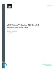
<strong>Trusted</strong> multi-tenancy foundational elements<br />
The trusted multi-tenancy solution comprises six foundational elements that address the unique<br />
requirements of the IaaS cloud service model:<br />
• Secure separation<br />
• Service assurance<br />
• Security and compliance<br />
• Availability and data protection<br />
• Tenant management and control<br />
• Service provider management and control<br />
Figure 1. Six elements of the <strong>Vblock</strong> <strong>Solution</strong> <strong>for</strong> <strong>Trusted</strong> <strong>Multi</strong>-<strong>Tenancy</strong><br />
© 2013 <strong>VCE</strong> Company, LLC. All Rights Reserved.<br />
9
Secure separation<br />
Secure separation refers to the effective segmentation and isolation of tenants and their assets within<br />
the multi-tenant environment. Adequate secure separation ensures that the resources of existing<br />
tenants remain untouched and the integrity of the applications, workloads, and data remains<br />
uncompromised when the service provider provisions new tenants. Each tenant might have access to<br />
different amounts of network, compute, and storage resources in the converged stack. The tenant<br />
sees only those resources allocated to them.<br />
From the standpoint of the service provider, secure separation requires the systematic deployment of<br />
various security control mechanisms throughout the infrastructure to ensure the confidentiality,<br />
integrity, and availability of tenant data, services, and applications. The logical segmentation and<br />
isolation of tenant assets and in<strong>for</strong>mation is essential <strong>for</strong> providing confidentiality in a multi-tenant<br />
environment. In fact, ensuring the privacy and security of each tenant becomes a key design<br />
requirement in the decision to adopt cloud services.<br />
Service assurance<br />
Service assurance plays a vital role in providing tenants with consistent, en<strong>for</strong>ceable, and reliable<br />
service levels. Unlike physical resources, virtual resources are highly scalable and easy to allocate<br />
and reallocate on demand. In a multi-tenant virtualized environment, the service provider prioritizes<br />
virtual resources to accommodate the growth and changing business needs of tenants. Service level<br />
agreements (SLA) define the level of service agreed to by the tenant and service provider. The<br />
service assurance element of trusted multi-tenancy provides technologies and methods to ensure that<br />
tenants receive the agreed-upon level of service.<br />
Various methods are available to deliver consistent SLAs across the network, compute, and storage<br />
components of the <strong>Vblock</strong> System, including:<br />
• Quality of service in the Cisco Unified Computing System (UCS) and Cisco Nexus plat<strong>for</strong>ms<br />
• EMC Symmetrix Quality of Service tools<br />
• EMC Unisphere Quality of Service Manager (UQM)<br />
• VMware Distributed Resource Scheduler (DRS)<br />
Without the correct mix of service assurance features and capabilities, it can be difficult to maintain<br />
uptime, throughput, quality of service, and availability SLAs.<br />
© 2013 <strong>VCE</strong> Company, LLC. All Rights Reserved.<br />
10
Security and compliance<br />
Security and compliance refers to the confidentiality, integrity, and availability of each tenant’s<br />
environment at every layer of the trusted multi-tenancy stack. <strong>Trusted</strong> multi-tenancy ensures security<br />
and compliance using technologies like identity management and access control, encryption and key<br />
management, firewalls, malware protection, and intrusion prevention. This is a primary concern <strong>for</strong><br />
both service provider and tenant.<br />
The trusted multi-tenancy solution ensures that all activities per<strong>for</strong>med in the provisioning,<br />
configuration, and management of the multi-tenant environment, as well as day-to-day activities and<br />
events <strong>for</strong> individual tenants, are verified and continuously monitored. It is also important that all<br />
operational events are recorded and that these records are available as evidence during audits.<br />
As regulatory requirements expand, the private cloud environment will become increasingly subject to<br />
security and compliance standards, such as Payment Card Industry Data Security Standards (PCI-<br />
DSS), HIPAA, Sarbanes-Oxley (SOX), and Gramm-Leach-Bliley Act (GLBA). With the proper tools,<br />
achieving and demonstrating compliance is not only possible, but it can often become easier than in a<br />
non-virtualized environment.<br />
Availability and data protection<br />
Resources and data must be available <strong>for</strong> use by the tenant. High availability means that resources<br />
such as network bandwidth, memory, CPU, or data storage are always online and available to users<br />
when needed. Redundant systems, configurations, and architecture can minimize or eliminate points<br />
of failure that adversely affect availability to the tenant.<br />
Data protection is a key ingredient in a resilient architecture. Cloud computing imposes a resource<br />
trade-off from high per<strong>for</strong>mance. Increasingly robust security and data classification requirements are<br />
an essential tool <strong>for</strong> balancing that equation. Enterprises need to know what data is important and<br />
where it is located as prerequisites to making per<strong>for</strong>mance cost-benefit decisions, as well as ensuring<br />
focus on the most critical areas <strong>for</strong> data loss prevention procedures.<br />
Tenant management and control<br />
In every cloud services model there are elements of control that the service provider delegates to the<br />
tenant. The tenant’s administrative, management, monitoring, and reporting capabilities need to be<br />
restricted to the delegated resources. Reasons <strong>for</strong> delegating control include convenience, new<br />
revenue opportunities, security, compliance, or tenant requirement. In all cases, the goal of the trusted<br />
multi-tenancy model is to allow <strong>for</strong> and simplify the management, visibility, and reporting of this<br />
delegation.<br />
© 2013 <strong>VCE</strong> Company, LLC. All Rights Reserved.<br />
11
Tenants should have control over relevant portions of their service. Specifically, tenants should be<br />
able to:<br />
• Provision allocated resources<br />
• Manage the state of all virtualized objects<br />
• View change management status <strong>for</strong> the infrastructure component<br />
• Add and remove administrative contacts<br />
• Request more services as needed<br />
In addition, tenants taking advantage of data protection or data backup services should be able to<br />
manage this capability on their own, including setting schedules and backup types, initiating jobs, and<br />
running reports.<br />
This tenant-in-control model allows tenants to dynamically change the environment to suit their<br />
workloads as resource requirements change.<br />
Service provider management and control<br />
Another goal of trusted multi-tenancy is to simplify management of resources at every level of the<br />
infrastructure and to provide the functionality to provision, monitor, troubleshoot, and charge back the<br />
resources used by tenants. Management of multi-tenant environments comes with challenges, from<br />
reporting and alerting to capacity management and tenant control delegation. The <strong>Vblock</strong> System<br />
helps address these challenges by providing scalable, integrated management solutions inherent to<br />
the infrastructure, and a rich, fully developed application programming interface (API) stack <strong>for</strong> adding<br />
additional service provider value.<br />
Providers of infrastructure services in a multi-tenant environment require comprehensive control and<br />
complete visibility of the shared infrastructure to provide the availability, data protection, security, and<br />
service levels expected by tenants. The ability to control, manage, and monitor resources at all levels<br />
of the infrastructure requires a dynamic, efficient, and flexible design that allows the service provider to<br />
access, provision, and then release computing resources from a shared pool – quickly, easily, and<br />
with minimal ef<strong>for</strong>t.<br />
© 2013 <strong>VCE</strong> Company, LLC. All Rights Reserved.<br />
12
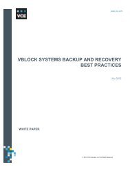
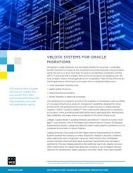
Technology overview<br />
The <strong>Vblock</strong> System from <strong>VCE</strong> is the world's most advanced converged infrastructure—one that<br />
optimizes infrastructure, lowers costs, secures the environment, simplifies management, speeds<br />
deployment, and promotes innovation. The <strong>Vblock</strong> System is designed as one architecture that spans<br />
the entire portfolio, includes best-in-class components, offers a single point of contact from initiation<br />
through support, and provides the industry's most robust range of configurations.<br />
Vbl ock Systems provide production ready (fully tested) virtualized infrastructure components, including<br />
industry-leading technologies from Cisco, EMC, and VMware. <strong>Vblock</strong> Systems are designed and built<br />
to satisfy a broad range of specific customer implementation requirements. To design trusted multitenancy,<br />
you need to understand each layer (compute, network, and storage) of the <strong>Vblock</strong> System<br />
architecture. Figure 2 provides an example of <strong>Vblock</strong> System architecture.<br />
Figure 2. Example of <strong>Vblock</strong> System architecture<br />
Note: Cisco Nexus 7000 is not part of the <strong>Vblock</strong> System architecture.<br />
This section describes the technologies at each layer of the <strong>Vblock</strong> System addressed in this guide to<br />
achieve trusted multi-tenancy.<br />
© 2013 <strong>VCE</strong> Company, LLC. All Rights Reserved.<br />
13
Management<br />
Management technologies include Advanced Management Pod (AMP) and EMC Ionix Unified<br />
Infrastructure Manager/Provisioning (UIM/P) (optional).<br />
Advanced Management Pod<br />
Vbl ock Systems include an AMP that provides a single management point <strong>for</strong> the <strong>Vblock</strong> System. It<br />
enables the following benefits:<br />
• Monitors and manages <strong>Vblock</strong> System health, per<strong>for</strong>mance, and capacity<br />
• Provides fault isolation <strong>for</strong> management<br />
• Eliminates resource overhead on the <strong>Vblock</strong> System<br />
• Provides a clear demarcation point <strong>for</strong> remote operations<br />
Two versions of the AMP are available: a mini-AMP and a high-availability version (HA AMP). A highavailability<br />
AMP is recommended.<br />
For more in<strong>for</strong>mation on AMP, refer to the Vbl ock Systems Architecture Overview documentation<br />
located at www.vce.com/vblock.<br />
EMC Ionix Unified Infrastructure Manager/Pr ovisioning<br />
EMC Ionix UIM/P can be used to provide automated provisioning capabilities <strong>for</strong> the <strong>Vblock</strong> System i n<br />
a trusted multi-tenancy environment by combining provisioning with configuration, change, and<br />
compliance management. With UIM/P, you can speed service delivery and reduce errors with policybased,<br />
automated converged infrastructure provisioning. Key features include the ability to:<br />
• Easily define and create infrastructure service profiles to match business requirements<br />
• Separate planning from execution to optimize senior IT technical staff<br />
• Respond to dynamic business needs with infrastructure service life cycle management<br />
• Maintain <strong>Vblock</strong> System compliance through policy-based management<br />
• Integrate with VMware vCenter and VMware vCloud Director <strong>for</strong> extended management<br />
capabilities<br />
© 2013 <strong>VCE</strong> Company, LLC. All Rights Reserved.<br />
14
Compute technologies<br />
Within the computing infrastructure of the <strong>Vblock</strong> System, multi-tenancy concerns at multiple levels<br />
must be addressed, including the UCS server infrastructure and the VMware vSphere Hypervisor.<br />
Cisco Unified Computing System<br />
The Cisco UCS is a next-generation data center plat<strong>for</strong>m that unites network, compute, storage, and<br />
virtualization into a cohesive system designed to reduce total cost of ownership and increase business<br />
agility. The system integrates a low-latency, lossless, 10 Gb Ethernet (GbE) unified network fabric with<br />
enterprise class x86 architecture servers. The system is an integrated, scalable, multi-chassis plat<strong>for</strong>m<br />
in which all resources participate in a unified management domain. Whether it has only one server or<br />
many servers with thousands of virtual machines (VM), the Cisco UCS is managed as a single<br />
system, thereby decoupling scale from complexity.<br />
Cisco UCS Manager provides unified, centralized, embedded management of all software and<br />
hardware components of the Cisco UCS across multiple chassis and thousands of virtual machines.<br />
The entire UCS is managed as a single logical entity through an intuitive graphical user interface<br />
(GUI), a command-line interface (CLI), or an XML API. UCS Manager delivers greater agility and<br />
scale <strong>for</strong> server operations while reducing complexity and risk. It provides flexible role- and policybased<br />
management using service profiles and templates, and it facilitates processes based on IT<br />
Infrastructure Library (ITIL) concepts.<br />
VMw are vSphere<br />
VMware vSphere is a complete, scalable, and powerful virtualization plat<strong>for</strong>m, delivering the<br />
infrastructure and application services that organizations need to trans<strong>for</strong>m their in<strong>for</strong>mation<br />
technology and deliver IT as a service. VMware vSphere is a host operating system that runs directly<br />
on the Cisco UCS infrastructure and fully virtualizes the underlying hardware, allowing multiple virtual<br />
machine guest operating systems to share the UCS physical resources.<br />
VMw are vCenter Server<br />
VMware vCenter Server is a simple and efficient way to manage VMware vSphere. It provides unified<br />
management of all the hosts and virtual machines in your data center from a single console with<br />
aggregate per<strong>for</strong>mance monitoring of clusters, hosts and virtual machines. VMware vCenter Server<br />
gives administrators deep insight into the status and configuration of clusters, hosts, virtual machines,<br />
storage, the guest operating system, and other critical components of a virtual infrastructure. It plays a<br />
key role in helping achieve secure separation, availability, tenant management and control, and<br />
service provider management and control.<br />
VMw are vCloud Director<br />
VMware vCloud Director gives customers the ability to build secure private clouds that dramatically<br />
increase data center efficiency and business agility. With VMware vSphere, VMware vCloud Director<br />
delivers cloud computing <strong>for</strong> existing data centers by pooling virtual infrastructure resources and<br />
delivering them to users as catalog-based services.<br />
© 2013 <strong>VCE</strong> Company, LLC. All Rights Reserved.<br />
15
VMw are vCenter Char geback<br />
VMware vCenter Chargeback is an end-to-end metering and cost reporting solution <strong>for</strong> virtual<br />
environments that enables accurate cost measurement, analysis, and reporting of virtual machines<br />
using VMware vSphere. Virtual machine resource consumption data is collected from VMware<br />
vCenter Server. Integration with VMware vCloud Director also enables automated chargeback <strong>for</strong><br />
private cloud environments.<br />
VMw are vShield<br />
The VMware vShield family of security solutions provides virtualization-aware protection <strong>for</strong> virtual<br />
data centers and cloud environments. VMware vShield products strengthen application and data<br />
security, enable trusted multi-tenancy, improve visibility and control, and accelerate IT compliance<br />
ef<strong>for</strong>ts across the organization.<br />
VMware vShield products include vShield App and vShield Edge. vShield App provides firewall<br />
capability between virtual machines by placing a firewall filter on every virtual network adapter. It<br />
allows <strong>for</strong> easy application of firewall policies. vShield Edge virtualizes data center perimeters and<br />
offers firewall, VPN, Web load balancer, NAT, and DCHP services.<br />
Storage technologies<br />
The features of multi-tenancy offerings can be combined with standard security methods such as<br />
storage area network (SAN) zoning and Ethernet virtual local area networks (VLAN) to segregate,<br />
control, and manage storage resources among the infrastructure tenants.<br />
EMC Fully Automated Storage Tiering<br />
EMC Fully Automated Storage Tiering (FAST) automates the movement and placement of data<br />
across storage resources as needed. FAST enables continuous optimization of your applications by<br />
eliminating trade-offs between capacity and per<strong>for</strong>mance, while simultaneously lowering cost and<br />
delivering higher service levels.<br />
EMC VNX FAS T VP<br />
EMC VNX FAST VP is a policy-based auto-tiering solution that efficiently utilizes storage tiers by<br />
moving slices of colder data to high-capacity disks. It increases per<strong>for</strong>mance by keeping hotter slices<br />
of data on per<strong>for</strong>mance drives.<br />
In a VMware vCloud environment, FAST VP enables providers to offer a blended storage offering,<br />
reducing the cost of a traditional single-type offering while allowing <strong>for</strong> a wider range of customer use<br />
cases. This helps accommodate a larger cross-section of virtual machines with different per<strong>for</strong>mance<br />
characteristics.<br />
© 2013 <strong>VCE</strong> Company, LLC. All Rights Reserved.<br />
16
EMC FA ST Cache<br />
EMC FAST Cache is an industry-leading feature supported by <strong>Vblock</strong> Systems. It extends the EMC<br />
VNX array’s read-write cache and ensures that unpredictable I/O spikes are serviced at enterprise<br />
flash drive (EFD) speeds, which is of particular benefit in a VMware vCloud Director environment.<br />
<strong>Multi</strong>ple virtual machines on multiple virtual machine file system (VMFS) data stores spread across<br />
multiple hosts can generate a very random I/O pattern, placing stress on both the storage processors<br />
as well as the DRAM cache. FAST Cache, a standard feature on all <strong>Vblock</strong> Systems, mitigates the<br />
effects of this kind of I/O by extending the DRAM cache <strong>for</strong> reads and writes, increasing the overall<br />
cache per<strong>for</strong>mance of the array, improving l/O during usage spikes, and dramatically reducing the<br />
overall number of dirty pages and cache misses.<br />
Because FAST Cache is aware of EFD disk tiers available in the array, FAST VP and FAST Cache<br />
work together to improve array per<strong>for</strong>mance. Data that has been promoted to an EFD tier is never<br />
cached inside FAST Cache, ensuring that both options are leveraged in the most efficient way.<br />
EMC Pow er Path/V E<br />
EMC PowerPath/VE delivers PowerPath multipathing features to optimize storage access in VMware<br />
vSphere virtual environments by removing the administrative overhead associated with load balancing<br />
and failover. Use PowerPath/VE to standardize path management across heterogeneous physical<br />
and virtual environments. PowerPath/VE enables you to automate optimal server, storage, and path<br />
utilization in a dynamic virtual environment.<br />
PowerPath/VE works with VMware vSphere ESXi as a multipathing plug-in that provides enhanced<br />
path management capabilities to ESXi hosts. It installs as a kernel module on the vSphere host and<br />
plugs in to the vSphere I/O stack framework to bring the advanced multipathing capabilities of<br />
PowerPath–dynamic load balancing and automatic failover–to the VMware vSphere plat<strong>for</strong>m.<br />
EMC Unified Storage<br />
The EMC Unified Storage system is a highly available architecture capable of five nines availability.<br />
The Unified Storage arrays achieve five nines availability by eliminating single points of failure<br />
throughout the physical storage stack, using technologies such as dual-ported drives, hot spares,<br />
redundant back-end loops, redundant front-end and back-end ports, dual storage processors,<br />
redundant fans and power supplies, and cache battery backup.<br />
EMC Unisphere Management Suite<br />
EMC Unisphere provides a simple, integrated experience <strong>for</strong> managing EMC Unified Storage through<br />
both a storage and VMware lens. Key features include a Web-based management interface to<br />
discover, monitor, and configure EMC Unified Storage; self-service support ecosystem to gain quick<br />
access to realtime online support tools; automatic event notification to proactively manage critical<br />
status changes; and customizable dashboard views and reporting.<br />
© 2013 <strong>VCE</strong> Company, LLC. All Rights Reserved.<br />
17
EMC Unisphere Quality of Service Manager<br />
EMC Unisphere Quality of Service (QoS) Manager enables dynamic allocation of storage resources to<br />
meet service level requirements <strong>for</strong> critical applications. QoS Manager monitors storage system<br />
per<strong>for</strong>mance on an appliance-by-application basis, providing a logical view of application per<strong>for</strong>mance<br />
on the storage system. In addition to displaying real-time data, per<strong>for</strong>mance data can be archived <strong>for</strong><br />
offline trending and data analysis.<br />
Network technologies<br />
<strong>Multi</strong>-tenancy concerns must be addressed at multiple levels within the network infrastructure of the<br />
Vbl ock System. Various methods, including zoning and VLANs, can en<strong>for</strong>ce network separation.<br />
Internet Protocol Security (IPsec) also provides application-independent network encryption at the IP<br />
layer <strong>for</strong> additional security.<br />
Cisco Nex us 1000V Series<br />
The Cisco Nexus 1000V is a software switch embedded in the software kernel of VMware vSphere.<br />
The Nexus 1000V provides virtual machine-level network visibility, isolation, and security <strong>for</strong> VMware<br />
server virtualization. With the Nexus 1000V Series, virtual machines can leverage the same network<br />
configuration, security policy, diagnostic tools, and operational models as their physical server<br />
counterparts attached to dedicated physical network ports. Virtualization administrators can access<br />
predefined network policies that follow mobile virtual machines to ensure proper connectivity, saving<br />
valuable resources <strong>for</strong> virtual machine administration.<br />
Cisco Nex us 5000 Series<br />
Cisco Nexus 5000 Series switches are data center class, high per<strong>for</strong>mance, standards-based<br />
Ethernet and Fibre Channel over Ethernet (FCoE) switches that enable the consolidation of LAN,<br />
SAN, and cluster network environments onto a single unified fabric.<br />
Cisco Nex us 7000 Series<br />
Cisco Nexus 7000 Series switches are modular switching systems designed <strong>for</strong> use in the data<br />
center. Nexus 7000 switches deliver the scalability, continuous systems operation, and transport<br />
flexibility required <strong>for</strong> 10 GB/s Ethernet networks today. In addition, the system architecture is capable<br />
of supporting future 40 GB/s Ethernet, 100 GB/s Ethernet, and unified I/O modules.<br />
Cisco MDS<br />
The Cisco MDS 9000 Series helps build highly available, scalable storage networks with advanced<br />
security and unified management. The Cisco MDS 9000 family facilitates secure separation at the<br />
network layer with virtual storage area networks (VSAN) and zoning. VSANs help achieve higher<br />
security and greater stability in fibre channel (FC) fabrics by providing isolation among devices that are<br />
physically connected to the same fabric. The zoning service within a fibre channel fabric provides<br />
security between devices sharing the same fabric.<br />
© 2013 <strong>VCE</strong> Company, LLC. All Rights Reserved.<br />
18
Cisco Data Center Netw ork Manager<br />
Cisco Data Center Network Manager provides an effective tool to manage the Cisco data center<br />
infrastructure and actively monitor the SAN and LAN.<br />
Security technologies<br />
RSA Archer eGRC and RSA enVision security technologies can be used to achieve security and<br />
compliance.<br />
RSA Archer eGRC<br />
The RSA Archer eGRC Plat<strong>for</strong>m <strong>for</strong> enterprise governance, risk, and compliance has the industry’s<br />
most comprehensive library of policies, control standards, procedures, and assessments mapped to<br />
current global regulations and industry guidelines. The flexibility of the RSA Archer framework,<br />
coupled with this library, provides the service providers and tenants in a trusted multi-tenant<br />
environment the mechanism to successfully implement a governance, risk, and compliance program<br />
over the <strong>Vblock</strong> System. This addresses both the components and technologies comprising the<br />
Vbl ock System and the virtualized services and resources i t hosts.<br />
Organizations can deploy the RSA Archer eGRC Plat<strong>for</strong>m in a variety of configurations, based on the<br />
expected user load, utilization, and availability requirements. As business needs evolve, the<br />
environment can adapt and scale to meet the new demands. Regardless of the size and solution<br />
architecture, the RSA Archer eGRC Plat<strong>for</strong>m consists of three logical layers: a .NET Web-enabled<br />
interface, the application layer, and a Microsoft SQL database backend.<br />
RSA enV ision<br />
The RSA enVision plat<strong>for</strong>m is a security in<strong>for</strong>mation and event management (SIEM) solution that<br />
offers a scalable, distributed architecture to collect, store, manage, and correlate event logs generated<br />
from all the components comprising the <strong>Vblock</strong> System–from the physical devices and software<br />
products to the management and orchestration and security solutions.<br />
By seamlessly integrating with RSA Archer eGRC, RSA enVision provides both service providers and<br />
tenants a powerful solution to collect and correlate raw data into actionable in<strong>for</strong>mation. Not only does<br />
RSA enVision satisfy regulatory compliance requirements, it helps ensure stability and integrity<br />
through robust incident management capabilities.<br />
© 2013 <strong>VCE</strong> Company, LLC. All Rights Reserved.<br />
19
<strong>Design</strong> framework<br />
This section provides the following in<strong>for</strong>mation:<br />
• End-to-end topology<br />
• Logical topology<br />
• Logical design details<br />
• Overview of tenant anatomy<br />
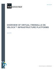
End-to-end topology<br />
Secure separation creates trusted zones that shield each tenant’s applications, virtual machines,<br />
compute, network, and storage from compromise and resource effects caused by adjacent tenants<br />
and external threats. The solution framework presented in this guide considers additional technologies<br />
that comprehensively provide appropriate in-depth defense. A combination of protective, detective,<br />
and reactive controls and solid operational processes are required to deliver protection against<br />
internal and external threats.<br />
Key layers include:<br />
• Virtual machine and cloud resources (VMware vSphere and VMware vCloud Director)<br />
• Virtual access/vSwitch (Cisco Nexus 1000V)<br />
• Storage and SAN (Cisco MDS and EMC storage)<br />
• Compute (Cisco UCS)<br />
• Access and aggregation (Nexus 5000 and Nexus 7000)<br />
Figure 3 illustrates the design framework.<br />
© 2013 <strong>VCE</strong> Company, LLC. All Rights Reserved.<br />
20
Figure 3. <strong>Trusted</strong> multi-tenancy design framework<br />
Virtual machine and c loud resources layer<br />
VMware vSphere and VMware vCloud Director are used in the cloud layer to accelerate the delivery<br />
and consumption of IT services while maintaining the security and control of the data center.<br />
VMware vCloud Director enables the consolidation of virtual infrastructure across multiple clusters, the<br />
encapsulation of application services as portable vApps, and the deployment of those services ondemand<br />
with isolation and control.<br />
© 2013 <strong>VCE</strong> Company, LLC. All Rights Reserved.<br />
21
Virtual access layer/v Sw itch<br />
Cisco Nexus 1000V distributed virtual switch acts as the virtual network access layer <strong>for</strong> the virtual<br />
machines. Edge LAN policies such as quality of service marking and vNIC ACLs are implemented at<br />
this layer in Nexus 1000V port-profiles.<br />
The following table describes the virtual access layer.<br />
Component<br />
One data center<br />
VMware ESXi serv ers<br />
Tenant<br />
Description<br />
One primary Nexus 1000V Virtual Superv isor Module (VSM)<br />
One secondary Nexus 1000V Virtual Superv isor Module<br />
Each running an instance of the Nexus 1000V Virtual Ethernet Module (VEM)<br />
<strong>Multi</strong>ple v irtual machines, which hav e diff erent applications such as Web<br />
serv er, database, and so f orth, <strong>for</strong> each tenant<br />
Storage and SA N layer<br />
The trusted multi-tenancy design framework is based on the use of storage arrays supporting fibre<br />
channel connectivity. The storage arrays connect through MDS SAN switches to the UCS 6120<br />
switches in the access layer. Several layers of security (including zoning, access controls at the guest<br />
operating system and ESXi level, and logical unit number (LUN) masking within the VNX) tightly<br />
control access to data on the storage system.<br />
Compute layer<br />
The following table provides an example of the components of a multi-tenant environment virtual<br />
compute farm.<br />
Note: A <strong>Vblock</strong> System may have more resources than what is described in the f ollowing table.<br />
Component<br />
Description<br />
Three UCS 5108 chassis • 11 UCS B200 servers (dual quad-core Intel Xeon X5570 CPU at<br />
2.93 GHZ and 96 GB RAM)<br />
• Four UCS B440 serv ers (f our Intel Xeon 7500 series processors<br />
and 32 dual in-line memory module slots with 256 GB memory)<br />
• Ten GbE Cisco VIC conv erged network adapters (CNA)<br />
organized into a VMware ESXi cluster<br />
15 serv ers (4 clusters) • Each serv er has two CNAs and are dual-attached to the UCS<br />
6100 f abric interconnect<br />
• The CNAs provide:<br />
- LAN and SAN connectivity to the serv ers, which run<br />
VMware ESXi 5.0 hypervisor<br />
- LAN and SAN services to the hypervisor<br />
© 2013 <strong>VCE</strong> Company, LLC. All Rights Reserved.<br />
22
Netw ork layers<br />
Access layer<br />
Nexus 5000 is used at the access layer and connects to the Cisco UCS 6120s. In the Layer 2 access<br />
layer, redundant pairs of Cisco UCS 6120 switches aggregate VLANs from the Nexus 1000V<br />
distributed virtual switch. FCoE SAN traffic from virtual machines is handed off as FC traffic to a pair of<br />
MDS SAN switches, and then to a pair of storage array controllers. FC expansion modules in the UCS<br />
6120 switch provide SAN interconnects to dual SAN fabrics. The UCS 6120 switches are in N Port<br />
virtualization (NPV) mode to interoperate with the SAN fabric.<br />
Aggrega tion la yer<br />
Nexus 7000 is used at the aggregation layer. The virtual device context (VDC) feature in the Nexus<br />
7000 separates it into sub-aggregation and aggregation virtual device contexts <strong>for</strong> Layer 3 routing.<br />
The aggregation virtual device context connects to the core network to route the internal data center<br />
traffic to the Internet and from the Internet back to the internal data center.<br />
Logical topology<br />
Figure 4 shows the logical topology <strong>for</strong> the trusted multi-tenancy design framework.<br />
© 2013 <strong>VCE</strong> Company, LLC. All Rights Reserved.<br />
23
Figure 4. <strong>Trusted</strong> multi-tenancy logical topology<br />
© 2013 <strong>VCE</strong> Company, LLC. All Rights Reserved.<br />
24
The logical topology represents the virtual components and virtual connections that exist within the<br />
physical topology. The following table describes the topology.<br />
Component<br />
Nexus 7000<br />
Nexus 5000<br />
Two UCS 6120 f abric<br />
interconnects<br />
Three UCS chassis<br />
UCS blade serv ers<br />
EMC VN X storage<br />
Details<br />
Virtualized aggregation lay er switch.<br />
Prov ides redundant paths to the Nexus 5000 access lay er. Virtual<br />
port channel prov ides a logically loopless topology with conv ergence<br />
times based on EtherChannel.<br />
Creates three v irtual dev ice contexts (VDC): WAN edge v irtual dev ice<br />
context, sub-aggregation v irtual dev ice context, and aggregation<br />
v irtual dev ice context. Sub-aggregation v irtual dev ice context<br />
connects to Nexus 5000 and aggregation v irtual dev ice context by<br />
v irtual port channel.<br />
Unif ied access lay er switch.<br />
Prov ides 10 GbE IP connectiv ity between the <strong>Vblock</strong> System and the<br />
outside world. In a unif ied storage conf iguration, the switches also<br />
connect the f abric interconnects in the compute lay er to the data<br />
mov ers in the storage lay er. The switches also prov ide connectiv ity to<br />
the AMP.<br />
Prov ides a robust compute lay er platf orm. Virtual port channel<br />
prov ides a topology with redundant chassis, cards, and links with<br />
Nexus 5000 and Nexus 7000.<br />
Each connects to one MDS 9148 to f orm its own f abric.<br />
Four 4 GB/s FC links connect the UCS 6120 to MDS 9148.<br />
The MDS 9148 switches connect to the storage controllers. In this<br />
example, the storage array has two controllers. Each MDS 9148 has<br />
two connections to each FC storage controller. These dual<br />
connections prov ide redundancy if an FC controller f ails and the MDS<br />
9148 is not isolated.<br />
Connect to the Nexus 5000 access switch through EtherChannel with<br />
dual-10 GbE.<br />
Each chassis is populated with blade serv ers and Fabric Extenders<br />
f or redundancy or aggregation of bandwidth.<br />
Connect to the SAN f abric through the Cisco UCS 6120XP f abric<br />
interconnect, which uses an 8-port 8 GB f ibre channel expansion<br />
module to access the SAN.<br />
Connect to LAN through the Cisco UCS 6120XP f abric interconnects.<br />
These ports require SFP+ adapters. The serv er ports of f abric<br />
interconnects can operate at 10 GB/s and Fibre Channel ports of<br />
f abric interconnects can operate at 2/4/8 GB/s.<br />
Connects to the f abric interconnect with 8 GB f ibre channel f or block.<br />
Connects to the Nexus 5000 access switch through EtherChannel<br />
with dual-10 GbE f or f ile.<br />
© 2013 <strong>VCE</strong> Company, LLC. All Rights Reserved.<br />
25
Tenant traffic flow representation<br />
Figure 5 depicts the traffic flow through each layer of the solution, from the virtual machine level to the<br />
storage layer.<br />
Figure 5. Tenant traffic flow<br />
© 2013 <strong>VCE</strong> Company, LLC. All Rights Reserved.<br />
26
Traffic flow in the data center is classified into the following categories:<br />
• Front-end—User to data center, Web, GUI<br />
• Back-end—Within data center, multi-tier application, storage, backup<br />
• Management—Virtual machine access, application administration, monitoring, and so <strong>for</strong>th<br />
Note: Front-end traffic, also called client-to-server traffic, trav erses the Nexus 7000 aggregation layer and a<br />
select number of network-based services.<br />
At the application layer, each tenant may have multiple vApps with applications and have different<br />
virtual machines <strong>for</strong> different workloads. The Cisco Nexus 1000V distributed virtual switch acts as the<br />
virtual access layer <strong>for</strong> the virtual machines. Edge LAN policies, such as quality of service marking<br />
and vNIC ACLs, can be implemented at the Nexus 1000V. Each ESXi server becomes a virtual<br />
Ethernet blade of Nexus 1000V, called Virtual Ethernet Module (VEM). Each vNIC connects to Nexus<br />
1000V through a port group; each port group specifies one or more VLANs used by a virtual machine<br />
NIC. The port group can also specify other network attributes, such as rate limit and port security. The<br />
VM uplink port profile <strong>for</strong>wards VLANs belonging to virtual machines. The system uplink port profile<br />
<strong>for</strong>wards VLANs belonging to management traffic. The virtual machine traffic <strong>for</strong> different tenants<br />
traverses the network through different uplink port profiles, where port security, rate limiting, and<br />
quality of service apply to guarantee secure separation and assurance.<br />
VMware vSphere virtual machine NICs are associated to the Cisco Nexus 1000V to be used as the<br />
uplinks. The network interface virtualization capabilities of the Cisco adapter enable the use of<br />
VMware multi-NIC design on a server that has two 10 GB physical interfaces with complete quality of<br />
service, bandwidth sharing, and VLAN portability among the virtual adapters. vShield Edge controls all<br />
network traffic to and from the virtual data center and helps provide an abstraction of the separation in<br />
the cloud environment.<br />
Virtual machine traffic goes through the UCS FEX (I/O module) to the fabric interconnect 6120.<br />
If the traffic is aligned to use the storage resources and it is intended to use FC storage, it passes over<br />
an FC port on the fabric interconnect and Cisco MDS, to the storage array, and through a storage<br />
processor, to reach the specific storage pool or storage groups. For example, if a tenant is using a<br />
dedicated storage resource with specific disks inside a storage array, traffic is routed to the assigned<br />
LUN with a dedicated storage group, RAID group, and disks. If there is NFS traffic, it passes over a<br />
network port on the fabric interconnect and Cisco Nexus 5000, through a virtual port channel to the<br />
storage array, and over a data mover, to reach the NFS data store. The NFS export LUN is tagged<br />
with a VLAN to ensure the security and isolation with a dedicated storage group, RAID group, and<br />
di sks. Figure 5 shows an example of a few dedicated tenant storage resources. However, if the<br />
storage is designed <strong>for</strong> a shared traffic pool, traffic is routed to a specific storage pool to pull<br />
resources.<br />
ESXi hosts <strong>for</strong> different tenants pass the server-client and management traffic over a server port and<br />
reach the access layer of the Nexus 5000 through virtual port channel.<br />
Server blades on UCS chassis are allocated <strong>for</strong> the different tenants. The resource on UCS can be<br />
dedicated or shared. For example, if using dedicated servers <strong>for</strong> each tenant, VLANs are assigned <strong>for</strong><br />
different tenants and are carried over the dot1Q trunk to the aggregation layer of the Nexus 7000,<br />
where each tenant is mapped to the Virtual Routing and Forwarding (VRF). Traffic is routed to the<br />
external network over the core.<br />
© 2013 <strong>VCE</strong> Company, LLC. All Rights Reserved.<br />
27
VMw are vSphere logical framew ork overview<br />
Figure 6 shows the virtual VMware vSphere layer on top of the physical server infrastructure.<br />
Figure 6. vSphere logical framework<br />
The diagram shows blade server technology with three chassis initially dedicated to the VMware<br />
vCloud environment. The physical design represents the networking and storage connectivity from the<br />
blade chassis to the fabric and SAN, as well as the physical networking infrastructure. (Connectivity<br />
between the blade servers and the chassis switching is different and is not shown here.) Two chassis<br />
are initially populated with eight blades each <strong>for</strong> the cloud resource clusters, with an even distribution<br />
between the two chassis of blades belonging to each resource cluster.<br />
In this scenario, VMware vSphere resources are organized and separated into management and<br />
resource clusters with three resource groups (Gold, Silver, and Bronze). Figure 7 illustrates the<br />
management cluster and resource groups.<br />
© 2013 <strong>VCE</strong> Company, LLC. All Rights Reserved.<br />
28
Figure 7. Management cluster and resource groups<br />
Cloud management clusters<br />
A cloud management cluster is a management cluster containing all core components and services<br />
needed to run the cloud. It is a resource group or “compute cluster” that represents dedicated<br />
resources <strong>for</strong> cloud consumption. It is best to use a separate cluster outside the <strong>Vblock</strong> System<br />
resources.<br />
Each resource group is a cluster of VMware ESXi hosts managed by a VMware vCenter Server, and<br />
is under the control of VMware vCloud Director. VMware vCloud Director can manage the resources<br />
of multiple resource groups or multiple compute clusters.<br />
Cloud management components<br />
The following components run as minimum-requirement virtual machines on the management cluster<br />
hosts:<br />
Components<br />
Number of virtual machines<br />
vCenter Serv er 1<br />
vCenter Database 1<br />
vCenter Update Manager 1<br />
vCenter Update Manager Database 1<br />
vCloud Director Cells<br />
2 (f or multi-cell)<br />
vCloud Director Database 1<br />
© 2013 <strong>VCE</strong> Company, LLC. All Rights Reserved.<br />
29
Components<br />
Number of virtual machines<br />
vCenter Chargeback Serv er 1<br />
vCenter Chargeback Database 1<br />
v Shield Manager 1<br />
Note: A vCloud Director cluster contains one or more vCloud Director serv ers; these servers are referred to as<br />
cells and f orm the basis of the VMware cloud. A cloud can be <strong>for</strong>med from multiple cells. The number of<br />
vCloud Director cells depends on the size of the vCloud environment and the level of redundancy.<br />
Figure 8 highlights the cloud management cluster.<br />
Figure 8. Cloud management cluster<br />
Resources allocated <strong>for</strong> cloud use have little overhead reserved. For example, cloud resource groups<br />
would not host vCenter management virtual machines. Best practices encourage separating the cloud<br />
management cluster from the cloud resource groups(s) in order to:<br />
• Facilitate quicker troubleshooting and problem resolution. Management components are strictly<br />
contained in a specified cluster and manageable management cluster.<br />
• Keep cloud management components separate from the resources they are managing.<br />
• Consistently and transparently manage and carve up resource groups.<br />
• Provide an additional step <strong>for</strong> high availability and redundancy <strong>for</strong> the trusted multi-tenancy<br />
infrastructure.<br />
© 2013 <strong>VCE</strong> Company, LLC. All Rights Reserved.<br />
30
Resource groups<br />
A resource group is a set of resources dedicated to user workloads and managed by VMware vCenter<br />
Server. vCloud Director manages the resources of all attached resource groups within vCenter<br />
Servers. All cloud-provisioning tasks are initiated through VMware vCloud Director and passed down<br />
to the appropriate vCenter Server instance.<br />
Figure 9 highlights cloud resource groups.<br />
Figure 9. Cloud resource groups<br />
Provisioning resources in standardized groupings promotes a consistent approach <strong>for</strong> scaling vCloud<br />
environments. For consistent workload experience, place each resource group on a separate<br />
resource cluster.<br />
The resource group design represents three VMware vSphere High Availability (HA) Distributed<br />
Resource Scheduler (DRS) clusters and infrastructure used to run the vApps that are provisioned and<br />
managed by VMware vCloud Director.<br />
© 2013 <strong>VCE</strong> Company, LLC. All Rights Reserved.<br />
31
Logical design<br />
This section provides in<strong>for</strong>mation about the logical design, including:<br />
• Cloud management cluster logical design<br />
• VMware vSphere cluster specifications<br />
• Host logical design specifications<br />
• Host logical configurations <strong>for</strong> resource groups<br />
• VMware vSphere cluster host design specifications <strong>for</strong> resource groups<br />
• Security<br />
Cloud management cluster logical des ign<br />
The compute design encompasses the VMware ESXi hosts contained in the management cluster.<br />
Specifications are listed below.<br />
Attribute<br />
Specification<br />
Number of ESXi hosts 3<br />
v Sphere datacenter 1<br />
VMware Distributed Resource Scheduler conf iguration<br />
VMware High Av ailability (HA) Enable Host Monitoring<br />
VMware High Av ailability Admission Control Policy<br />
Fully automated<br />
Yes<br />
Cluster tolerances 1 host f ailure (percentage<br />
based)<br />
VMware High Av ailability percentage 67%<br />
VMware High Av ailability Admission Control Response<br />
VMware High Av ailability Def ault VM Restart Priority<br />
VMware High Av ailability Host Isolation Response<br />
VMware High Av ailability Enable VM Monitoring<br />
VMware High Av ailability VM Monitoring Sensitiv ity<br />
Prev ent v irtual machines f rom being powered<br />
on if they violate av ailability constraints<br />
N/A<br />
Leav e v irtual machine powered on<br />
Yes<br />
Medium<br />
Note: In this section, the scope is limited to only the <strong>Vblock</strong> System supporting the management component<br />
workloads.<br />
© 2013 <strong>VCE</strong> Company, LLC. All Rights Reserved.<br />
32
vSpher e cluster specifications<br />
Each VMware ESXi host in the management cluster has the following specifications.<br />
Attribute<br />
Specification<br />
Host ty pe and v ersion VMware ESXi installable – v ersion 5.0<br />
Processors<br />
Storage presented<br />
Networking<br />
Memory<br />
x86 compatible<br />
SAN boot f or ESXi – 20 GB<br />
SAN LUN f or v irtual machines – 2 TB<br />
NFS shared LUN f or v Cloud Director cells – 1 TB<br />
Connectiv ity to all needed VLANs<br />
Size to support all management v irtual machines. In this case, 96 GB<br />
memory in each host.<br />
Note: VMware v Cloud Director deployment requires storage <strong>for</strong> sev eral elements of the ov erall framework. The<br />
first is the storage needed to house the vCloud Director management cluster. This includes the repository<br />
<strong>for</strong> configuration in<strong>for</strong>mation, organizations, and allocations that are stored in an Oracle database. The<br />
second is the vSphere storage objects presented to vCloud Director as data stores accessed by ESXi<br />
serv ers in the vCloud Director configuration. This storage is managed by the v Sphere administrator and<br />
consumed by vCloud Director users depending on vCloud Director configuration. The third is the existence<br />
of a single NFS data store to serv e as a staging area <strong>for</strong> vApps to be uploaded to a catalog.<br />
Host logical design specifications <strong>for</strong> cloud management c luster<br />
The following table identifies management components that rely on high availability and fault tolerance<br />
<strong>for</strong> redundancy.<br />
Management component<br />
vCenter Serv er<br />
vCloud Director<br />
vCenter Chargeback Serv er<br />
v Shield Manager<br />
High availability enabled<br />
Yes<br />
Yes<br />
Yes<br />
Yes<br />
© 2013 <strong>VCE</strong> Company, LLC. All Rights Reserved.<br />
33
Host logical configuration <strong>for</strong> resource groups<br />
The following table identifies the specifications <strong>for</strong> each VMware ESXi host in the resource cluster.<br />
Attribute<br />
Specification<br />
Host ty pe and v ersion VMware ESXi Installable – v ersion 5.0<br />
Processors<br />
Storage presented<br />
Networking<br />
Memory<br />
x86 compatible<br />
SAN boot f or ESXi – 20 GB<br />
SAN LUN f or v irtual machines – 2 TB<br />
Connectiv ity to all needed VLANs<br />
Size to support v irtual machine workloads<br />
VMw are vSphere cluster host des ign specification <strong>for</strong> resource groups<br />
All VMware vSphere resource clusters are configured similarly with the following specifications.<br />
Attribute<br />
VMware Distributed Resource Scheduler<br />
conf iguration<br />
VMware Distributed Resource Scheduler<br />
Migration Threshold<br />
VMware High Av ailability Enable Host<br />
Monitoring<br />
VMware High Av ailability Admission Control<br />
Policy<br />
Specification<br />
Fully automated<br />
3 stars<br />
Yes<br />
Cluster tolerances 1 host f ailure (percentage based)<br />
VMware High Av ailability percentage 83%<br />
VMware High Av ailability Admission Control<br />
Response<br />
VMware High Av ailability Default VM Restart<br />
Priority<br />
VMware High Av ailability Host Isolation<br />
Response<br />
Prev ent v irtual machines f rom being powered on if they<br />
v iolate av ailability constraints<br />
N/A<br />
Leav e v irtual machine powered on<br />
© 2013 <strong>VCE</strong> Company, LLC. All Rights Reserved.<br />
34
Security<br />
The RSA Archer eGRC Plat<strong>for</strong>m can be run on a single server, with the application and database<br />
components running on the same server. This configuration is suitable <strong>for</strong> organizations:<br />
• With fewer than 50 concurrent users<br />
• That do not require a high-per<strong>for</strong>mance or high availability solution<br />
For the trusted multi-tenancy framework, RSA enVision can be deployed as a virtual appliance in the<br />
AMP. Each <strong>Vblock</strong> System component can be configured to utilize it as its centralized event manager<br />
through its identified collection method. RSA enVision can then be integrated with RSA Archer eGRC<br />
per the RSA Security Incident Management <strong>Solution</strong> configuration guidelines.<br />
Tenant anatomy overview<br />
This design guide uses three tenants as examples: Orange (tenant 1), Vanilla (tenant 2), and Grape<br />
(tenant 3). All tenants share the same infrastructure and resources. Each tenant has its own virtual<br />
compute, network, and storage resources. Resources are allocated <strong>for</strong> each tenant based on their<br />
business model, requirements, and priorities. Traffic between tenants is restricted, separated, and<br />
protected <strong>for</strong> the trusted multi-tenancy environment.<br />
Figure 10. <strong>Trusted</strong> multi-tenancy tenant anatomy<br />
© 2013 <strong>VCE</strong> Company, LLC. All Rights Reserved.<br />
35
In this design guide (and associated configurations), three levels of services are provided in the cloud:<br />
Bronze, Silver, and Gold. These tiers define service levels <strong>for</strong> compute, storage, and network<br />
per<strong>for</strong>mance. The following table provides sample network and data differentiations by service tier.<br />
Bronze Silver Gold<br />
Serv ices No additional serv ices Firewall serv ices Firewall and loadbalancing<br />
serv ices<br />
Bandwidth 20% 30% 40%<br />
Segmentation<br />
One VLAN per client,<br />
single Virtual Routing<br />
and Forwarding (VRF)<br />
<strong>Multi</strong>ple VLANs per client,<br />
single VRF<br />
<strong>Multi</strong>ple VLANs per client,<br />
single VRF<br />
Data Protection None Snap – v irtual copy (local<br />
site)<br />
Disaster Recovery None Remote application (with<br />
specif ic recov ery point<br />
objectiv e (RPO) / recov ery<br />
time objectiv e (RTO))<br />
Clone – mirror copy (local<br />
site)<br />
Remote replication (any -<br />
point-in-time recov ery )<br />
Using this tiered model, you can do the following:<br />
• Offer service tiers with well-defined and distinct SLAs<br />
• Support customer segmentation based on desired service levels and functionality<br />
• Allow <strong>for</strong> differentiated application support based on service tiers<br />
© 2013 <strong>VCE</strong> Company, LLC. All Rights Reserved.<br />
36
<strong>Design</strong> considerations <strong>for</strong> management and orchestration<br />
Service providers can leverage Unified Infrastructure Manager/Provisioning to provision the <strong>Vblock</strong><br />
System in a trusted multi-tenancy environment. The AMP cluster of hosts holds UIM/P, which is<br />
accessed through a Web browser.<br />
Use UIM/P as a domain manager to provision <strong>Vblock</strong> Systems as a single entity. UIM/P interacts with<br />
the individual element managers <strong>for</strong> compute, storage, SAN, and virtualization to automate the most<br />
common and repetitive operational tasks required to provision services. It also interacts with VMware<br />
vCloud Director to automate cloud operations, such as the creation of a virtual data center.<br />
For provisioning, this guide focuses on the functional capabilities provided by UIM/P in a trusted multitenancy<br />
environment.<br />
As shown in Figure 11, the UIM/P dashboard gives service provider administrators a quick summary<br />
of available infrastructure resources. This eliminates the need to per<strong>for</strong>m manual discovery and<br />
documentation, thereby reducing the time it takes to begin deploying resources. Once administrators<br />
have resource availability in<strong>for</strong>mation, they can begin to provision existing service offerings or create<br />
new ones.<br />
Figure 11. UIM/P dashboard<br />
© 2013 <strong>VCE</strong> Company, LLC. All Rights Reserved.<br />
37
Figure 12. UIM/P service offerings<br />
© 2013 <strong>VCE</strong> Company, LLC. All Rights Reserved.<br />
38
Configuration<br />
While UIM/P automates the operational tasks involved in building services on <strong>Vblock</strong> Systems,<br />
administrators need to per<strong>for</strong>m initial task sets on each domain manager be<strong>for</strong>e beginning service<br />
provisioning. This section describes both key initial tasks to per<strong>for</strong>m on the individual domain<br />
managers and operational tasks managed through UIM/P.<br />
The following table shows what is configured as part of initial device configuration and what is<br />
configured through UIM/P.<br />
Device manager Initial configuration Operational configuration<br />
completed with UIM/P<br />
UCS Manager • Management conf iguration (IP and<br />
credentials<br />
• Chassis discov ery<br />
• Enable ports<br />
• KVMIP pool<br />
• Create VLANs<br />
• Assign VLANs<br />
• VSANs<br />
Unisphere MDS/Nexus • Management conf iguration (IP and<br />
credentials)<br />
• RAID group, storage pool, or both<br />
• Create LUNs<br />
• LAN<br />
• MAC pool<br />
• SAN<br />
• World Wide Name (WWN)<br />
pool<br />
• WWPN pool<br />
• Boot policies<br />
• Service templates<br />
• Select pools<br />
• Select boot policy<br />
• Serv er<br />
• UUID pool<br />
• Create service profile<br />
• Associate profile to server<br />
• Install v Sphere ESXi<br />
• Create storage group<br />
• Associate host and LUN<br />
• Zone<br />
• Aliases<br />
• Zone sets<br />
vCenter • Create Windows v irtual machine<br />
• Create database<br />
• Install vCenter software<br />
• Create data center<br />
• Create clusters<br />
• High availability policy<br />
• DRS policy<br />
• Distributed power<br />
management (DPM) policy<br />
• Add hosts to cluster<br />
• Create data stores<br />
• Create networks<br />
© 2013 <strong>VCE</strong> Company, LLC. All Rights Reserved.<br />
39
Enabling services<br />
After completing the initial configurations, use the following high-level workflow to enable services.<br />
Stage Workflow action Description<br />
1 <strong>Vblock</strong> System discovery Gather data f or <strong>Vblock</strong> Sy stem dev ices, interconnectiv ity, and<br />
external networks, and populate data in UIM database.<br />
2 Serv ice planning Collect serv ice resource requirements, including:<br />
• The number of servers and serv er attributes<br />
• Amount of boot and data storage and storage attributes<br />
• Networks to be used <strong>for</strong> connectivity between the service<br />
resources and external networks<br />
• vCenter Server and ESXi cluster in<strong>for</strong>mation<br />
3 Serv ice prov isioning Reserv e resources based on the serv er and storage<br />
requirements def ined f or the serv ice during serv ice planning.<br />
Install ESXi on the serv ers. Conf igure connectiv ity between the<br />
cluster and external networks.<br />
4 Serv ice activ ation Turn on the sy stem, start up Cisco UCS service profiles, activate<br />
network paths, and make resources av ailable f or use. The<br />
workf low separates prov isioning and activ ation, to allow<br />
activ ation of the serv ice as needed.<br />
5 vCenter sy nchronization Sy nchronize the ESXi clusters with the vCenter Serv er. Once<br />
y ou prov ision and activ ate a serv ice, the sy nchronizing process<br />
includes adding the ESXi cluster to the vCenter serv er data store<br />
and registering the cluster hosts prov isioned with v Center<br />
Serv er.<br />
6 vCloud sy nchronization Discov er vCloud and build a connection to the v Center serv ers.<br />
The clusters created in v Center Serv er are pushed to the<br />
appropriate vCloud. UIM/P integrates with vCloud Director in the<br />
same way it integrates with v Center Serv er.<br />
© 2013 <strong>VCE</strong> Company, LLC. All Rights Reserved.<br />
40
Figure 13 describes the provisioning, activation, and synchronization process, including key sub-steps<br />
during the provisioning process.<br />
Figure 13. Provisioning, activation, and synchronization process flow<br />
Creating a service offering<br />
To create a service offering:<br />
1. Select the operating system.<br />
2. Define server characteri sti cs.<br />
3. Define storage characteristics <strong>for</strong> startup.<br />
4. Define storage characteristics <strong>for</strong> application data.<br />
5. Create network profile.<br />
Pr ovisioning a service<br />
To provision a service:<br />
1. Select the service offering.<br />
2. Select <strong>Vblock</strong> System.<br />
3. Select servers.<br />
4. Configure IP and provide DNS hostname <strong>for</strong> operating system installation.<br />
5. Select storage.<br />
6. Select and configure network profile and vNICs.<br />
7. Configure vCenter cluster settings.<br />
8. Configure vCloud Director settings.<br />
© 2013 <strong>VCE</strong> Company, LLC. All Rights Reserved.<br />
41
<strong>Design</strong> considerations <strong>for</strong> compute<br />
Within the computing infrastructure of <strong>Vblock</strong> Systems, multi-tenancy concerns can be managed at<br />
multiple levels, from the central processing unit (CPU), through the Cisco Unified Computing System<br />
(UCS) server infrastructure, and within the VMware solution elements.<br />
This section describes the design of and rationale behind the trusted multi-tenancy framework. The<br />
design includes many issues that must be addressed prior to deployment, as no two environments are<br />
alike. <strong>Design</strong> considerations are provided <strong>for</strong> the components listed in the following table.<br />
Component Version Description<br />
Cisco UCS 2.0 Core component of the <strong>Vblock</strong> System that prov ides compute<br />
resources in the cloud. It helps achiev e secure separation,<br />
serv ice assurance, security , av ailability , and serv ice prov ider<br />
management in the trusted multi-tenancy f ramework.<br />
VMware v Sphere 5.0 Foundation of underly ing cloud inf rastructure and components.<br />
Includes:<br />
• VMware ESXi hosts<br />
• VMware v Center Serv er<br />
• Resource pools<br />
• VMware High Av ailability and Distributed Resource<br />
Scheduler<br />
• VMware v Motion<br />
VMware v Cloud Director 1.5 Builds on VMware v Sphere to prov ide a complete multi-tenant<br />
inf rastructure. It deliv ers on-demand cloud inf rastructure so<br />
users can consume v irtual resources with maximum agility. It<br />
consolidates data centers and deploys workloads on shared<br />
inf rastructure with built-in security and role-based access<br />
control. Includes:<br />
• VMware v Cloud Director Serv er (two instances, each<br />
installed on a Red Hat Linux virtual machine and ref erred to<br />
as a “cell”)<br />
• VMware v Cloud Director Database (one instance per<br />
clustered set of VMware vCloud Director cells)<br />
VMware v Shield 5.0 Prov ides network security serv ices, including NAT and f irewall.<br />
Includes:<br />
• v Shield Edge (deployed automatically on hosts as v irtual<br />
appliances by VMware v Cloud Director to separate tenants)<br />
• v Shield App (deployed on ESXi host layer to zone and<br />
secure virtual machine traffic)<br />
• v Shield Manager (one instance per vCenter Server in the<br />
cloud resource groups to manage vShield Edge and v Shield<br />
App)<br />
VMware v Center<br />
Chargeback<br />
1.6.2 Prov ides resource metering and chargeback models. Includes:<br />
• VMware v Center Chargeback Serv er<br />
• VMware Chargeback Data Collector<br />
• VMware v Cloud Data Collector<br />
• VMware v Shield Manager Data Collector<br />
© 2013 <strong>VCE</strong> Company, LLC. All Rights Reserved.<br />
42
<strong>Design</strong> considerations <strong>for</strong> secure separation<br />
This section discusses using the following technologies to achieve secure separation at the compute<br />
layer:<br />
• Cisco UCS<br />
• VMware vCloud Director<br />
Cisco UCS<br />
The UCS blade servers contain a pair of Cisco Virtual Interface Card (VIC) Ethernet uplinks. Cisco<br />
VIC presents virtual interfaces (UCS vNIC) to the VMware ESXi host, which allow <strong>for</strong> further traffic<br />
segmentation and categorization across all traffic types based on vNIC network policies.<br />
Using port aggregation between the fabric interconnect vNIC pairs enhances the availability and<br />
capacity of each traffic category. All inbound traffic is stripped of its VLAN header and switched to the<br />
appropriate destination’s virtual Ethernet interface. In addition, the Cisco VIC allows <strong>for</strong> the creation of<br />
multiple virtual host bus adapters (vHBA), permitting FC-enabled startup across the same physical<br />
infrastructure.<br />
Each VMware virtual interface type, VMkernel, and individual virtual machine interface connects<br />
directly to the Cisco Nexus 1000V software distributed virtual switch. At this layer, packets are tagged<br />
with the appropriate VLAN header and all outbound traffic is aggregated to the two Cisco fabric<br />
interconnects.<br />
This section contains in<strong>for</strong>mation about the high-level UCS features that help achieve secure<br />
separation in the trusted multi-tenancy framework:<br />
• UCS service profiles<br />
• UCS organizations<br />
• VLAN considerations<br />
• VSAN considerations<br />
UCS service profiles<br />
Use UCS service profiles to ensure secure separation at the compute layer. Hardware can be<br />
presented in a stateless manner that is completely transparent to the operating system and the<br />
applications that run on it. A service profile creates a hardware overlay that contains specific<br />
in<strong>for</strong>mation sensitive to the operating system:<br />
• MAC addresses<br />
• WWN values<br />
• UUID<br />
• BIOS<br />
• Firmware versions<br />
© 2013 <strong>VCE</strong> Company, LLC. All Rights Reserved.<br />
43
In a multi-tenant environment, the service provider can define a service profile giving access to any<br />
server in a predefined server resource with specific processor, memory, or other administrator-defined<br />
characteristics. The service provider can then provision one or more servers through service profiles,<br />
which can be used <strong>for</strong> an organization or a tenant. Service profiles are particularly useful when<br />
deployed with UCS Role-Based Access Control (RBAC), which provides granular administrative<br />
access control to UCS system resources based on administrative roles in a service provider<br />
environment.<br />
Servers instantiated by service profiles start up from a LUN that is tied to the specified WWPN,<br />
allowing an installed operating system instance to be locked with the service profile. The<br />
independence from server hardware allows installed systems to be re-deployed between blades.<br />
Through the use of pools and templates, UCS hardware can be quickly deployed and scaled.<br />
The trusted multi-tenancy framework uses three distinct server roles to segregate and classify UCS<br />
blade servers. This helps identify and associate specific service profiles depending on their purpose<br />
and policy. The following table describes these roles.<br />
Role<br />
Management<br />
Dedicated<br />
Mixed<br />
Description<br />
These serv ers can be associated with a serv ice prof ile that is meant only <strong>for</strong> cloud<br />
management or any type of serv ice prov ider inf rastructure workload.<br />
These serv ers can be associated with diff erent serv ice prof iles, serv er pools, and<br />
roles with VLAN policy ; f or example, <strong>for</strong> a specific tenant VLAN allowed access to<br />
those serv ers that are meant only <strong>for</strong> specif ic tenants.<br />
The trusted multi-tenancy f ramework considers a f ew tenants who strongly want to<br />
hav e a dedicated UCS cluster to f urther segregate workloads in the v irtualization<br />
lay er as needed. It also considers tenants who want dedicated workload throughput<br />
f rom the underly ing compute inf rastructure, which maps to the VMware Distributed<br />
Resource Scheduler cluster.<br />
These serv ers can be associated with a diff erent serv ice prof ile meant <strong>for</strong> shared<br />
resource clusters f or the VMware Distributed Resource Scheduler cluster.<br />
Depending on tenant requirements, UCS can be designed to use a dedicated<br />
compute resource or a shared resource. The trusted multi-tenancy framework uses<br />
mixed serv ers f or shared resource clusters as an example.<br />
These servers can be spread across the UCS fabric to minimize the impact of a single point of failure<br />
or a single chassis failure.<br />
© 2013 <strong>VCE</strong> Company, LLC. All Rights Reserved.<br />
44
Figure 14 shows an example of how the three servers are designed in the trusted multi-tenancy<br />
framework.<br />
Figure 14. <strong>Trusted</strong> multi-tenancy framework server design<br />
© 2013 <strong>VCE</strong> Company, LLC. All Rights Reserved.<br />
45
Figure 15 shows an example of three tenants (Orange, Vanilla, and Grape) using three service<br />
profiles on three different physical blades to ensure secure separation at the blade level.<br />
Figure 15. Secure separation at the blade level<br />
© 2013 <strong>VCE</strong> Company, LLC. All Rights Reserved.<br />
46
UCS organizations<br />
The Cisco UCS organizations feature helps with multi-tenancy by logically segmenting physical<br />
system resources. Organizations are logically isolated in the UCS fabric. UCS hardware and policies<br />
can be assigned to different organizations so that the appropriate tenant or organizational unit can<br />
access the assigned compute resources. A rich set of policies in UCS can be applied per organization<br />
to ensure that the right sets of attributes and I/O policies are assigned to the correct organization.<br />
Each organization can have its own pool of resources, including the following:<br />
• Resource pools (server, MAC, UUID, WWPN, and so <strong>for</strong>th)<br />
• Policies<br />
• Service profiles<br />
• Service profile templates<br />
UCS organizations are hierarchical. Root is the top-level organization. System-wi de policies and pools<br />
in root are available to all organizations in the system. Any policies and pools created in other<br />
organizations are available only to organizations below it in the same hierarchy.<br />
The functional isolation provided by UCS is helpful <strong>for</strong> a multi-tenant environment. Use the UCS<br />
features of RBAC and locales (a UCS feature to isolate tenant compute resources) on top of<br />
organizations to assign or restrict user privileges and roles by organization.<br />
Figure 16 shows the hierarchical organization of UCS clusters starting from Root. It shows three types<br />
of cluster configurations (Management, Dedicated, and Mixed). Below that are the three tenants<br />
(Orange, Vanilla, and Grape) with their service levels (Gold, Silver, and Bronze).<br />
Figure 16. UCS cluster hierarchical organization<br />
© 2013 <strong>VCE</strong> Company, LLC. All Rights Reserved.<br />
47
UCS allows the creation of resource pools to ensure secure separation between tenants. Use the<br />
following:<br />
• LAN resources<br />
• IP pool<br />
• MAC pool<br />
• VLAN pool<br />
• Management resources<br />
• KVM addresses pool<br />
• VLAN pool<br />
• SAN resources<br />
• WWN addresses pool<br />
• VSANs<br />
• Identity resources<br />
• UUID pool<br />
• Compute resources<br />
• Server pools<br />
Figure 17 illustrates how creating separate resource pools <strong>for</strong> the three tenants helps with secure<br />
separation at the compute layer.<br />
Figure 17. Resource pools<br />
© 2013 <strong>VCE</strong> Company, LLC. All Rights Reserved.<br />
48
Figure 18 is an example of a UCS Service Profile workflow diagram <strong>for</strong> three tenants.<br />
Figure 18. UCS service profile workflow<br />
VLAN considerations<br />
In Cisco UCS, a named VLAN creates a connection to a specific management LAN and tenantspecific<br />
VLANs. The VLAN isolates traffic, including broadcast traffic, to that external LAN. The name<br />
assigned to a VLAN ID adds a layer of abstraction that you can use to globally update all servers<br />
associated with service profiles using the named VLAN. You do not need to reconfigure servers<br />
individually to maintain communication with the external LAN. For example, if a service provider<br />
wanted to isolate a group of compute clusters <strong>for</strong> a specific tenant, the specific tenant VLAN needs to<br />
be allowed in the service profile of that tenant. This provides another layer of abstraction in secure<br />
separation.<br />
© 2013 <strong>VCE</strong> Company, LLC. All Rights Reserved.<br />
49
To illustrate, if Tenant Orange has dedicated UCS blades, it is recommended to allow only Tenant<br />
Orange-specific VLANs to ensure that only Tenant Orange has access to those blades. Figure 19<br />
shows a dedicated service profile <strong>for</strong> Tenant Orange that uses a vNIC template as Orange. Tenant<br />
Orange VLANs are allowed to use that specific vNIC template. However, a global vNIC template can<br />
still be used <strong>for</strong> all blades, providing the ability to allow or disallow specific VLANs from updating<br />
service profile templates.<br />
Figure 19. Dedicated service profile <strong>for</strong> Tenant Orange<br />
VSAN considerati ons in UCS<br />
A named VSAN creates a connection to a specific external SAN. The VSAN isolates traffic, including<br />
broadcast traffic, to that external SAN. The traffic on one named VSAN knows that the traffic on<br />
another named VSAN exists, but it cannot read or access that traffic.<br />
The name assigned to a VSAN ID adds a layer of abstraction that allows you to globally update all<br />
servers associated with service profiles that use the named VSAN. You do not need to individually<br />
reconfigure servers to maintain communication with the external SAN. You can create more than one<br />
named VSAN with the same VSAN ID.<br />
In a cluster configuration, a named VSAN is configured to be accessible to only the FC uplinks on<br />
both fabric interconnects.<br />
© 2013 <strong>VCE</strong> Company, LLC. All Rights Reserved.<br />
50
Figure 20 shows that VSAN 10 and VSAN 11 are configured in UCS SAN Cloud and uplinked to an<br />
FC port.<br />
Figure 20. VSAN configuration in UCS<br />
Figure 21 shows how an FC port is assigned to a VSAN ID in UCS. In this case, uplink FC Port 1 is<br />
assigned to VSAN10.<br />
Figure 21. Assigning a VSAN to FC ports<br />
© 2013 <strong>VCE</strong> Company, LLC. All Rights Reserved.<br />
51
VMw are vCloud Director<br />
VMware vCloud Director introduces logical constructs to facilitate multi-tenancy and provide<br />
interoperability between vCloud instances built to the vCloud API standard.<br />
VMware vCloud Director helps administer tenants—such as a business unit, organization, or<br />
di vi sion—by policy. In the trusted multi-tenancy framework, each organization has isolated virtual<br />
resources, independent LDAP-based authentication, specific policy controls, and unique catalogs. To<br />
ensure secure separation in a trusted multi-tenancy environment where multiple organizations share<br />
Vbl ock System resources, the framework includes VMware vCloud Director along with VMware<br />
vShield perimeter protection, port-level firewall, and NAT and DHCP services.<br />
Figure 22 shows a logical separation of organizations in VMware vCloud Director.<br />
Figure 22. Organization separation<br />
© 2013 <strong>VCE</strong> Company, LLC. All Rights Reserved.<br />
52
A service provider may want to view all the listed tenants or organizations in vCloud Director to easily<br />
manage them. Figure 23 shows the service provider’s tenant view in VMware vCloud Director.<br />
Figure 23. Tenant view in vCloud Director<br />
Organizations are the unit of multi-tenancy within vCloud Director. They represent a single logical<br />
security boundary. Each organization contains a collection of users, computing resources, catalogs,<br />
and vApp workloads. Organization users can be local users or imported from an LDAP server. LDAP<br />
integration can be specific to an organization, or it can leverage an organizational unit within the<br />
system LDAP configuration, as defined by the vCloud system administrator. The name of the<br />
organization, specified during creation time, maps to a unique URL that allows access to the GUI <strong>for</strong><br />
that organization. For example, Figure 24 shows that Tenant Orange maps to a specific default<br />
organization URL. Each tenant accesses the resource using its own URL and authentication.<br />
Figure 24. Organization unique identifier URL<br />
© 2013 <strong>VCE</strong> Company, LLC. All Rights Reserved.<br />
53
The vCloud Director network provides an extra layer of separation. vCloud Director has three different<br />
types of networking, each with a specific purpose:<br />
• External network<br />
• Organization network<br />
• vApp network<br />
External netw ork<br />
The external network is the connection to the outside world. An external network always needs a port<br />
group, meaning that a port group needs to be available within VMware vSphere and the distributed<br />
switch.<br />
Tenants commonly require direct connections from inside the vCloud environment into the service<br />
provider networking backbone. This is analogous to extending a wire from the network switch<br />
containing the network or VLAN to be used, all the way through the vCloud layers into the vApp. Each<br />
organization in the trusted multi-tenancy environment has an internal organization network and a<br />
direct connect external organization network.<br />
Organization network<br />
An organization network provides network connectivity to vApp workloads within an organization.<br />
Users in an organization have no visibility into external networks and connect to outside networks<br />
through external organization networks. This is analogous to users in an organization connecting to a<br />
corporate network that is uplinked to a service provider <strong>for</strong> Internet access.<br />
The following table lists connectivity options <strong>for</strong> organization networks.<br />
Network type<br />
External organization<br />
External organization<br />
Internal organization<br />
Connectivity<br />
Direct connection<br />
NAT/routed<br />
Isolated<br />
A directly connected external organization network places the vApp virtual machines in the port group<br />
of the external network. IP address assignments <strong>for</strong> vApps follow the external network IP addressing.<br />
Internal and routed external organization networks are instantiated through network pools by vCloud<br />
sy stem administrators. Organization administrators do not have the ability to provision organization<br />
networks but can configure network services such as firewall, NAT, DHCP, VPN, and static routing.<br />
Note: Organization network is meant only <strong>for</strong> the intra-organization network and is specific to an organization.<br />
© 2013 <strong>VCE</strong> Company, LLC. All Rights Reserved.<br />
54
Figure 25 shows an example of an internal and external network configuration.<br />
Figure 25. Internal and external organization networks<br />
Servi ce providers provision organization networks using network pools. Figure 26 shows the service<br />
provider’s administrator view of the organization networks.<br />
Figure 26. Administrator view of organization networks<br />
© 2013 <strong>VCE</strong> Company, LLC. All Rights Reserved.<br />
55
v App netw ork<br />
A vApp network is similar to an organization network. It is meant <strong>for</strong> a vApp internal network. It acts as<br />
a boundary <strong>for</strong> isolating specific virtual machines within a vApp. A vApp network is an isolated<br />
segment created <strong>for</strong> a particular application stack within an organization’s network to enable multi-tier<br />
applications to communicate with each other and, at the same time, isolate the intra-vApp traffic from<br />
other applications within the organization. The resources to create the isolation are managed by the<br />
organization administrator and allocated from a pool provided by the vCloud administrator.<br />
Figure 27 shows a vApp configuration <strong>for</strong> Tenant Grape.<br />
Figure 27. Micro-segmentation of virtual workloads<br />
Network pools<br />
All three network classes can be backed using the virtual network features of the Nexus 1000V. It is<br />
important to understand the relationship between the virtual networking features of the Nexus 1000V<br />
and the classes of networks defined and implemented in a vCloud Director environment. Typically, a<br />
network class (specifically, an organization and vApp) is described as being backed by an allocation of<br />
isolated networks. For an organization administrator to create an isolated vApp network, the<br />
administrator must have a free isolation resource to consume and use in order to provide that isolated<br />
network <strong>for</strong> the vApp.<br />
© 2013 <strong>VCE</strong> Company, LLC. All Rights Reserved.<br />
56
To deploy an organization or vApp network, you need a network pool in vCloud Director. Network<br />
pools contain network definitions used to instantiate private/routed organization and vApp networks.<br />
Networks created from network pools are isolated at Layer 2. You can create three types of network<br />
pools in vCloud Director, as shown in the following table.<br />
Network Pool Type<br />
v Sphere port group backed<br />
VLAN backed<br />
vCloud Director network<br />
isolation backed<br />
Description<br />
Network pools are backed by pre-prov isioned port groups in Cisco Nexus<br />
1000V or VMware distributed switch.<br />
A range of pre-prov isioned VLAN IDs back network pools. This assumes<br />
all VLANs specif ied are trunked.<br />
Network pools are backed by v Cloud isolated networks, which are an<br />
ov erlay network uniquely identif ied by a f ence ID implemented through<br />
encapsulation techniques that span hosts and prov ide traffic isolation f rom<br />
other networks. It requires a distributed switch. vCloud Director creates<br />
port groups automatically on distributed switches as needed.<br />
Figure 28 shows how network pool types are presented in VMware vCloud Director.<br />
Figure 28. Network pools<br />
© 2013 <strong>VCE</strong> Company, LLC. All Rights Reserved.<br />
57
Each pool has specific requirements, limitations, and recommendations. The trusted multi-tenancy<br />
framework uses a port group backed network pool with a Cisco Nexus 1000V Distributed switch. Each<br />
port group is isolated to its own VLAN ID. Each tenant (network, in this case) is associated with its<br />
own network pool, each backed by a set of port groups.<br />
VMware vCloud Director automatically deploys vShield Edge devices to facilitate routed network<br />
connections. vShield Edge uses MAC encapsulation <strong>for</strong> NAT routing, which helps prevent Layer 2<br />
network in<strong>for</strong>mation from being seen by other organizations in the environment. vShield Edge al so<br />
provides a firewall service that can be configured to block inbound traffic to virtual machines<br />
connected to a public access organization network.<br />
<strong>Design</strong> considerations <strong>for</strong> service assurance<br />
This section discusses using the following technologies to achieve service assurance at the compute<br />
layer:<br />
• Cisco UCS<br />
• VMware vCloud Director<br />
Cisco UCS<br />
The following UCS features support service assurance:<br />
• Quality of service<br />
• Port channels<br />
• Server pools<br />
• Redundant UCS fabrics<br />
Compute, storage, and network resources need to be categorized in order to provide a differential<br />
service model <strong>for</strong> a multi-tenant environment. The following table shows an example of Gold, Silver,<br />
and Bronze service levels <strong>for</strong> compute resources.<br />
Level<br />
Gold<br />
Silv er<br />
Bronze<br />
Compute resource<br />
UCS B440 blades<br />
UCS B200 and B440 blades<br />
UCS B200 blades<br />
System classes in the UCS specify the bandwidth allocated <strong>for</strong> traffic types across the entire system.<br />
Each system class reserves a specific segment of the bandwidth <strong>for</strong> a specific type of traffic. Using<br />
quality of service policies, the UCS assigns a system class to the outgoing traffic and then matches a<br />
quality of service policy to the class of service (CoS) value marked by the Nexus 1000V Series switch<br />
<strong>for</strong> each virtual machine.<br />
UCS quality of service configuration can help achieve service assurance <strong>for</strong> multiple tenants. A best<br />
practice to ensure guaranteed quality of service throughout a multi-tenant environment is to configure<br />
quality of service <strong>for</strong> different service levels on the UCS.<br />
© 2013 <strong>VCE</strong> Company, LLC. All Rights Reserved.<br />
58
Figure 29 shows different quality of service weight values configured <strong>for</strong> different class of service<br />
values that correspond to Gold, Silver, and Bronze service levels. This helps ensure traffic priority <strong>for</strong><br />
tenants associated with those service levels.<br />
Figure 29. Quality of service configuration<br />
Quality of service policies assign a system class to the outgoing traffic <strong>for</strong> a vNIC or vHBA. There<strong>for</strong>e,<br />
to configure the vNIC or vHBA, include a quality of service policy in a vNIC or vHBA policy and then<br />
include that policy in a service profile. Figure 30 shows how to create quality of service polici es.<br />
Figure 30. Creating quality of service policy<br />
© 2013 <strong>VCE</strong> Company, LLC. All Rights Reserved.<br />
59
VMw are vCloud Director<br />
VMware vCloud Director provides several allocation models to achieve service levels in the trusted<br />
multi-tenancy framework. An organization virtual data center allocates resources from a provider<br />
virtual data center and makes them available <strong>for</strong> use by a given organization. <strong>Multi</strong>ple organization<br />
virtual data centers can take from the same provider virtual data center. One organization can have<br />
multiple organization virtual data centers.<br />
Resources are taken from a provider virtual data center and allocated to an organization virtual data<br />
center using one of three resource allocation models, as shown in the following table.<br />
Model<br />
Pay as y ou go<br />
Allocation<br />
Reserv ation<br />
Description<br />
Resources are reserv ed and committed <strong>for</strong> v Apps only as v Apps are created.<br />
There is no upf ront reserv ation of resources.<br />
A baseline amount (guarantee) of resources f rom the prov ider v irtual data<br />
center is reserv ed f or the organization v irtual data center’s exclusiv e use. An<br />
additional percentage of resources are av ailable to ov ersubscribe CPU and<br />
memory, but this taps into compute resources that are shared by other<br />
organization v irtual data centers drawing f rom the prov ider v irtual data center.<br />
All resources assigned to the organization v irtual data center are reserv ed<br />
exclusiv ely f or the organization v irtual data center’s use.<br />
With all the above models, the organization can be set to deploy an unlimited or limited number of<br />
virtual machines. In selecting the appropriate allocation model, consider the service definition and<br />
organization’s use case workloads.<br />
Although all tenants use the shared infrastructure, the resources <strong>for</strong> each tenant are guaranteed<br />
based on the allocation model in place. The service provider can set the parameters <strong>for</strong> CPU,<br />
memory, storage, and network <strong>for</strong> each tenant’s organization virtual data center, as shown in Figure<br />
31, Figure 32, and Figure 33.<br />
© 2013 <strong>VCE</strong> Company, LLC. All Rights Reserved.<br />
60
Figure 31. Organization virtual data center allocation configuration<br />
Figure 32. Organization virtual data center storage allocation<br />
© 2013 <strong>VCE</strong> Company, LLC. All Rights Reserved.<br />
61
Figure 33. Organization virtual data center network pool allocation<br />
<strong>Design</strong> considerations <strong>for</strong> security and compliance<br />
This section discusses using the following technologies to achieve security and compliance at the<br />
compute layer:<br />
• Cisco UCS<br />
• VMware vCloud Director<br />
• VMware vCenter Server<br />
Cisco UCS<br />
The UCS Role-Based Access Control (RBAC) feature helps ensure security by providing granular<br />
administrative access control to the UCS system resources based on administrative roles, tenant<br />
organization, and locale.<br />
The RBAC function of the Cisco UCS allows you to control service provider user access to the actions<br />
and resources in the UCS. RBAC is a security mechanism that can greatly lower the cost and<br />
complexity of <strong>Vblock</strong> System security administration. RBAC simplifies security administration by using<br />
roles, hierarchies, and constraints to organize privileges. Cisco UCS Manager offers flexible RBAC to<br />
define the roles and privileges <strong>for</strong> different administrators within the Cisco UCS environment.<br />
The UCS RBAC allows access to be controlled based on the roles assigned to individuals. The<br />
following table lists the elements of the UCS RBAC model.<br />
© 2013 <strong>VCE</strong> Company, LLC. All Rights Reserved.<br />
62
Element<br />
Role<br />
User<br />
Action<br />
Priv ilege<br />
Locale<br />
Description<br />
A job f unction within the context of locale, along with the authority and<br />
responsibility giv en to the user assigned to the role<br />
A person using the UCS; users are assigned to one or more roles<br />
Any task a user can perf orm in the UCS that is subject to access control; an<br />
action is perf ormed on a resource<br />
Permission granted or denied to a role to perf orm an action<br />
A logical object created to manage organizations and determine which users<br />
hav e priv ileges to use the resources in organizations<br />
The UCS RBAC feature can help service providers segregate roles to manage multiple tenants. One<br />
example is using UCS RBAC with LDAP integration to ensure all roles are defined and have specific<br />
accesses as per their roles. A service provider can leverage this feature in a multi-tenant environment<br />
to ensure a high level of centralized security control. LDAP groups can be created <strong>for</strong> different<br />
administration roles, such as network, storage, server profiles, security, and operations. This helps<br />
providers keep security and compliance in place by having designated roles to configure different<br />
parts of the <strong>Vblock</strong> System.<br />
Figure 34 shows an LDAP group mapped to a specific role in a UCS. An Active Directory group called<br />
ucsnetw ork is mapped to a predefined network role in UCS. This means that anyone belonging to<br />
the ucsnetwork group in Active Directory can per<strong>for</strong>m a network task in UCS; other features are<br />
shown as read-onl y.<br />
Figure 34. LDAP group mapping in UCS<br />
© 2013 <strong>VCE</strong> Company, LLC. All Rights Reserved.<br />
63
Figure 35 illustrates how UCS groups provide hierarchy. It shows how group ucsnetw ork is laid out in<br />
an Active Directory domain.<br />
Figure 35. Active Directory groups <strong>for</strong> UCS LDAP<br />
Additional UCS security control features i ncl ude the following:<br />
• Administrative access to the Cisco UCS is authenticated by using either:<br />
- A remote protocol such as LDAP, RADIUS, or TACACS+<br />
- A combination of local database and remote protocols<br />
• HTTPS provides authenticated and encrypted access to the Cisco UCS Manager GUI. HTTPS<br />
uses components of the Public Key Infrastructure (PKI), such as digital certificates, to establish<br />
secure communications between the client’s browser and Cisco UCS Manager.<br />
© 2013 <strong>VCE</strong> Company, LLC. All Rights Reserved.<br />
64
VMw are vCloud Director<br />
Role-based and centralized user authentication through multi-party Active Directory/LDAP integration<br />
is the best way to manage the cloud. In VMware vCloud Director, each organization represents a<br />
collection of end users, groups, and computing resources. Users authenticate at the organization<br />
level, using credentials validated through LDAP. Set this up based on the cloud organization’s<br />
requirements.<br />
For example, Service Provider–<strong>VCE</strong> can have its own Active Directory infrastructure <strong>for</strong> user and<br />
groups to authenticate to the vCloud environment. Tenant Orange can have its own Active Directory<br />
to manage authentication to the vCloud environment. Having each organization with their own Active<br />
Directory improves security by providing ease of integration with organization identity and access<br />
management processes and controls, and it ensures that only authorized users have access to the<br />
tenant cloud infrastructure. Figure 36 and Figure 37 show both the service provider and organization<br />
LDAP integration and the difference in LDAP server settings.<br />
Figure 36. Service provider LDAP integration<br />
© 2013 <strong>VCE</strong> Company, LLC. All Rights Reserved.<br />
65
Figure 37. Organization LDAP integration<br />
Each tenant has its own user and group management and provides role-based security access, as<br />
shown in Figure 38. The users are shown only the vApps that they can access. vApps that users do<br />
not have access to are not visible, even if they reside within the same organization.<br />
Figure 38. User role management<br />
© 2013 <strong>VCE</strong> Company, LLC. All Rights Reserved.<br />
66
VMw are vCenter Server<br />
VMware vCenter Server is installed using a local administrator account. When vCenter Server is<br />
joined to a domain, it results in any domain administrator gaining administrative privileges to vCenter.<br />
To remove this potential security risk, it is recommended to always create a vCenter Administrator<br />
group in an Active Directory and assign it to the vCenter Server Administrator role, making it possible<br />
to remove the local administrators group from this role.<br />
Note: Refer to the vSphere Security Hardening <strong>Guide</strong> at www.vmware.com <strong>for</strong> more inf ormation.<br />
In Figure 39, in the trusted multi-tenancy framework there is a VMw are Admins group created in an<br />
Active Directory. This group has access to the trusted multi-tenancy vCenter data center. A user<br />
member of this group can per<strong>for</strong>m the administration of vCenter.<br />
Figure 39. vCenter administration<br />
<strong>Design</strong> considerations <strong>for</strong> availability and data protection<br />
Availability and Disaster Recovery (DR) focuses on the recovery of systems and infrastructure after an<br />
incident interrupts normal operations. A disaster can be defined as partial or complete unavailability of<br />
resources and services, including applications, the virtualization layer, the cloud layer, or the<br />
workloads running in the resource groups.<br />
Good practices at the infrastructure level will lead to easier disaster recovery of the cloud<br />
management cluster. This includes technologies such as high availability, DRS, and vMotion <strong>for</strong><br />
reactive and proactive protection of your infrastructure.<br />
This section discusses using the following technologies to achieve availability and data protection at<br />
the compute layer:<br />
• Cisco UCS<br />
• Virtualization<br />
© 2013 <strong>VCE</strong> Company, LLC. All Rights Reserved.<br />
67
Cisco UCS<br />
Fabric interconnect clustering allows each fabric interconnect to continuously monitor the other’s<br />
status. If one fabric interconnect becomes unavailable, the other takes over automatically.<br />
Figure 40 shows how Cisco UCS is deployed as a high availability cluster <strong>for</strong> management layer<br />
redundancy. It is configured as two Cisco UCS 6100 Series fabric interconnects directly connected<br />
with Ethernet cables between the L1 (L1-to-L1) and L2 (L2-to-L2) ports.<br />
Figure 40. Fabric interconnect clustering<br />
Service profile dynamic mobility provides another layer of protection. When a physical blade server<br />
fails, it automatically transfers the service profile to an available server in the pool.<br />
Virtual port channel in UCS<br />
With virtual port channel uplinks, there is minimal impact of both physical link failures and upstream<br />
switch failures. With more physical member links in one larger logical uplink, there is the potential <strong>for</strong><br />
even better overall uplink load balancing and better high availability.<br />
© 2013 <strong>VCE</strong> Company, LLC. All Rights Reserved.<br />
68
Figure 41 shows how port channel 101 and 102 are configured with four uplink members.<br />
Figure 41. Virtual port channel in UCS<br />
Virtualization<br />
Enable overall cloud availability design <strong>for</strong> tenants using the following features:<br />
• VMware vSphere HA<br />
• VMware vCenter Heartbeat<br />
• VMware vMoti on<br />
• VMware vCloud Director cells<br />
VMware vSphere High Availability<br />
VMware High Availability clusters enable a collection of VMware ESXi hosts to work together to<br />
provide, as a group, higher levels of availability <strong>for</strong> virtual machines than each ESXi host could provide<br />
individually. When planning the creation and use of a new VMware High Availability cluster, the<br />
options you select affect how that cluster responds to failures of hosts or virtual machines.<br />
VMware High Availability provides high availability <strong>for</strong> virtual machines by pooling the machines and<br />
the hosts on which they reside into a cluster. Hosts in the cluster are monitored and in the event of a<br />
failure, the virtual machines on the failed host are restarted on alternate hosts.<br />
© 2013 <strong>VCE</strong> Company, LLC. All Rights Reserved.<br />
69
In the trusted multi-tenancy framework, all VMware High Availability clusters are deployed with<br />
identical server hardware. Using identical hardware provides a number of key advantages, including<br />
the following:<br />
• Simplified configuration and management of the servers using host profiles<br />
• Increased ability to handle server failures and reduced resource fragmentation<br />
VMw are v Motion<br />
VMware vMotion enables the live migration of running virtual machines from one physical server to<br />
another with zero downtime, continuous service availability, and complete transaction integrity. Use<br />
VMware vMotion to:<br />
• Per<strong>for</strong>m hardware maintenance without scheduled downtime<br />
• Proactively migrate virtual machines away from failing or underper<strong>for</strong>ming servers<br />
• Automatically optimize and allocate entire pools of resources <strong>for</strong> optimal hardware utilization and<br />
alignment with business priorities<br />
VMware vCenter Heartbeat<br />
Use VMware vCenter Heartbeat to protect vCenter Server in order to provide an additional layer of<br />
resiliency. The vCenter Heartbeat server works by replicating all vCenter configuration and data to a<br />
secondary passive server using a dedicated network channel. The secondary server is up all the time,<br />
with the live configuration of the active server, but an IP packet filter masks it from the active network.<br />
Figure 42 shows a scenario when the complete hardware goes down, the operating system crashes,<br />
or the active vCenter link is down.<br />
Figure 42. vCenter Heartbeat scenario<br />
© 2013 <strong>VCE</strong> Company, LLC. All Rights Reserved.<br />
70
VMware v Cloud Director cells<br />
VMware vCloud Director cells are stateless front-end processors <strong>for</strong> the vCloud. Each cell has a<br />
variety of purposes and self-manages various functions among cells while connecting to a central<br />
database. The cell manages connectivity to the cloud and provides both API and GUI endpoi<br />
nts/clients.<br />
Figure 43 shows the trusted multi-tenancy framework using multiple cells (a load-balanced group) to<br />
address availability and scale. This is typically achieved by load balancing or content switching this<br />
front-end layer. Load balancers present a consistent address <strong>for</strong> services regardless of the underlying<br />
node responding. They can spread session load across cells, monitor cell health, and add or remove<br />
cells from the active service pool.<br />
Figure 43. vCloud Director multi-cell<br />
© 2013 <strong>VCE</strong> Company, LLC. All Rights Reserved.<br />
71
Single point of failure<br />
To ensure successful implementation of availability, which is a crucial part of the trusted multi-tenancy<br />
design, carefully consider each component listed in the following table.<br />
Component<br />
ESXi hosts<br />
ESXi host network connectiv ity<br />
ESXi host storage connectiv ity<br />
vCenter Serv er<br />
vCenter database<br />
v Shield Manager<br />
vCenter Chargeback<br />
vCloud Director<br />
Availability options<br />
Conf igure all VMware ESXi hosts in highly av ailable clusters with a<br />
minimum of n+1 redundancy . This prov ides protection not only f or the<br />
v irtual machines, but also f or the v irtual machines hosting the platf orm<br />
portal/management applications and all of the v Shield Edge appliances.<br />
Conf igure the ESXi host with a minimum of two phy sical paths to each<br />
required net work (port group) to ensure that a single link f ailure does<br />
not impact platf orm or v irtual machine connectivity. This should include<br />
management and v Motion networks. The Load Based Teaming<br />
mechanism is used to av oid ov ersubscribed network links.<br />
Conf igure ESXi hosts with a minimum of two phy sical paths to each<br />
LUN or NFS share to ensure that a single storage path f ailure does not<br />
impact service.<br />
Run v Center Serv er as a virtual machine and make use of v Center<br />
Serv er Heartbeat.<br />
vCenter Heartbeat prov ides v Center database resiliency.<br />
v Shield Manager receiv es the additional protection of VMware FT,<br />
resulting in seamless f ailov er between hosts in the ev ent of a host<br />
f ailure<br />
Deploy vCenter Chargeback v irtual machines as a two-node, loadbalanced<br />
cluster. Deploy multiple Chargeback data collectors remotely<br />
to av oid a single point of failure.<br />
Deploy the v Cloud Director virtual machines as a load-balanced, highly<br />
av ailable clustered pair in an N+1 redundancy setup, with the option to<br />
scale out when the env ironment requires this.<br />
VMware Site Recovery Manager<br />
In addition to other components, you can use VMware Site Recovery Manager (SRM) <strong>for</strong> disaster<br />
recovery and availability. Site Recovery Manager accelerates recovery by automating the recovery<br />
process, and it simplifies the management of disaster recovery plans by making disaster recovery an<br />
integrated element of the management of your VMware virtual infrastructure. VMware Site Recovery<br />
Manager is fully supported on the <strong>Vblock</strong> System; however, it is not supported with VMware vCloud<br />
Director and is not within the scope of this design guide.<br />
© 2013 <strong>VCE</strong> Company, LLC. All Rights Reserved.<br />
72
<strong>Design</strong> considerations <strong>for</strong> tenant management and control<br />
This section discusses using VMware vCloud Director to achieve tenant management and control at<br />
the compute layer.<br />
VMw are vCloud Director<br />
VMware vCl oud Director provides an intuitive Web portal (vCloud Self Service Portal) that<br />
organization users use to manage their compute, storage, and network resources. In general, a<br />
dedicated group of users in a tenant manages the organization resources, such as creating or<br />
assigning networks and catalogs and allocating memory, CPU, or storage resources to an<br />
organization.<br />
In Figure 44, the tenants can create the vApps or deploy them from templates. Tenants can create the<br />
vApp network as needed from the network pool; use the browser plug-in to upload media and access<br />
the console of the virtual machines in the vApp; and start and stop the virtual machines as needed.<br />
For example, when Tenant Orange wants to access its virtual environment, it needs to point to the<br />
URL https://vcd1.pluto.vcelab.net/cloud/org/orange.<br />
Figure 44. vApp administration<br />
© 2013 <strong>VCE</strong> Company, LLC. All Rights Reserved.<br />
73
Te nant in-control configuration<br />
The tenants can manage users and groups, policies, and the catalogs <strong>for</strong> their environment, as shown<br />
in Figure 45.<br />
Figure 45. Environment administration<br />
<strong>Design</strong> considerations <strong>for</strong> service provider management and control<br />
This section discusses using virtualization technologies to achieve service provider management and<br />
control at the compute layer.<br />
Virtualization<br />
A service provider will have access to the entire VMware vSphere and VMware vCloud environment<br />
to flexibly manage and monitor the environment. A service provider can access and manage the<br />
following:<br />
• vCenter with a virtual infrastructure (VI) client<br />
• Cisco UCS<br />
• vCloud with a Web browser pointing to the vCloud Director cell address<br />
• vShield Manager with a Web browser pointing to the IP or hostname<br />
• vCenter Chargeback with a Web browser pointing to the IP or hostname<br />
• Cisco Nexus 1000V with SSH to Virtual Supervisor Module<br />
© 2013 <strong>VCE</strong> Company, LLC. All Rights Reserved.<br />
74
For example, in vCloud Director, the service provider is in complete control of the physical<br />
infrastructure. The service provider can:<br />
• Enable or disable ESXi hosts and data stores <strong>for</strong> cloud usage<br />
• Create and remove the external networks that are needed <strong>for</strong> communicating with the Internet,<br />
backup networks, IP-based storage networks, VPNs, and MPLS networks, as well as the<br />
organization networks and network pools<br />
• Create and remove the organization, administration users, provider virtual data center, and<br />
organization virtual data centers<br />
• Determine which organization can share the catalog with others<br />
Figure 46 shows how a service provider views the complete physical infrastructure in vCloud Director.<br />
Figure 46. Service provider view<br />
VMware vCenter Chargeback<br />
VMware vCenter Chargeback is an end-to-end metering and cost reporting solution <strong>for</strong> virtual<br />
environments using VMware vSphere. It has the following core components:<br />
• Data Collectors:<br />
- Chargeback Data Collector—responsible <strong>for</strong> vCenter Server data collection<br />
- vCloud Director (vCD) and vShield Manager (vSM) data collectors — responsible <strong>for</strong><br />
utilization/allocation collection on the new abstraction layer created by vCloud Director<br />
• Load Balancer (embedded in vCenter Chargeback) — receives and routes all user requests to<br />
the application; needs to be installed only once <strong>for</strong> the Chargeback cluster<br />
• Chargeback Server and chargeback database<br />
© 2013 <strong>VCE</strong> Company, LLC. All Rights Reserved.<br />
75
Figure 47 shows a <strong>Vblock</strong> System chargeback deployment architecture model.<br />
Figure 47. <strong>Vblock</strong> System chargeback deploy ment architecture<br />
© 2013 <strong>VCE</strong> Company, LLC. All Rights Reserved.<br />
76
Key <strong>Vblock</strong> System metrics<br />
When determining a metering methodology <strong>for</strong> trusted multi-tenancy, consider the following:<br />
• What metrics (units, components, or attributes) will be monitored<br />
• How will the metrics be obtained<br />
• What sampling frequency will be used <strong>for</strong> each metric<br />
• How will the metrics be aggregated and correlated to <strong>for</strong>mulate meaningful business value<br />
Within a <strong>Vblock</strong> System virtualized computing environment, the infrastructure chargeback details can<br />
be modeled as fully loaded measurements per virtual machine. The virtual machine essentially<br />
becomes the point resource allocated back to users/customers. Below are the some of the key<br />
metrics to collect when measuring virtual machine resource utilization:<br />
Resource Chargeback metrics Unit of measurement<br />
CPU CPU usage GHz<br />
Virtual CPU (v CPU)<br />
Count<br />
Memory Memory usage GB<br />
Memory size<br />
GB<br />
Network Network receiv ed/transmitted usage GB<br />
Disk Storage usage GB<br />
Disk read/write usage<br />
GB<br />
For more in<strong>for</strong>mation, see <strong>Guide</strong>lines <strong>for</strong> Metering and Chargeback Using VMware vCenter<br />
Chargeback on www.vce.com.<br />
© 2013 <strong>VCE</strong> Company, LLC. All Rights Reserved.<br />
77
<strong>Design</strong> considerations <strong>for</strong> storage<br />
<strong>Multi</strong>-tenancy features can be combined with standard security methods, such as storage area<br />
network (SAN) zoning and Ethernet VLANs, to segregate, control, and manage storage resources<br />
among the infrastructure’s tenants. <strong>Multi</strong>-tenancy offerings include data-at-rest encryption; secure<br />
transmission of data; and bandwidth, cache, CPU, and disk drive isolation.<br />
This section describes the design of and rationale behind storage technologies in the trusted multitenancy<br />
framework. The design includes many issues that must be addressed prior to deployment.<br />
<strong>Design</strong> considerations <strong>for</strong> secure separation<br />
The fundamental principle that makes multi-tenancy secure is that no tenant can access another’s<br />
data. Secure separation is essential to reaching this goal. At the storage layer, secure separation can<br />
be divided into the following basic requirements:<br />
• Segmentation of path by VSAN and zoning<br />
• Separation of data at rest<br />
• Address space separation<br />
• Separation of data access<br />
Segmentation by VSA N and zoning<br />
To extend secure separation to the storage layer, consider the isolation mechanisms available in a<br />
SAN environment.<br />
Cisco MDS storage area networks (SAN) offer true segmentation mechanisms, similar to VLANs in<br />
Ethernet. These mechanisms, called VSANs, work with fibre channel zones; however, VSANs do not<br />
tie into the virtual host bus adapter (HBA) of a virtual machine. VSANs and zones associate to a host<br />
rather than a virtual machine. All virtual machines running on a particular host belong to the same<br />
VSAN or zone. Since it is not possible to extend SAN isolation to the virtual machine, VSANs or FC<br />
zones are used to isolate hosts from each other in the SAN fabric.<br />
To keep management overhead low, we do not recommend deploying a large number of VSANs.<br />
Instead, the trusted multi-tenancy design leverages fibre channel soft zone configuration to isolate the<br />
storage layer on a per-host basis. It combines this method with zoning through WWN/device alias <strong>for</strong><br />
administrative flexibility.<br />
Fibre channel zones<br />
SAN zoning can restrict visibility and connectivity between devices connected to a common fibre<br />
channel SAN. It is a built-in security mechanism available in an FC switch that prevents traffic leaking<br />
between zones.<br />
© 2013 <strong>VCE</strong> Company, LLC. All Rights Reserved.<br />
78
<strong>Design</strong> scenarios of VSAN and zoning<br />
VSANs and zoning are two powerful tools within the Cisco MDS 9000 family of products that aid the<br />
cloud administrator in building robust, secure, and manageable storage networking environments<br />
while optimizing the use and cost of storage switching hardware. In general, VSANs are used to divide<br />
a redundant physical SAN infrastructure into separate virtual SAN islands, each with its own set of<br />
fibre channel fabric services. Having each VSAN support an independent set of fibre channel services<br />
enables a VSAN-enabled infrastructure to house numerous applications without ri sk of fabric resource<br />
or event conflicts between the virtual environments. Once the physical fabric is divided, use zoning to<br />
implement a security layout that is tuned to the needs of each application within each VSAN. Figure<br />
48 illustrates the VSAN physical topology.<br />
Figure 48. VSAN physical topology<br />
© 2013 <strong>VCE</strong> Company, LLC. All Rights Reserved.<br />
79
VSANs are first created as isolated fabrics within a common physical topology. Once VSANs are<br />
created, apply individual unique zone sets as necessary within each VSAN. The following table<br />
summarizes the primary differences between VSANs and zones.<br />
Characteristic VS AN s Zoning<br />
Maximum per switch/fabric 1024 per switch 1000+ zones per f abric (VSAN)<br />
Membership criteria Phy sical port Physical port, WWN<br />
Isolation enf orcement method Hardware Hardware<br />
Fibre channel serv ice model New set of serv ices per VSAN Same set of serv ices <strong>for</strong> entire<br />
f abric<br />
Traff ic isolation method Hardware-based tagging Implicit using hardware ACLs<br />
Traff ic accounting Yes per VSAN No<br />
Separate manageability Yes per VSAN (f uture) No<br />
Traff ic engineering Yes per VSAN No<br />
Note: Note that UIM supports only one VSAN f or each fabric.<br />
Separation of data at rest<br />
Today, most deployments treat physical storage as a shared infrastructure. However, in multi-tenancy,<br />
it is sometimes necessary to ensure that a specific dataset does not share spindles with any other<br />
dataset. This separation could be required between tenants or even within a single tenant’s dataset.<br />
Business reasons <strong>for</strong> this include competitive companies using the same shared service, and<br />
governance/regulatory requirements.<br />
EMC VNX provides flexible RAID and volume configurations that allow spindles to be dedicated to<br />
LUNs or storage pools. VNX allows the creation of tenant-specific storage pools that can be used to<br />
dedicate specified spindles to particular tenants.<br />
Address space separation<br />
In some situations, each tenant is completely unaware of the other tenants. However, without proper<br />
mitigation there is the potential <strong>for</strong> address space overlap. Fibre channel World Wide Names (WWN)<br />
and iSCSI device names are globally unique, with no possibility of contention in either area. IP<br />
addresses, however, are not globally unique and may conflict.<br />
To remedy this situation, the service provider can assign infrastructure-wide IP addresses within a<br />
service offering. Each X-Blade or VNX storage processor supports one IP address space. However,<br />
an X-Blade can support multiple logical IP interfaces and both storage processors and X-Blades<br />
support VLAN tagging. VLAN tagging allows multiple networks to access resources without the risk of<br />
traversing address spaces. In the event of an IP address conflict, the server log file reports any<br />
duplicate address warnings. IP addressing conflicts can be addressed in higher layers of the stack.<br />
This is most easily accomplished at the compute layer.<br />
© 2013 <strong>VCE</strong> Company, LLC. All Rights Reserved.<br />
80
Figure 49 is a graphical representation of how VM ware vSphere can be used to separate each<br />
tenant’s address space.<br />
Figure 49. Address space separation with VMware vSphere<br />
© 2013 <strong>VCE</strong> Company, LLC. All Rights Reserved.<br />
81
Virtual machine data store separation<br />
VMware uses a cluster file system called a virtual machine file system (VMFS). An ESXi host<br />
associates a VMFS volume, which is made up of a larger logical unit. Each virtual machine directory is<br />
stored in the Virtual Machine Disk (VMDK) sub-directory in the VMFS volume. While a virtual machine<br />
is in operation, the VMFS volume locks those files to prevent other ESXi servers from updating them.<br />
One VMDK directory is associated with a single virtual machine; multiple virtual machines cannot<br />
access the same VMDK directory.<br />
We recommend implementing LUN masking (that is, storage groups) to assign storage to ESXi<br />
servers. LUN masking is an authorization process that makes a LUN available only to specific hosts<br />
on the EMC SAN as further protection against misbehaving servers corrupting disks belonging to<br />
other servers. This complements the use of zoning on the MDS, effectively extending zoning from the<br />
front-end port on the array to the device on which the physical disk resides.<br />
Virtual data mov er on VNX<br />
VNX provides a multinaming domain solution <strong>for</strong> a data mover in the UNIX environment by<br />
implementing an NFS server per virtual data mover (VDM). A data mover hosting several VDMs can<br />
serve UNIX clients that are members of different LDAP or NIS domains, assuming that each VDM<br />
works <strong>for</strong> a unique naming domain. Several NFS servers are emulated on the data mover in order to<br />
serve the file system resources of the data mover <strong>for</strong> different naming domains. Each NFS server is<br />
assigned to one or more data mover network interfaces.<br />
The VDMs loaded on a data mover use the network interfaces configured on the data mover. You<br />
cannot duplicate an IP address <strong>for</strong> two VDM interfaces configured on the same data mover. Once a<br />
VDM interface is assigned, you can manage NFS exports on a VDM. CIFS and NFS protocols can<br />
share the same network interface; however, only one NFS endpoint and CIFS server is addressed<br />
through a particular logical network interface.<br />
The multinaming domain solution implements an NFS server per VDM-named NFS endpoint. The<br />
VDM acts as a container that includes the file systems exported by the NFS endpoint and/or the CIFS<br />
server. These VDM file systems are visible through a subset of data mover network interfaces<br />
attached to the VDM. The same network interface can be shared by both CIFS and NFS protocols on<br />
that VDM. The NFS endpoint and CIFS server are addressed through the network interfaces attached<br />
to that particular VDM. This allows users to per<strong>for</strong>m either of the following:<br />
• Move a VDM, along with its NFS and CIFS exports and configuration data (LDAP, net groups,<br />
and so <strong>for</strong>th), to another data mover<br />
• Back up the VDM, along with its NFS and CIFS exports and configuration data<br />
This feature supports at least 50 NFS VDMs per physical data mover and up to 25 LDAP domains.<br />
© 2013 <strong>VCE</strong> Company, LLC. All Rights Reserved.<br />
82
Figure 50 shows a physical data mover with VDM implementation.<br />
Figure 50. Physical data mover with VDM implementation<br />
Note: VDM f or NFS is available on VNX OE <strong>for</strong> File Version 7.0.50.2. You cannot use Unisphere to configure<br />
VDM f or NFS.<br />
Refer to Configuring Virtual Data Movers on VNX <strong>for</strong> more in<strong>for</strong>mation (Powerlink access required).<br />
Separation of data access<br />
Separation of data access ensures that a tenant cannot see or access any other tenant’s data. The<br />
data access protocol in use determines how this is accomplished. Protocols <strong>for</strong> how tenant data traffic<br />
flows inside EMC VNX are:<br />
• CIFS<br />
• NFS<br />
• iSCSI<br />
• Fibre Channel over Ethernet/Fibre Channel (FCoE/FC)<br />
© 2013 <strong>VCE</strong> Company, LLC. All Rights Reserved.<br />
83
Figure 51 displays the access protocols and the respective protocol stack that can be used to access<br />
data residing on a unified system.<br />
Figure 51. Protocol stack<br />
CIFS stack<br />
The following table summarizes how tenant data traffic flows inside EMC VNX <strong>for</strong> the CIFS stack.<br />
Secure separation is maintained at each layer throughout the CIFS stack.<br />
CIFS stack component<br />
VLAN<br />
IP Interf ace VLAN Tagged<br />
IP Packet Reflection<br />
Virtual Data Mov er<br />
CIFS Server<br />
Description<br />
The secure separation of data access starts at the bottom of the CIFS<br />
stack on the IP network with the use of Virtual Local Area Networks<br />
(VLAN) to separate indiv idual tenants.<br />
The VLAN-tagging model extends into the unif ied system by VLAN<br />
tagging the indiv idual IP interf aces so they understand and honor the<br />
tags being used.<br />
IP packet ref lection guarantees that any traff ic sent from the storage<br />
sy stem in response to a client request will go out ov er the same phy sical<br />
connection and VLAN on which the request was receiv ed.<br />
The v irtual data mov er is a logical conf iguration container that wraps<br />
around a CIFS f ile-sharing instance.<br />
The v irtual data mov er resides on the CIFS serv er.<br />
© 2013 <strong>VCE</strong> Company, LLC. All Rights Reserved.<br />
84
CIFS stack component<br />
CIFS Share<br />
ABE<br />
Description<br />
CIFS shares are built upon the CIFS serv ers.<br />
At the top of the stack is a Windows f eature called Access Based<br />
Enumeration (ABE). ABE shows a user only the f iles that he/she has<br />
permission to access, thus extending the separation all the way to end<br />
users if desired.<br />
NFS stack<br />
The following table summarizes how tenant data traffic flows inside EMC VNX <strong>for</strong> the NFS stack.<br />
NFS stack component<br />
VLAN<br />
IP Interf ace VLAN tagged<br />
IP packet ref lection<br />
NFS export VLAN tagged<br />
NFS export hiding<br />
Description<br />
The secure separation of data access starts at the bottom of the NFS<br />
stack on the IP network, using VLANs to separate indiv idual tenants.<br />
The VLAN tagging model extends into the unif ied system by VLAN<br />
tagging the indiv idual IP interf aces so they understand and honor the<br />
tags being used.<br />
IP packet ref lection guarantees that any traff ic sent from the storage<br />
sy stem in response to a client request will go out ov er the same phy sical<br />
connection and VLAN on which the request was receiv ed.<br />
NFS exports can be associated with specif ic VLANs.<br />
NFS export hiding tightly controls which users access the NFS exports. It<br />
enhances standard NFS serv er behav ior by prev enting users f rom<br />
seeing NFS exports f or which they do not hav e access-lev el permission.<br />
It will appear to each tenant that they hav e their own indiv idual NFS<br />
serv er.<br />
© 2013 <strong>VCE</strong> Company, LLC. All Rights Reserved.<br />
85
Figure 52 shows an NFS export and how a specific subnet has access to the NFS share.<br />
Figure 52. NFS export configuration<br />
In this example, VLAN 112 and VLAN 111 subnet has access to the /nfs1 share. VNX also provides<br />
granular access to the NFS share. An NFS export can be presented to a specific tenant subnet or<br />
specific host or group of hosts in the network.<br />
iSCSI stack<br />
The following table summarizes how tenant data traffic flows inside EMC VNX <strong>for</strong> the iSCSI stack.<br />
iSCSI stack component<br />
VLAN<br />
IP Interf ace VLAN tagged<br />
iSCSI Portal<br />
Target<br />
LUN<br />
LUN Masking<br />
Description<br />
The secure separation of data access starts at the bottom of the iSCSI<br />
stack on the IP network with the use of VLAN to separate indiv idual<br />
tenants.<br />
The VLAN-tagging model extends into the unif ied system by VLAN<br />
tagging the indiv idual IP interf aces so they understand and honor the<br />
tags being used.<br />
Access then f lows through an iSCSI portal to a target dev ice, where it is<br />
ultimately addressed to a LUN.<br />
LUN masking is a f eature f or block-based protocols that ensures that<br />
LUNs are v iewed and accessed only by those SAN clients with the<br />
appropriate permissions.<br />
© 2013 <strong>VCE</strong> Company, LLC. All Rights Reserved.<br />
86
Support <strong>for</strong> VLAN tagging in iSCSI<br />
VLAN is supported <strong>for</strong> iSCSI data ports and management ports on VNX storage systems. In addition<br />
to better per<strong>for</strong>mance, ease of management, and cost benefits, VLANs provide security advantages<br />
since devices configured with VLAN tags can see and communicate with each other only if they<br />
belong to the same VLAN. There<strong>for</strong>e, you can:<br />
• Set up multiple virtual ports on the VNX and segregate hosts into different VLANs based on your<br />
security policy<br />
• Restrict sensitive data to one VLAN<br />
VLANs make it more difficult to sniff traffic, as they require sniffing across multiple networks. This<br />
provides extra security.<br />
Figure 53 shows the iSCSI port properties <strong>for</strong> a port with VLANs enabled and two virtual ports<br />
configured.<br />
Figure 53. iSCSI Port Properties with VLAN tagging enabled<br />
© 2013 <strong>VCE</strong> Company, LLC. All Rights Reserved.<br />
87
Fibre Channel ov er Ethernet/fibre channel stack<br />
The lower layers of the fibre channel stack look quite different because it is not an IP-based protocol.<br />
The following table summarizes how tenant data traffic flows inside EMC VNX <strong>for</strong> the FCoE/FC stack.<br />
FCoE/FC stack component<br />
FC Zone<br />
VSAN<br />
Target<br />
LUN<br />
LUN Masking<br />
Description<br />
FC zoning controls which FC/Fibre Channel ov er Ethernet (FCoE)<br />
interf aces can communicate with each other within the f abric.<br />
Virtual Storage Area Networks can be used to f urther subdiv ide<br />
indiv idual zones without the need f or phy sical separation.<br />
Access flows to a target dev ice, where it is ultimately addressed to a<br />
LUN.<br />
LUN masking is a f eature f or block-based protocols that ensures that<br />
LUNs are v iewed and accessed only by those SAN clients with the<br />
appropriate permissions.<br />
Figure 54 and Figure 55 show how a 20 GB FC boot LUN and 2 TB LUN map to each host in VNX. It<br />
ensures each LUN presented to the ESXi host is properly masked and granted access to the specific<br />
LUN and spread out in different RAID groups.<br />
Figure 54. Boot LUN and host mapping<br />
Figure 55. Data LUN and host mapping<br />
© 2013 <strong>VCE</strong> Company, LLC. All Rights Reserved.<br />
88
<strong>Design</strong> considerations <strong>for</strong> service assurance<br />
Once you achieve secure separation of each tenant’s data and path to that data, the next priority is<br />
predictable and reliable access that meets the tenant’s SLA. Furthermore, in a service provider<br />
chargeback environment, it may be important that tenants do not receive more per<strong>for</strong>mance than they<br />
paid <strong>for</strong> simply because there is no contention <strong>for</strong> shared storage resources.<br />
Service assurance ensures that SLAs are met at appropriate levels through the dedication of runtime<br />
resources and quality of service control.<br />
Additionally, storage tiering with FAST lowers overall storage costs and simplifies management while<br />
allowing different applications to meet different service-level requirements on distinct pools of storage<br />
within the same storage infrastructure. FAST technology automates the dynamic allocation and<br />
relocation of data across tiers <strong>for</strong> a given FAST policy, based on changing application per<strong>for</strong>mance<br />
requirements. FAST helps maximize the benefits of preconfigured tiered storage by optimizing cost<br />
and per<strong>for</strong>mance requirements to put the right data on the right tier at the right time.<br />
Dedication of runtime resources<br />
Each VNX data mover has dedicated CPUs, memory, front-end, and back-end networks. A data<br />
mover can be dedicated to a single tenant or shared among several tenants. To further ensure the<br />
dedication of runtime resources, data movers can be clustered into active/standby groupings. From a<br />
hardware perspective, dedicating pools, spindles, and network ports to a specific tenant or application<br />
can further ensure adherence to SLAs.<br />
Quality of service control<br />
EMC has several software tools available that organize the dedication of runtime resources. At the<br />
storage layer, the most powerful of these is Unisphere Quality of Service Manager (UQM), which<br />
allows VNX resources to be managed based on service levels.<br />
UQM utilizes policies to set per<strong>for</strong>mance goals <strong>for</strong> high-priority applications, set limits on lower-priority<br />
applications, and schedules policies to run on predefined timetables. These policies direct the<br />
management of any or all of the following per<strong>for</strong>mance aspects:<br />
• Response time<br />
• Bandwidth<br />
• Throughput<br />
UQM provides a simple user interface <strong>for</strong> service providers to control policies. This control is invisible<br />
to tenants and can ensure that the activity of one tenant does not impact that of another. For example,<br />
if a tenant requests a dedicated disk, storage groups, and spindles <strong>for</strong> its storage resources, apply<br />
these control policies to get optimum storage I/O per<strong>for</strong>mance.<br />
© 2013 <strong>VCE</strong> Company, LLC. All Rights Reserved.<br />
89
Figure 56 shows how you can create policies with a specific set of I/O class to ensure that SLAs are<br />
maintained.<br />
Figure 56. EMC VNX – QoS configuration<br />
EMC V NX FA ST V P<br />
With standard storage tiering in a non-FAST VP enabled array, multiple storage tiers are typically<br />
presented to the vCloud environment, and each offering is abstracted out into separate provider virtual<br />
data centers (vDC). A provider may choose to provision an EFD [SSD/Flash] tier, an FC/SAS tier, and<br />
a SATA/NL-SAS tier, and then abstract these into Gold, Silver, and Bronze provider virtual data<br />
centers. The customer then chooses resources from these <strong>for</strong> use in their organizational virtual data<br />
center.<br />
This provisioning model is limited <strong>for</strong> a number of reasons, including the following:<br />
• VMware vCloud Director does not allow <strong>for</strong> a non-disruptive way to move virtual machines from<br />
one provider virtual data center to another. This means the customer must provide <strong>for</strong> downtime<br />
if the vApp needs to be moved to a more appropriate tier.<br />
• For workloads with a variable I/O personality, there is no mechanism to automatically migrate<br />
those workloads to a more appropriate disk tier.<br />
• With the cost of enterprise flash drives (EFD) still significant, creating an entire tier of them can<br />
be prohibitively expensive, especially with few workloads having an I/O pattern that takes full<br />
advantage of this particular storage medium.<br />
One way in which the standard storage tiering model can be beneficial is when multiple arrays are<br />
used to provide different kinds of storage to support different I/O workloads.<br />
© 2013 <strong>VCE</strong> Company, LLC. All Rights Reserved.<br />
90
EMC FAST VP storage tiering<br />
There are ways to provide more flexibility and a more cost-effective plat<strong>for</strong>m when compared with a<br />
standard tiering model. Instead of using a single disk type per provider virtual data center,<br />
organizations can blend both the cost and per<strong>for</strong>mance characteristics of multiple disk types. The<br />
following table shows examples of this approach.<br />
Create a FAST VP pool<br />
containing…<br />
20% EFD and 80%<br />
FC/SAS disks<br />
50% FC/SAS disks and<br />
50% SATA disks<br />
90% SATA disks and 10%<br />
FC/SAS disks<br />
As this type of tier…<br />
Perf ormance tier<br />
Production tier<br />
Archiv e tier<br />
For…<br />
Customers who might need the perf ormance of<br />
EFD at certain times, but do not want to pay f or<br />
that perf ormance all the time<br />
Most standard enterprise applications to take<br />
adv antage of the standard FC/SAS perf ormance,<br />
y et hav e the ability to de-stage cold data to SATA<br />
disk to lower the ov erall cost of storage per GB<br />
Storing mostly nearline data, with the FC/SAS<br />
disks used f or those instances where the<br />
customer needs to go to the archiv e to recov er<br />
data, or f or customers who are dumping a<br />
signif icant amount of data into the tier.<br />
Tiering policies<br />
EMC FAST VP offers a number of policy settings to determine how data is placed, how often it is<br />
promoted, and how data movement is managed. In a VMware vCloud Director environment, the<br />
following policy settings are recommended to best accommodate the types of I/O workloads<br />
produced.<br />
Policy Default setting Recommended setting<br />
Data Relocation Schedule<br />
FAST VP-enabled<br />
LUNs/Pools<br />
Set to migrate data sev en day s a<br />
week, between 11pm and 6am,<br />
ref lecting the standard business<br />
day .<br />
Set to use a Data Relocation Rate<br />
of Medium, which can relocate<br />
300-400 GB of data per hour.<br />
Set to use the Au to -Tier,<br />
spreading data ev enly across all<br />
tiers of disks.<br />
In a v Cloud Director env ironment,<br />
open up the Data Relocation window<br />
to run 24 hours a day.<br />
Reduce the Data Relocation Rate to<br />
Low. This allows f or constant<br />
promotion and demotion of data, yet<br />
limits the impact on host I/O.<br />
In a v Cloud Director env ironment,<br />
where customers are generally pay ing<br />
f or the lower tier of storage but<br />
lev eraging the ability to promote<br />
workloads to higher-perf orming disk<br />
when needed, the recommendation is<br />
to use the Lowest Available Tier<br />
policy . This places all data onto the<br />
lower tier of disk initially , keeping the<br />
higher tier of disk f ree f or data that<br />
needs it.<br />
© 2013 <strong>VCE</strong> Company, LLC. All Rights Reserved.<br />
91
EMC FA ST Cache<br />
In a VMware vCloud Director environment, <strong>VCE</strong> recommends a minimum of 100 GB of EMC FAST<br />
Cache, with the amount of FAST Cache increasing as the number of virtual machines increases.<br />
The combination of FAST VP and FAST Cache allows the vCloud environment to scale better,<br />
support more virtual machines and a wider variety of service offerings, and protect against I/O spikes<br />
and bursting workloads in a way that is unique in the industry. These two technologies in tandem are<br />
a significant differentiator <strong>for</strong> the <strong>Vblock</strong> System.<br />
EMC Unisphere Management Suite<br />
EMC Unisphere provides a simple, integrated experience <strong>for</strong> managing EMC Unified Storage through<br />
both a storage and VMware lens. It is designed to provide simplicity, flexibility, and automation, which<br />
are all key requirements <strong>for</strong> using private clouds.<br />
Unisphere includes a unique self-service support ecosystem that is accessible with one-cl i ck,<br />
task‐based navigation and controls <strong>for</strong> intuitive, context-based management. It provides customizable<br />
dashboard views and reporting capabilities that present users with valuable storage management<br />
in<strong>for</strong>mation.<br />
VMw are vCloud Director<br />
A provider virtual data center is a resource pool consisting of a cluster of VMware ESXi servers that<br />
access a shared storage resource. The provider virtual data center can contain one of the following:<br />
• Part of a data store (shared by other provider virtual data centers)<br />
• All of a data store<br />
• <strong>Multi</strong>ple data stores<br />
As storage is provisioned to organization virtual data centers, the shared storage pool <strong>for</strong> the provider<br />
virtual data center is seen as a single pool of storage with no distinction of storage characteristics,<br />
protocol, or other characteristics differentiating it from being a single large address space.<br />
If a provider virtual data center contains more than one data store, it is considered best practice that<br />
those data stores have equal per<strong>for</strong>mance capability, protocol, and quality of service. Otherwise, the<br />
slower storage in the collective pool will impact the per<strong>for</strong>mance of that provider virtual data storage<br />
pool. Some virtual data centers might end up with faster storage than others.<br />
To gain the benefits of different storage tiers or protocols, define separate provider virtual data<br />
centers, where each provider virtual data center has storage of different protocols or differing qualityof-service<br />
storage. For example, provision the following:<br />
• A provider virtual data center built on a data store backed by 15K RPM FC disks with loads of<br />
cache in the disk <strong>for</strong> the highest disk per<strong>for</strong>mance tier<br />
• A second provider virtual data center built on a data store backed by SATA drives and not much<br />
cache in the array <strong>for</strong> a lower tier<br />
© 2013 <strong>VCE</strong> Company, LLC. All Rights Reserved.<br />
92
When a provider virtual data center shares a data store with another provider virtual data center, the<br />
per<strong>for</strong>mance of one provider virtual data center may impact per<strong>for</strong>mance of the other provider virtual<br />
data center. There<strong>for</strong>e, it is considered best practice to have a provider virtual data center that has a<br />
dedicated data store such that isolation of the storage reduces the chances of introducing different<br />
quality-of-service storage resources in a provider virtual data center.<br />
<strong>Design</strong> considerations <strong>for</strong> security and compliance<br />
This section provides in<strong>for</strong>mation about:<br />
• Authentication with LDAP or Active Directory<br />
• EMC VNX and RSA enVision<br />
Authentication w ith LDA P or Active Directory<br />
VNX can authenticate users against an LDAP directory, such as Active Directory. Authentication<br />
against an LDAP server simplifies management because you do not need a separate set of<br />
credentials to manage VNX storage systems. It is also more secure, as enterprise password policies<br />
can be en<strong>for</strong>ced <strong>for</strong> the storage environment.<br />
Figure 57 shows LDAP integration in VNX.<br />
Figure 57. LDAP configuration in VNX<br />
© 2013 <strong>VCE</strong> Company, LLC. All Rights Reserved.<br />
93
Role mapping<br />
Once communications are established with the LDAP service, give specific LDAP users or groups<br />
access to Unisphere by mapping them to Unisphere roles. The LDAP service merely per<strong>for</strong>ms the<br />
authentication. Once authenticated, a user’s authorization is determined by the assigned Unisphere<br />
role. The most flexible configuration is to create LDAP groups that correspond to Unisphere roles. This<br />
allows you to control access to Unisphere by managing the members of the LDAP groups.<br />
For example, Figure 58 shows two LDAP groups: Storage Admins and Storage Monitors. It shows<br />
how you can map specific LDAP groups into specific roles.<br />
Figure 58. Mapping LDAP groups<br />
Component access control<br />
Component access control settings define access to a product by external and internal systems or<br />
components.<br />
CHAP component authentication<br />
SCSI's primary authentication mechanism <strong>for</strong> iSCSI initiators is the Challenge Handshake<br />
Authentication Protocol (CHAP). CHAP is an authentication protocol used to authenticate iSCSI<br />
initiators at target login and at various random times during a connection. CHAP securi ty consi sts of a<br />
username and password. You can configure and enable CHAP security <strong>for</strong> initiators and <strong>for</strong> targets.<br />
The CHAP protocol requires initiator authentication. Target authentication (mutual CHAP) is optional.<br />
© 2013 <strong>VCE</strong> Company, LLC. All Rights Reserved.<br />
94
LUN masking component authorization<br />
A storage group is an access control mechanism <strong>for</strong> LUNs. It segregates groups of LUNs from access<br />
by specific hosts. When you configure a storage group, you identify a set of LUNs that will be used by<br />
only one or more hosts. The storage system then en<strong>for</strong>ces access to the LUNs from the host. The<br />
LUNs are presented to only the hosts in the storage group. The hosts can see only the LUNs in the<br />
group.<br />
IP filtering<br />
IP filtering adds another layer of security by allowing administrators and security administrators to<br />
configure the storage system to restrict administrative access to specified IP addresses. These<br />
settings can be applied to the local storage system or to the entire domain of storage systems.<br />
Audi t loggi ng<br />
Audit logging is intended to provide a record of all activities, so that the following can occur:<br />
• Checks <strong>for</strong> suspicious activity can be per<strong>for</strong>med periodically.<br />
• The scope of suspicious activity can be determined.<br />
Audit logs are especially important <strong>for</strong> financial institutions that are monitored by regulators.<br />
Audit in<strong>for</strong>mation <strong>for</strong> VNX storage systems is contained within the event log on each storage<br />
processor. The log al so contains hardware and software debugging in<strong>for</strong>mation and a time-stamped<br />
record <strong>for</strong> each event. Each record contains the following in<strong>for</strong>mation:<br />
• Event code<br />
• Description of event<br />
• Name of the storage system<br />
• Name of the corresponding storage processor<br />
• Hostname associated with the storage processor<br />
© 2013 <strong>VCE</strong> Company, LLC. All Rights Reserved.<br />
95
VNX and RSA enV ision<br />
VNX storage systems are made even more secure by leveraging the continuous collecting,<br />
monitoring, and analyzing capabilities of RSA enVision. RSA enVision per<strong>for</strong>ms the functions listed in<br />
the following table.<br />
RSA function<br />
Collects logs<br />
Securely stores logs<br />
Analy zes logs<br />
Description<br />
Can collect ev ent log data f rom ov er 130 ev ent sources–f rom firewalls to<br />
databases. RSA enVision can also collect data f rom custom, proprietary<br />
sources using standard transports such as Syslog, OBDC, SNMP, SFTP,<br />
OPSEC, or WMI.<br />
Compresses and encry pts log data so it can be stored f or later analy sis,<br />
while maintaining log conf identiality and integrity .<br />
Analy zes data in real time to check f or anomalous behav ior requiring an<br />
immediate alert and response. RSA enVision proprietary logs are also<br />
optimized f or later reporting and f orensic analysis. Built-in reports and<br />
alerts allow administrators and auditors quick and easy access to log data.<br />
Figure 59 provides a detailed look at storage behavior in RSA enVision.<br />
Figure 59. RSA enVision storage behavior<br />
© 2013 <strong>VCE</strong> Company, LLC. All Rights Reserved.<br />
96
Network encryption<br />
The Storage Management server provides 256-bit symmetric encryption of all data passed between it<br />
and the administrative client components that communicate with it, as listed under Port Usage (Web<br />
browser, Secure CLI), as well as all data passed between Storage Management servers. The<br />
encryption is provided through SSL/TLS and uses the RSA encryption algorithm, providing the same<br />
level of cryptographic strength as is employed in e-commerce. Encryption protects the transferred<br />
data from prying eyes—whether on the local LANs behind the corporate firewalls, or if the storage<br />
systems are being remotely managed over the Internet.<br />
<strong>Design</strong> considerations <strong>for</strong> availability and data protection<br />
Availability goes hand in hand with service assurance. While service assurance directs resources at<br />
the tenant level, availability secures resources at the service provider level. Availability ensures that<br />
resources are available <strong>for</strong> all tenants utilizing a service provider’s infrastructure, by meeting the<br />
requirements of high availability and local and remote data protection.<br />
High availability<br />
In the storage layer, the high availability design is consistent with the high availability model<br />
implemented at other layers in the <strong>Vblock</strong> System, comprising physical redundancy and path<br />
redundancy. These are listed in the following types of redundancies:<br />
• Link redundancy<br />
• Hardware and node redundancy<br />
Link redundancy<br />
Pending the availability of FC port channels on UCS FC ports and FC port trunking, multiple individual<br />
FC links from the 6120 fabric interconnects are connected to each SAN fabric, and VSAN<br />
membership of each link is explicitly configured in the UCS. In the event of an FC (NP) port link failure,<br />
affected hosts will re-logon in a round-robin manner using available ports. FC port channel support,<br />
when available, means that redundant links in the port channel will provide active/active failover<br />
support in the event of a link failure.<br />
<strong>Multi</strong>pathing software from VMware or EMC PowerPath software further enhances high availability,<br />
optimizing use of the available link bandwidth and enhancing load balancing across multiple active<br />
host adapter ports and links with minimal disruption in service.<br />
Hardware and node redundanc y<br />
The <strong>Vblock</strong> System trusted multi-tenancy design leverages best practice methodologies <strong>for</strong> SAN high<br />
availability, prescribing full hardware redundancy at each device in the I/O path from host to SAN. In<br />
terms of hardware redundancy this begins at the server, with dual port adapters per host. Redundant<br />
paths from the hosts feed into dual, redundant MDS SAN switches (that is, with dual supervisors) and<br />
then into redundant SAN arrays with tiered, RAID protection. RAID 1 and 5 were deployed in this<br />
particular design as two more commonly used levels; however the selection of a RAID protection level<br />
depends on a balancing of cost versus the critical nature of the data to be stored.<br />
© 2013 <strong>VCE</strong> Company, LLC. All Rights Reserved.<br />
97
The ESXi hosts are protected by the VMware vCenter high availability feature. Storage paths can be<br />
protected using EMC PowerPath/VE. Figure 60 shows the storage path protection.<br />
Figure 60. Storage path protection<br />
Virtual machines and application data can be protected using EMC Avamar, EMC Data Domain, and<br />
EMC Replication Manager. However these are not within the scope of this guide.<br />
Single point of failure<br />
High availability (HA) systems are the foundation upon which any enterprise-class mul ti -tenancy<br />
environment is built. High availability systems are designed to be fully redundant with no single point<br />
of failure (SPOF). Additional availability features can be leveraged to address single point of failure in<br />
the trusted multi-tenancy design. The following are some high-level SPOF entity needs to consider:<br />
• Dual-ported drives<br />
• Redundant FC loops<br />
• Battery-backed mirrored write cache dual storage processors<br />
• Asymmetri c Logi cal Uni t Access (ALUA) dual paths to storage<br />
• N+M X-Blade failover clustering<br />
• Network link aggregation<br />
• Fail-safe network<br />
© 2013 <strong>VCE</strong> Company, LLC. All Rights Reserved.<br />
98
Local and remote data protection<br />
It is important to ensure that data is protected <strong>for</strong> the entirety of its lifecycle. Local replication<br />
technologies, such as snapshots and clones, allow users to roll back to recent points in time in the<br />
event of corruption or accidental deletion. Local replication technologies include SnapSure and<br />
SnapView <strong>for</strong> VNX. Use Network Data Management Protocol (NDMP) backup to deeply efficient<br />
storage plat<strong>for</strong>ms, such as Data Domain, <strong>for</strong> restoration of data from a point further back in time.<br />
Remote replication is key to protecting user data from site failures. EMC RecoverPoint and MirrorView<br />
software enable remote replication between EMC’s Unified Storage systems. Use Replication<br />
Manager to ease the management of replication and ensure consistency between repli cas.<br />
Below are some key points <strong>for</strong> each of these products; however, they are not within the scope of this<br />
guide.<br />
SnapSure<br />
Use SnapSure to create and manage checkpoints on thin and thick file systems. Checkpoints are<br />
point-in-time, logical images of a file system. Checkpoints can be created on file systems that use pool<br />
LUNs or traditional LUNs.<br />
SnapView<br />
For local replication, SnapView snapshots and clones are supported on thin and thick LUNs.<br />
SnapView clones support replication between thick, thin, and traditional LUNs. When cloning from a<br />
thin LUN to a traditional LUN or thick LUN, the physical space of the traditional/thick LUN must equal<br />
the host-visible capacity of the thin LUN. This results in a fully allocated thin LUN if the traditional<br />
LUN/thick LUN i s reverse-synchronized. Cloning from traditional/thick to thin LUN results in a fully<br />
allocated thin LUN as the initial synchronization will <strong>for</strong>ce the initialization of all the subscribed<br />
capacity.<br />
For more in<strong>for</strong>mation, refer to EMC SnapView <strong>for</strong> VNX (Powerlink access required).<br />
Recov erPoint<br />
Replication is also supported through RecoverPoint. Continuous data protection (CDP) and<br />
continuous remote replication (CRR) support replication <strong>for</strong> thin LUNs, thick LUNs, and traditional<br />
LUNs. When using RecoverPoint to replicate to a thin LUN, only data is copied; unused space is<br />
ignored so the target LUN is thin after the replication. This can provide significant space savings when<br />
replicating from a non-thin volume to a thin volume. When using RecoverPoint, we recommend that<br />
you not use journal and repository volumes on thin LUNs.<br />
© 2013 <strong>VCE</strong> Company, LLC. All Rights Reserved.<br />
99
MirrorView<br />
When mirroring a thin LUN to another thin LUN, only consumed capacity is replicated between the<br />
storage systems. This is most beneficial <strong>for</strong> initial synchronizations. Steady state replication is similar,<br />
since only new writes are written from the primary storage system to the secondary system.<br />
When mirroring from a thin LUN to a traditional or thick LUN, the thin LUN’s host-visible capacity must<br />
be equal to the traditional LUN’s capacity or the thick LUN’s user capacity. Any failback scenario that<br />
requires a full synchronization from the secondary to the thin primary image causes the thin LUN to<br />
become fully allocated. When mirroring from a thick LUN or traditional LUN to a thin LUN, the<br />
secondary thin LUN is fully allocated.<br />
With MirrorView, if the secondary image LUN is added with the no initial synchronization option, the<br />
secondary image retains its thin attributes. However, any subsequent full synchronization from the<br />
traditional LUN or thick LUN to the thin LUN, as a result of a recovery operation, causes the thin LUN<br />
to become fully allocated.<br />
For more in<strong>for</strong>mation on using pool LUNs with MirrorView, see MirrorView Knowledgebook (Powerlink<br />
access required).<br />
Pow erPath Migration Enabler<br />
EMC PowerPath Migration Enabler (PPME) is a host-based migration tool that enables non-disruptive<br />
or minimally disruptive data migration between storage systems or between logical units within a<br />
single storage system. The Host Copy technology in PPME works with the host operating system to<br />
migrate data from the source logical unit to the target. With PPME 5.3, the Host Copy technology<br />
supports migrating virtually provisioned devices. When migrating to a thin target, the target’s thindevice<br />
capability is maintained.<br />
© 2013 <strong>VCE</strong> Company, LLC. All Rights Reserved.<br />
100
<strong>Design</strong> considerations <strong>for</strong> service provider management and control<br />
EMC Unisphere includes a unique self-service support ecosystem that is accessible through one-click,<br />
task-based navigation and controls <strong>for</strong> intuitive, context-based management. It provides customizable<br />
dashboard views and reporting capabilities that present users with valuable storage management<br />
in<strong>for</strong>mation.<br />
EMC Unisphere, a unified element management interface <strong>for</strong> NAS, SAN, replication, and more, offers<br />
a single point of control from which a service provider can manage all aspects of the storage layer.<br />
Service providers can use Unified Infrastructure Manager/Provisioning to manage the entire stack<br />
(compute, network, and storage).<br />
These two products mark a paradigm shift in the way infrastructure is managed.<br />
Figure 61 shows a service provider view of the Unisphere dashboard and shows a connected vCenter<br />
with all the ESXi hosts.<br />
Figure 61. EMC Unisphere dashboard<br />
© 2013 <strong>VCE</strong> Company, LLC. All Rights Reserved.<br />
101
<strong>Design</strong> considerations <strong>for</strong> networking<br />
Various methods, including zoning and VLANs can en<strong>for</strong>ce network separation. Internet Protocol<br />
Security (IPsec) provides application-independent network encryption at the IP layer <strong>for</strong> additional<br />
security.<br />
This section describes the design of and rationale behind the trusted multi-tenancy framework <strong>for</strong><br />
Vbl ock System network technologies. The design includes many issues that must be addressed prior<br />
to deployment, as no two environments are alike. <strong>Design</strong> considerations are provided <strong>for</strong> each trusted<br />
multi-tenancy element.<br />
<strong>Design</strong> considerations <strong>for</strong> secure separation<br />
This section discusses using the following technologies to achieve secure separation at the network<br />
layer:<br />
• VLANs<br />
• Virtual Routing and Forwarding<br />
• Virtual Device Context<br />
• Access Control List<br />
VLANs<br />
VLANs provide a Layer 2 option to scale virtual machine connectivity, providing application tier<br />
separation and multitenant isolation. In general, <strong>Vblock</strong> Systems have two types of VLANs:<br />
• Routed – Include management VLANs, virtual machine VLANs, and data VLANs; will pass<br />
through Layer 2 trunks and be routed to the external network<br />
• Internal – Carry VMkernel traffic, such as vMotion, service console, NFS, DRS/HA, and so <strong>for</strong>th<br />
This design guide uses three tenants: Tenant Orange, Tenant Vanilla and Tenant Grape. Each tenant<br />
has multiple virtual machines <strong>for</strong> different applications (such as Web server, email server, and<br />
database), which are associated with different VLANs. It is always recommended to separate data<br />
and management VLANs.<br />
© 2013 <strong>VCE</strong> Company, LLC. All Rights Reserved.<br />
102
The following table lists example VLAN categories used in the <strong>Vblock</strong> System trusted multi-tenancy<br />
design framework.<br />
VLAN type VLAN name VLAN number<br />
Management VLANs (routed)<br />
Internal VLANs (local to <strong>Vblock</strong> System)<br />
Data VLANs (routed VLAN)<br />
Core Inf ra management<br />
C200_ESX_mgt<br />
C299_ESX_v motion<br />
UCS_mgt and KVM<br />
<strong>Vblock</strong>_ESX_mgt<br />
<strong>Vblock</strong>_ESX_v motion<br />
<strong>Vblock</strong>_ESX_build<br />
<strong>Vblock</strong>_N1k_pkg<br />
<strong>Vblock</strong>_N1k_control<br />
<strong>Vblock</strong>_NFS<br />
Fcoe_USC_to_storageA<br />
Fcoe_UCS_to_storageB<br />
<strong>Vblock</strong>_VMNet work<br />
Tenant 1_VMNet work<br />
Tenant-2_VMNetwork<br />
Tenant-3_VMNetwork<br />
100<br />
101<br />
102<br />
103<br />
104<br />
105<br />
106<br />
107<br />
108<br />
111<br />
109<br />
110<br />
112<br />
113<br />
118<br />
123<br />
Configure VLAN (both Layer 2 and Layer 3) in all network devices supported in the trusted multitenancy<br />
infrastructure to ensure that management, tenant, and <strong>Vblock</strong> System internal VLANs are<br />
isolated from each other.<br />
Note: Serv ice providers may need additional VLANs <strong>for</strong> scalability, depending on size requirements.<br />
Virtual routing and <strong>for</strong>w arding<br />
Use Virtual Routing and Forwarding (VRF) to virtualize each network device and all its physical<br />
interconnects. From a data plane perspective, the VLAN tags can provide logical isolation on each<br />
point-to-point Ethernet link that connects the virtualized Layer 3 network device.<br />
Cisco VRF Lite uses a Layer 2 separation method to provide path isolation <strong>for</strong> each tenant across a<br />
shared network link. Usi ng VRF Lite in the core and aggregation layers enables segmentation of<br />
tenants hosted on the common physical infrastructure. VRF Lite completely isolates the Layer 2 and<br />
Layer 3 control and <strong>for</strong>warding planes of each tenant, allowing flexibility in defining an optimum<br />
network topology <strong>for</strong> each tenant.<br />
© 2013 <strong>VCE</strong> Company, LLC. All Rights Reserved.<br />
103
The following table summarizes the benefits that the Cisco VRF Lite technology provides a trusted<br />
multi-tenancy environment.<br />
Benefit<br />
Virtual replication of phy sical<br />
inf rastructure<br />
True routing and f orwarding<br />
separation<br />
Description<br />
Each v irtual network represents an exact replica of the underly ing<br />
phy sical inf rastructure. This eff ect results f rom VRF Lite’s per hop<br />
technique, which requires ev ery network dev ice and its interconnections<br />
to be v irtualized.<br />
Dedicated data and control planes are def ined to handle traff ic belonging<br />
to groups with v arious requirements or policies. These groups represent<br />
an additional lev el of segregation and security as no communication is<br />
allowed among dev ices belonging to different VRFs unless explicitly<br />
conf igured.<br />
Network separation at Layer 2 is accomplished using VLANs. Figure 62 shows how the VLANs<br />
defined on each access layer device <strong>for</strong> each tenant are mapped to the same tenant VRF at the<br />
distribution layer.<br />
Figure 62. VLAN to VRF mapping<br />
© 2013 <strong>VCE</strong> Company, LLC. All Rights Reserved.<br />
104
Use VLANs to achieve network separation at Layer 2. While VRFs are used to identify a tenant,<br />
VLAN-IDs provide isolation at Layer 2.<br />
Tenant VRFs are applied on the Cisco Nexus 7000 Series Switch at the aggregation and core layer,<br />
which are mapped with unique VLANs. All VLANs are carried over the 802.1Q trunking ports.<br />
Virtual dev ice context<br />
The Layer 2 VLANs and Layer 3 VRF features help ensure trusted multi-tenancy secure separation at<br />
the network layer. You can also use the Virtual Device Context (VDC) feature on the Nexus 7000<br />
Series Switch to virtualize the device itself, presenting the physical switch as multiple logical devices.<br />
A virtual device context can contain its own unique and independent set of VLANs and VRFs. Each<br />
virtual device context can be assigned to its physical ports, allowing <strong>for</strong> the hardware data plane to be<br />
virtualized as well.<br />
Access control list<br />
Access control list (ACL), VLAN access control list (VACL), and port security can be applied in trusted<br />
multi-tenancy Layer 2 and Layer 3 to allow only the desired traffic <strong>for</strong> an expected destination within<br />
the same tenant domain or among different tenants. This is shown in the following table.<br />
Device name<br />
Cisco Nexus 1000V Series Switch<br />
Cisco Nexus 5000 Series Switch<br />
Cisco Nexus 7000 Series Switch<br />
ACL supported<br />
Yes<br />
Yes<br />
Yes<br />
© 2013 <strong>VCE</strong> Company, LLC. All Rights Reserved.<br />
105
<strong>Design</strong> considerations <strong>for</strong> service assurance<br />
Service assurance is a core requirement <strong>for</strong> shared resources and their protection. Network, compute,<br />
and storage resources are guaranteed based on service level agreements. Quality of service enables<br />
differential treatment of specific traffic flows, helping to ensure that in the event of congestion or failure<br />
conditions, critical traffic is provided with a sufficient amount of available bandwidth to meet throughput<br />
requirements.<br />
Figure 63 shows the traffic flow types defined in the <strong>Vblock</strong> System trusted multi-tenancy design.<br />
Figure 63. Traffic flow types<br />
© 2013 <strong>VCE</strong> Company, LLC. All Rights Reserved.<br />
106
The traffic flow types break down into three traffic categories, as shown in the following table.<br />
Traffic Category<br />
Infrastructure<br />
Tenant<br />
Storage<br />
Description<br />
Comprises management and control traff ic and v Motion communication.<br />
This is ty pically set to the highest priority to maintain administrativ e<br />
communications during periods of instability or high CPU utilization.<br />
Diff erentiated into Gold, Silv er, and Bronze serv ice lev els; may include v irtual<br />
machine-to-v irtual machine, virtual machine-to-storage, and/or v irtual machineto-tenant<br />
traffic.<br />
• Gold tenant traffic is highest priority, requiring low latency and high bandwidth<br />
guarantees<br />
• Silv er traffic requires medium latency and bandwidth guarantees<br />
• Bronze traffic is delay -tolerant, requiring low bandwidth guarantees<br />
The <strong>Vblock</strong> System trusted multi-tenancy design incorporates both FC and IPattached<br />
storage. Since these traff ic ty pes are treated diff erently throughout the<br />
network, storage requires two subcategories:<br />
• FC traffic requires a no drop policy<br />
• NFS data store traffic is sensitive to delay and loss<br />
QoS service assurance <strong>for</strong> <strong>Vblock</strong> Systems has been introduced at each layer. Consider the following<br />
features <strong>for</strong> service assurance at the network layer:<br />
• Quality of service tenant marking at the edge<br />
• T raffic flow matching<br />
• Quality of service bandwidth guarantee<br />
• Quality of service rate limit<br />
Traffic originates from three sources:<br />
• ESXi hosts and virtual machines<br />
• External to data center<br />
• Networked-attached devices<br />
Consider traffic classification, bandwidth guarantee with queuing, and rate limiting based on tenant<br />
traffic priority <strong>for</strong> networking service assurance.<br />
© 2013 <strong>VCE</strong> Company, LLC. All Rights Reserved.<br />
107
<strong>Design</strong> considerations <strong>for</strong> security and compliance<br />
<strong>Trusted</strong> multi-tenancy infrastructure networks require intelligent services, such as firewall and load<br />
balancing of servers and hosted applications. This design guide focuses on the <strong>Vblock</strong> System trusted<br />
multi-tenancy framework, in which a firewall module and other load balancers are the external devices<br />
connected to the <strong>Vblock</strong> System. A multi-tenant environment consists of numerous service and<br />
infrastructure devices, depending on the business model of the organization. Often, servers, firewalls,<br />
network intrusion prevention systems (IPS), host IPSs, switches, routers, application firewalls, and<br />
server load balancers are used in various combinations within a multi-tenant environment.<br />
The Cisco Firewall Services Module (FWSM) provides Layer 2 and Layer 3 firewall inspection,<br />
protocol inspection, and network address translation (NAT). The Cisco Application Control Engine<br />
(ACE) module provides server load balancing and protocol (IPSec, SSL) off-loading. Both the FWSM<br />
and ACE module can be easily integrated into existing Cisco 6500 Series switches, which are widely<br />
deployed in data center environments.<br />
Note: To use the Cisco ACE module, you must add a Cisco 6500 Series switch.<br />
To succesfully achive trusted multi-tenancy, a service provider needs to adopt each key component<br />
as discussed below. As shown in Figure 3, the trusted multi-tenancy framework has the following key<br />
components:<br />
Component<br />
Core<br />
Aggregation<br />
Serv ices<br />
Access<br />
Description<br />
Prov ides a Lay er 3 routing module f or all traff ic in and out of the serv ice prov ider<br />
data center.<br />
Serv es as the Lay er 2 and Lay er 3 boundary <strong>for</strong> the data center inf rastructure. In<br />
this design, the aggregation lay er also serv es as the connection point f or the<br />
primary data center f irewalls.<br />
Deploy s serv ices such as serv er load balancers, intrusion prev ention sy stems,<br />
application-based f irewalls, network analy sis modules, and additional f irewall<br />
services.<br />
The data center access lay er serv es as a connection point f or the serv er f arm.<br />
The v irtual access lay er ref ers to the virtual network that resides in the phy sical<br />
serv ers when conf igured f or v irtualization.<br />
With this framework, you can add components as demand and load increase.<br />
© 2013 <strong>VCE</strong> Company, LLC. All Rights Reserved.<br />
108
The following table describes the high-level security functions <strong>for</strong> each layer of the data center.<br />
Data center layer Security component Purpose<br />
Aggregation Data center f irewalls Initial f ilter f or data center ingress and egress traff ic.<br />
Virtual context is used to split policies f or serv er-toserv<br />
er filtering.<br />
Infrastructure security<br />
Inf rastructure security features are enabled to protect<br />
dev ice, traff ic plane, and control plane.<br />
Virtual data center prov ides internal/external<br />
segmentation.<br />
Serv ice Security services Additional f irewall serv ices f or serv er farm–specif ic<br />
protection.<br />
Serv er load balancing masks serv ers and applications.<br />
Application f irewall mitigates XSS-, HTTP-, SQL-, and<br />
XML-based attacks.<br />
Data center services<br />
IPS/IDS prov ide traffic analy sis and f orensics.<br />
Network analy sis prov ides traff ic monitoring and data<br />
analy sis.<br />
XML Gateway protects and optimizes Web-based<br />
services.<br />
Access<br />
Virtual access<br />
ACLs, CISC, port security, quality of serv ice, CoPP, VN<br />
tag<br />
Lay er 2 security f eatures are av ailable within the<br />
phy sical serv er f or each virtual machine. Features<br />
include ACLs, CISF, port security, Netflow ERSPAN,<br />
quality of serv ice, CoPP, VN tag.<br />
Data center firew alls<br />
The aggregation layer provides an excellent filtering point and the first layer of protection <strong>for</strong> the data<br />
center. It provides a building block <strong>for</strong> deploying firewall services <strong>for</strong> ingress and egress filtering. The<br />
Layer 2 and Layer 3 recommendations <strong>for</strong> the aggregation layer also provide symmetric traffic<br />
patterns to support stateful packet filtering.<br />
Because of the per<strong>for</strong>mance requirements, this design uses a pair of Cisco ASA firewalls connected<br />
directly to the aggregation switches. The Cisco ASA firewalls meet the high-per<strong>for</strong>mance data center<br />
firewall requirements by providing 10 GB/s of stateful packet inspection.<br />
The Cisco ASA firewalls are configured in transparent mode, which means the firewalls are configured<br />
in a Layer 2 mode and will bridge traffic between interfaces. The Cisco ASA firewalls are configured<br />
<strong>for</strong> multiple contexts using the virtual context feature, which allows the firewall to be divided into<br />
multiple logical firewalls, each supporting different interfaces and policies.<br />
Note: The modular aspect of this design allows additional firewalls to be deploy ed at the aggregation lay er as the<br />
serv er f arm grows and perf ormance requirements increase.<br />
© 2013 <strong>VCE</strong> Company, LLC. All Rights Reserved.<br />
109
The firewalls are configured in an active-active design, which allows load sharing across the<br />
infrastructure based on the active Layer 2 and Layer 3 traffic paths. Each firewall is configured <strong>for</strong> two<br />
virtual contexts:<br />
• Virtual context 1 is active on ASA1<br />
• Virtual context 2 is active on ASA2<br />
This corresponds to the active Layer 2 spanning tree path and the Layer 3 Hot Standby Routing<br />
Protocol (HSRP) configuration.<br />
Figure 64 shows an example of each firewall connection.<br />
Figure 64. Cisco ASA virtual contexts and Cisco Nexus 7000 virtual device contexts<br />
Virtual context details<br />
The context details on the firewall provide different <strong>for</strong>warding paths and policy en<strong>for</strong>cement,<br />
depending on the traffic type and destination. Incoming traffic that is destined <strong>for</strong> the data center<br />
services layer (ACE, WAF, IPS, and so on) is <strong>for</strong>warded over VLAN 161 from VDC1 on the Cisco<br />
Nexus 7000 to virtual context 1 on the Cisco ASA. The inside interface of virtual context 1 is<br />
configured on VLAN 162. The Cisco ASA filters the incoming traffic and then, in this case, bridges the<br />
traffic to the inside interface on VLAN 162. VLAN 162 is carried to the services switch where traffic has<br />
additional services applied. The same applies to virtual context 2 on VLANs 151 and 152. This context<br />
is active on ASA2.<br />
© 2013 <strong>VCE</strong> Company, LLC. All Rights Reserved.<br />
110
Deployment recommenda tions<br />
Firewalls en<strong>for</strong>ce access policies <strong>for</strong> the data center. A best practice is to create a multilayered<br />
security model to protect the data center from internal or external threats.<br />
The firewall policy will differ, based on the organizational security policy and the types of applications<br />
deployed.<br />
Regardless of the number of ports and protocols allowed either to and from the data center, or from<br />
server to server, there are some baseline recommendations that serve as a starting point <strong>for</strong> most<br />
deployments. The firewalls should be hardened in a similar fashion to the infrastructure devices. The<br />
following configuration notes apply:<br />
• Use HTTPS <strong>for</strong> device access. Disable HTTP access.<br />
• Configure authentication, authorization, and accounting.<br />
• Use out-of-band management and limit the types of traffic allowed over the management<br />
interface(s).<br />
• Use Secure Shell (SSH). Disable Telnet.<br />
• Use Network Time Protocol (NTP) servers.<br />
Depending on traffic types and policies, the goal might not be to send all traffic flows to the services<br />
layer. Some incoming application connections, such as those from a DMZ or client batch jobs (such<br />
as backup), might not need load balancing or additional services. An alternative is to deploy another<br />
context on the firewall to support the VLANs that are not <strong>for</strong>warded to the services switches.<br />
Caveats<br />
Using transparent mode on the Cisco ASA firewalls requires that an IP address be configured <strong>for</strong> each<br />
context. This is required to bridge traffic from one interface to another and to manage each Cisco ASA<br />
context. While in transparent mode, you cannot allocate the same VLAN across multiple interfaces <strong>for</strong><br />
management purposes. A separate VLAN is used to manage each context. The VLANs created <strong>for</strong><br />
each context can be bridged back to the primary management VLAN on an upstream switch if<br />
desired.<br />
Note: This prov ides a workaround and does not require allocating new network-wide management VLANs and<br />
IP subnets to manage each context.<br />
© 2013 <strong>VCE</strong> Company, LLC. All Rights Reserved.<br />
111
Services layer<br />
Data center security services can be deployed in a variety of combinations. The goal of these designs<br />
is to provide a modular approach to deploying security by allowing additional capacity to be added<br />
easily <strong>for</strong> each service. Additional Web application firewalls, intrusion prevention systems (IPS),<br />
firewalls, and monitoring services can all be scaled without requiring an overall redesign of the data<br />
center.<br />
Figure 65 illustrates how the services layer fits into the data center security environment.<br />
Figure 65. Data center security and the services layer<br />
Cisco Application Control Engine<br />
This design features the Cisco Application Control Engine (ACE) service module <strong>for</strong> the Cisco<br />
Catalyst 6500. Cisco ACE is designed as an application- and server-scaling tool, but it has security<br />
benefits as well. Cisco ACE can mask a server’s real IP address and provide a single IP address <strong>for</strong><br />
clients to connect over a single or multiple protocols such as HTTP, HTTPS, FTP, and so <strong>for</strong>th.<br />
This design uses Cisco ACE to scale the Web application firewall appliances, which are configured as<br />
a server farm. Cisco ACE distributes connections to the Web application firewall pool.<br />
As an added benefit, Cisco ACE can store server certificates locally. This allows Cisco ACE to proxy<br />
Secure Socket Layer (SSL) connections <strong>for</strong> client requests and <strong>for</strong>ward the requests in clear text to<br />
the server.<br />
© 2013 <strong>VCE</strong> Company, LLC. All Rights Reserved.<br />
112
Cisco ACE provides a highly available and scalable data center solution from which the VMware<br />
vCloud Director environment can benefit. Use Cisco ACE to apply a different context and associated<br />
policies, interfaces, and resources <strong>for</strong> one vCloud Director cell and a completely different context <strong>for</strong><br />
another vCloud Director cell.<br />
In this design, Cisco ACE is terminating incoming HTTPS requests and decrypting the traffic prior to<br />
<strong>for</strong>warding it to the Web application firewall farm. The Web application firewall and subsequent Cisco<br />
IPS devices can now view the traffic in clear text <strong>for</strong> inspection purposes.<br />
Note: Some compliance standards and security policies dictate that traffic be encrypted from client to server. It is<br />
possible to modify the design so traffic is re-encrypted on Cisco ACE after inspection prior to being<br />
<strong>for</strong>warded to the serv er.<br />
Web Application Firewall<br />
Cisco ACE Web Application Firewall (WAF) provides firewall services <strong>for</strong> Web-based applications. It<br />
secures and protects Web applications from common attacks, such as identity theft, data theft,<br />
application disruption, fraud, and targeted attacks. These attacks can include cross-site scripting<br />
(XSS) attacks, SQL and command injection, privilege escalation, cross-site request <strong>for</strong>geries (CSRF),<br />
buffer overflows, cookie tampering, and denial-of-service (DoS) attacks.<br />
In the trusted multi-tenancy design, the two Web application firewall appliances are considered as a<br />
cluster and are load balanced by Cisco ACE. Each Web application firewall cluster member can be<br />
seen in the Cisco ACE Web Application Firewall Management Dashboard.<br />
The Cisco ACE Web Application Firewall acts as a reverse proxy <strong>for</strong> the Web servers it is configured<br />
to protect. The Virtual Web Application creates a virtual URL that intercepts incoming client<br />
connections. You can configure a virtual Web application based on the protocol and port as well as<br />
the policy you want applied.<br />
The destination server IP address is Cisco ACE. Because the Web application firewall is being load<br />
balanced by Cisco ACE, it is configured as a one-armed connection to Cisco ACE to send and receive<br />
traffic.<br />
© 2013 <strong>VCE</strong> Company, LLC. All Rights Reserved.<br />
113
Cisco ACE and Web Application Firew all design<br />
Cisco ACE Web Application Firewall is deployed in a one-armed design and is connected to Cisco<br />
ACE over a single interface.<br />
Figure 66. Cisco ACE module and Web Application Firewall integration<br />
Cisco Intrusion Pr evention System<br />
The Cisco Intrusion Prevention System (IPS) provides deep packet and anomaly inspection to protect<br />
against both common and complex embedded attacks.<br />
The IPS devices used in this design are Cisco IPS 4270s with 10 GbE modules. Because of the<br />
nature of IPS and the intense inspection capabilities, the amount of overall throughput varies<br />
depending on the active policy. Default IPS policies were used in the examples presented in this<br />
design guide.<br />
In this design, the IPS appliances are configured <strong>for</strong> VLAN pairing. Each IPS is connected to the<br />
services switch with a single 10 GbE interface. In this example, VLAN 163 and VLAN 164 are<br />
configured as the VLAN pair.<br />
© 2013 <strong>VCE</strong> Company, LLC. All Rights Reserved.<br />
114
The IPS deployment in the data center leverages EtherChannel load balancing from the service<br />
switch. This method is recommended <strong>for</strong> the data center because it allows the IPS services to scale to<br />
meet the data center requirements. This is shown in Figure 67.<br />
Figure 67. IPS ECLB in the services layer<br />
A port channel is configured on the services switch to <strong>for</strong>ward traffic over each 10 GB link to the<br />
receiving IPS. Since Cisco IPS does not support Link Aggregate Control Protocol (LACP) or Port<br />
Aggregation Protocol (PAgP), the port channel is set to on to ensure no negotiation is necessary <strong>for</strong><br />
the channel to become operational.<br />
It is very important to ensure all traffic <strong>for</strong> a specific flow goes to the same Cisco IPS. To best<br />
accomplish this, it is recommended to set the hash <strong>for</strong> the port channel to source and destination IP<br />
address. Each EtherChannel supports up to eight ports per channel.<br />
© 2013 <strong>VCE</strong> Company, LLC. All Rights Reserved.<br />
115
This design can scale up to eight Cisco IPS 4270s per channel. Figure 68 illustrates Cisco IPS<br />
EtherChannel load balancing.<br />
Figure 68. Cisco IPS EtherChannel load balancing<br />
Caveats<br />
Spanning tree plays an important role in IPS redundancy in this design. Under normal operating<br />
conditions traffic, a VLAN always follows the same active Layer 2 path. If a failure occurs (a service<br />
switch failure or a service switch link failure), spanning tree converges, and the active Layer 2 traffic<br />
path changes to the redundant service switch and Cisco IPS appliances.<br />
© 2013 <strong>VCE</strong> Company, LLC. All Rights Reserved.<br />
116
Cisco A CE, Cisco ACE Web Applic ation Firew all, Cisco IPS traffic flow s<br />
The security services in this design reside between the VDC1 and VDC2 on the Cisco Nexus 7000<br />
Series Switch. All security services are running in a Layer 2 transparent configuration. As traffic flows<br />
from VDC1 to the outside Cisco ASA context, it is bridged across VLANs and <strong>for</strong>warded through each<br />
security service until it reaches the inside VDC2, where it is routed directly to the correct server or<br />
application.<br />
Figure 69 shows the service flow <strong>for</strong> client-to-server traffic through the security services in the red<br />
traffic path. In this example, the client is making a Web request to a virtual IP address (VIP) defined on<br />
the Cisco ACE virtual context.<br />
Figure 69. Security service traffic flow (client to server)<br />
© 2013 <strong>VCE</strong> Company, LLC. All Rights Reserved.<br />
117
The following table describes the stages associated with Figure 69.<br />
Stage<br />
What happens<br />
1 Client is directed through Cisco Nexus 7000-1 VDC1 to the activ e Cisco ASA v irtual context<br />
transparently bridging traff ic between VDC1 and VDC2 on the Cisco Nexus 7000.<br />
2 The transparent Cisco ASA v irtual context <strong>for</strong>wards traffic from VLAN 161 to VLAN 162 towards<br />
Cisco Nexus 7000-1 VDC2.<br />
3 VDC2 shows spanning tree root f or VLAN 162 through connection to serv ices switch SS1. SS1<br />
shows spanning tree root f or VLAN 162 through the Cisco ACE transparent v irtual context.<br />
4 The Cisco ACE transparent v irtual context applies an input serv ice policy on VLAN 162. This<br />
serv ice policy , named AGGREGATE_SLB, has the v irtual IP def inition. The v irtual IP rules<br />
associated with this policy enf orce SSL-termination serv ices and load-balancing serv ices to a<br />
Web application f irewall serv er farm.<br />
HTTP -based probes determine the state of the Web application f irewall serv er f arm. The<br />
request is f orwarded to a specif ic Web application f irewall appliance def ined in the Cisco ACE<br />
serv er farm. The client IP address is inserted as an HTTP header by Cisco ACE to maintain the<br />
integrity of serv er-based logging within the f arm. The source IP address of the request<br />
f orwarded to the Web application f irewall is that of the originating client—in this example,<br />
10.7.54.34.<br />
5 In this example, the Web application f irewall has a v irtual Web application def ined named Crack<br />
Me. The Web application f irewall appliance receiv es on port 81 the HTTP request that was<br />
f orwarded f rom Cisco ACE. The Web application f irewall applies all relev ant security policies f or<br />
this traffic and proxies the request back to a VIP (10.8.162.200) located on the same v irtual<br />
Cisco ACE context on VLAN interf ace 190.<br />
6 Traff ic is f orwarded f rom the Web application f irewall on VLAN 163. A port channel is<br />
conf igured to carry VLAN 163 and VLAN 164 on each member trunk interf ace. Cisco IPS<br />
receiv es all traff ic on VLAN 163, perf orms inline inspection, and f orwards the traff ic back ov er<br />
the port channel on VLAN 164.<br />
Access layer<br />
In this design, the data center access layer provides Layer 2 connectivity <strong>for</strong> the server farm. In most<br />
cases the primary role of the access layer is to provide port density <strong>for</strong> scaling the server farm. Figure<br />
70 shows the data center access layer.<br />
© 2013 <strong>VCE</strong> Company, LLC. All Rights Reserved.<br />
118
Figure 70. Data center access layer<br />
Recommenda tions<br />
Security at the access layer is primarily focused on securing Layer 2 flows. Best practices include:<br />
• Using VLANs to segment server traffic<br />
• Associating access control lists (ACL) to prevent any undesired communication<br />
Additional security mechanisms that can be deployed at the access layer include:<br />
• Private VLANs (PVLAN)<br />
• Catalyst Integrated Security features, which include Dynamic Address Resolution Protocol<br />
(ARP) inspection, Dynamic Host Configuration Protocol (DHCP) Snooping, and IP Source<br />
Guard<br />
Port security can also be used to lock down a critical server to a specific port.<br />
The access layer and virtual access layer serve the same logical purpose. The virtual access layer is<br />
a new location and a new footprint of the traditional physical data center access layer. These features<br />
are also applicable to the traditional physical access layer.<br />
© 2013 <strong>VCE</strong> Company, LLC. All Rights Reserved.<br />
119
Virtual access layer security<br />
Server virtualization is creating new challenges <strong>for</strong> security deployments. Visibility into virtual machine<br />
activity and isolation of server traffic becomes more difficult when virtual machine–sourced traffic can<br />
reach other virtual machines within the same server without being sent outside the physical server.<br />
When applications reside on virtual machines and multiple virtual machines reside within the same<br />
physical server, it may not be necessary <strong>for</strong> traffic to leave the physical server and pass through a<br />
physical access switch <strong>for</strong> one virtual machine to communicate with another. En<strong>for</strong>cing network<br />
policies in this type of environment can be a significant challenge. The goal remains to provide in this<br />
new virtual access layer many of the same security services and features as are used in the traditional<br />
access layer.<br />
The virtual access layer resides in and across the physical servers running virtualization software.<br />
Virtual networking occurs within these servers to map virtual machine connectivity to that of the<br />
physical server. A virtual switch is configured within the server to provide virtual machine port<br />
connectivity. How each virtual machine connects, and to which physical server port it is mapped, are<br />
configured on this virtual switching component. While this new access layer resides within the server,<br />
it is really the same concept as the traditional physical access layer. It is just participating in a<br />
virtualized environment.<br />
Figure 71 illustrates the deployment of a virtual switching plat<strong>for</strong>m in the context of this environment.<br />
Figure 71. Cisco Nexus 1000V data center deploy ment<br />
© 2013 <strong>VCE</strong> Company, LLC. All Rights Reserved.<br />
120
When a network policy is defined on the Cisco Nexus 1000V, it is updated in the virtual data center<br />
and displayed as a port group. The network and security teams can configure a predefined policy and<br />
make it available to the server administrators using the same methods they use to apply policies<br />
today. Cisco Nexus 1000V policies are defined through a feature called port profiles.<br />
Policy en<strong>for</strong>cement<br />
Use port profiles to configure network and security features under a single profile that can be applied<br />
to multiple interfaces. Once you define a port profile, you can inherit that profile and any setting<br />
defined on one or more interfaces. You can define multiple profiles—all assigned to different<br />
interfaces.<br />
This feature provides multiple security benefits:<br />
• Network security policies are still defined by network and security administrators and are applied<br />
to the virtual switch in the same way as on physical access switches.<br />
• Once the features are defined in a port profile and assigned to an interface, the server<br />
administrator need only pick the available port group and assign it to the virtual machine. This<br />
alleviates the chances of misconfiguration and overlapping, or of non-compliant security policies<br />
being applied.<br />
Visibility<br />
Server virtualization brings new challenges <strong>for</strong> visibility into what is occurring at the virtual network<br />
level. Traffic flows can occur within the server between virtual machines without needing to traverse a<br />
physical access switch. Although vCloud Director and vShield Edge restrict vApp traffic inside the<br />
organization, if there is a specific situation where dedicated tenant environment virtual machines are<br />
available and a tenant-specific virtual machine is infected or compromised, it may be more difficult <strong>for</strong><br />
administrators to spot the problem without the traffic <strong>for</strong>warding through security appliances.<br />
Encapsulated Remote Switched Port Analyzer (ERSPAN) is a useful tool <strong>for</strong> gaining visibility into<br />
network traffic flows. This feature is supported on the Cisco Nexus 1000V. ERSPAN can be enabled<br />
on the Cisco Nexus 1000V and traffic flows can be exported from the server to external devices. See<br />
Figure 72.<br />
© 2013 <strong>VCE</strong> Company, LLC. All Rights Reserved.<br />
121
Figure 72. Cisco Nexus 1000V and ERSPAN IDS and NAM at services switch<br />
The following table describes what happens in Figure 72.<br />
Stage<br />
What happens<br />
1 ERSPAN f orwards copies of the v irtual machine traffic to the Cisco IPS appliance and the<br />
Cisco Network Analy sis Module (NAM). Both the Cisco IPS and Cisco NAM are located at the<br />
serv ice lay er in the serv ice switch.<br />
2 A new v irtual sensor (VS1) has been created on the existing Cisco IPS appliances to prov ide<br />
monitoring f or only the ERSPAN session f rom the serv er. Up to f our v irtual sensors can be<br />
conf igured on a single Cisco IPS appliance and they can be conf igured in either intrusion<br />
prev ention system or instruction detection sy stem (IDS) mode. In this case the new v irtual<br />
sensor VS1 has been set to IDS or monitor mode. It receiv es a copy of the v irtual machine<br />
traffic over the ERSPAN session from the Cisco Nexus 1000V.<br />
3 Two ERSPAN sessions hav e been created on the Cisco Nexus 1000V:<br />
• Session 1 has a destination of the Cisco NAM<br />
• Session 2 has a destination of the Cisco IPS appliance<br />
Each session terminates on the 6500 serv ice switch.<br />
© 2013 <strong>VCE</strong> Company, LLC. All Rights Reserved.<br />
122
Using a different ERSPAN-id <strong>for</strong> each session provides isolation. A maximum of 66 source and<br />
destination ERSPAN sessions can be configured per switch.<br />
Caveats<br />
ERSPAN can affect overall system per<strong>for</strong>mance, depending on the number of ports sending data and<br />
the amount of traffic being generated. It is always a good idea to monitor system per<strong>for</strong>mance when<br />
you enable ERSPAN to verify the overall effects on the system.<br />
Note: You must permit protocol type header 0x88BE f or ERSPAN Generic Routing Encapsulation (GRE)<br />
connections.<br />
Security recommendations<br />
The following are some best practice security recommendations:<br />
• Harden data center infrastructure devices and use authentication, authorization, and accounting<br />
<strong>for</strong> role-based access control and logging.<br />
• Authenticate and authorize device access using TACACS+ to a Cisco Access Control Server<br />
(ACS).<br />
• Enable local fallback if the Cisco ACS is unreachable.<br />
• Define local usernames and secrets <strong>for</strong> user accounts in the ADMIN group. The local username<br />
and secret should match that defined in the TACACS server.<br />
• Define the ACLs to limit the type of traffic to and from the device from the out-of-band<br />
management network.<br />
• Enable network time protocol (NT P) on all devices. NTP synchronizes timestamps <strong>for</strong> all logging<br />
across the infrastructure, which makes it an invaluable tool <strong>for</strong> troubleshooting.<br />
For detailed infrastructure security recommendations and best practices, see the Cisco Network<br />
Security Baseline and the following URL:<br />
www.cisco.com/en/US/docs/solutions/Enterprise/Security/Baseline_Security/securebasebook.html<br />
© 2013 <strong>VCE</strong> Company, LLC. All Rights Reserved.<br />
123
Thr eats mitigated<br />
The following table indicates the threats mitigated with the data security design described in this guide.<br />
Cisco<br />
ASA<br />
Firewall<br />
Cisco IPS<br />
Cisco<br />
AC E<br />
Cisco<br />
AC E W AF<br />
R SA<br />
enVision<br />
Infrastructure<br />
protection<br />
Authorized access Yes Yes Yes Yes Yes<br />
Malware, v iruses, worms,<br />
DoS<br />
Application attacks (XSS,<br />
SQL injection, directory<br />
transv ersal, and so f orth)<br />
Yes Yes Yes Yes Yes<br />
Yes Yes Yes Yes<br />
Tunneled attacks Yes Yes Yes Yes Yes Yes<br />
Visibility Yes Yes Yes Yes Yes Yes<br />
<strong>Vblock</strong> Systems security features<br />
Within the <strong>Vblock</strong> System, the following security features can be applied to the trusted multi-tenancy<br />
design framework:<br />
• Port security<br />
• ACLs<br />
Port security<br />
Cisco Nexus 5000 Series switches provide port security features that reject intrusion attempts and<br />
report these intrusions to the administrator.<br />
Typically, any fibre channel device in a SAN can attach to any SAN switch port and access SAN<br />
services based on zone membership. Port security features prevent unauthorized access to a switch<br />
port in the Cisco Nexus 5000 Series switch.<br />
ACLs<br />
A router ACL (RACL) is an ACL that is applied to an interface wi th a Layer 3 address assigned to it. It<br />
can be applied to any port that has an IP address, including the following:<br />
• Routed interfaces<br />
• Loopback interfaces<br />
• VLAN interfaces<br />
The security boundary is to permit or deny traffic moving between subnets or networks. The RACL is<br />
supported in hardware and has no effect on per<strong>for</strong>mance.<br />
© 2013 <strong>VCE</strong> Company, LLC. All Rights Reserved.<br />
124
A VLAN access control list (VACL) is an ACL that is applied to a VLAN. It can be applied only to a<br />
VLAN–no other type of interface. The security boundary is to permit or deny moving traffic between<br />
VLANs and permit or deny traffic within a VLAN. The VLAN ACL is supported in hardware.<br />
A port access control list (PACL) entry is an ACL applied to a Layer 2 switch port interface. It cannot<br />
be applied to any other type of interface. It works in only the ingress direction. The security boundary<br />
is to permit or deny moving traffic within a VLAN. The PACL is supported in hardware and has no<br />
effect on per<strong>for</strong>mance.<br />
<strong>Design</strong> considerations <strong>for</strong> availability and data protection<br />
Availability is defined as the probability that a service or network is operational and functional as<br />
needed at any point in time. Cloud data centers offer IaaS to either internal enterprise customers or<br />
external customers of service providers. The services are controlled using SLAs, which can be stricter<br />
in service provider deployments than in enterprise deployments. A highly available data center<br />
infrastructure is the foundation of SLA guarantee and successful cloud deployment.<br />
Physical redundancy design cons ideration<br />
To build an end-to-end resilient design, hardware redundancy is the first layer of protection that<br />
provides rapid recovery from failures. Physical redundancy must be enabled at various layers of the<br />
infrastructure, as described in the following table.<br />
Physical redundancy method<br />
Node redundancy<br />
Hardware redundancy within the node<br />
Link redundancy<br />
Details<br />
Redundant pair of dev ices<br />
Dual superv isors<br />
Distributed port-channel across line cards<br />
Redundant line cards per v irtual dev ice context<br />
Distributed port-channel across line cards<br />
Virtual port channel<br />
Figure 73 shows the overall network availability <strong>for</strong> each layer.<br />
© 2013 <strong>VCE</strong> Company, LLC. All Rights Reserved.<br />
125
Figure 73. Network availability <strong>for</strong> each layer<br />
In addition to physical layer redundancy, the following logical redundancy features help provide a<br />
highly reliable and robust environment that will guarantee the customer’s service with minimum<br />
interruption during the network failure or maintenance:<br />
• Virtual port channel<br />
• Hot standby router protocol<br />
• Nexus 1000V and Mac pinning<br />
• Nexus 1000V VSM redundancy<br />
© 2013 <strong>VCE</strong> Company, LLC. All Rights Reserved.<br />
126
Virtual por t channel<br />
A vi rtual port channel (vPC) is a port-channeling concept extending link aggregation to two separate<br />
physical switches. It allows links that are physically connected to two Cisco Nexus devices to appear<br />
as a single port channel to any other device, including a switch or server. This feature is transparent to<br />
neighboring devices. A virtual port channel can provide Layer 2 multipathing–which creates<br />
redundancy through increased bandwidth–to enable multiple active parallel paths between nodes and<br />
to load balance traffic where alternative paths exist. The following devices support virtual port<br />
channels:<br />
• Cisco Nexus 1000V Series Switch<br />
• Cisco Nexus 5000 Series Switch<br />
• Cisco Nexus 7000 Series Switch<br />
• Cisco UCS 6120 fabric interconnect<br />
Hot sta ndby router protocol<br />
Hot Standby Router Protocol (HSRP) is Cisco's standard method of providing high network availability<br />
by providing first-hop redundancy <strong>for</strong> IP hosts on an IEEE 802 LAN configured with a default gateway<br />
IP address. HSRP routes IP traffic without relying on the availability of any single router. It enables a<br />
set of router interfaces to work together to present the appearance of a single virtual router or default<br />
gateway to the hosts on a LAN.<br />
When HSRP is configured on a network or segment, it provides a virtual Media Access Control (MAC)<br />
address and an IP address that is shared among a group of configured routers. HSRP allows two or<br />
more HSRP-configured routers to use the MAC address and IP network address of a virtual router.<br />
The virtual router does not exist; it represents the common target <strong>for</strong> routers that are configured to<br />
provide backup to each other. One of the routers is selected to be the active router and another to be<br />
the standby router, which assumes control of the group MAC and IP address should the designated<br />
active router fail.<br />
Figure 74 shows active and standby HSRP routers configured on Switch 1 and Switch 2.<br />
© 2013 <strong>VCE</strong> Company, LLC. All Rights Reserved.<br />
127
Figure 74. Active and standby HSRP routers<br />
Virtual port channel is used across the trusted multi-tenancy network between the different layers.<br />
HSRP is configured at the Nexus 7000 sub-aggregation layer, which provides the backup default<br />
gateway if the primary default gateway fails.<br />
Cisco Nexus 1000V and MAC pinni ng<br />
The Cisco Nexus 1000V Series Switch uses the MAC pinning feature to provide more granular loadbalancing<br />
methods and redundancy. Virtual machine NICs can be pinned to an uplink path using port<br />
profiles definitions. Using port profiles, an administrator defines the preferred uplink path to use. If<br />
these uplinks fail, another uplink is dynamically chosen. If an active physical link goes down, the Cisco<br />
Nexus 1000V Series Switch sends notification packets upstream of a surviving link to in<strong>for</strong>m upstream<br />
switches of the new path required to reach these virtual machines. These notifications are sent to the<br />
Cisco UCS 6100 Series fabric interconnect, which updates its MAC address tables and sends<br />
gratuitous ARP messages on the uplink ports so the data center access layer network can learn the<br />
new path.<br />
Nexus 1000V VSM redundanc y<br />
Define one Virtual Supervisor Module (VSM) as the primary module and the other as the secondary<br />
module. The two VSMs run as an active-standby pair, similar to supervisors in a physi cal chassi s, and<br />
provide high-availability switch management. The Cisco Nexus 1000V Series VSM is not in the data<br />
path, so even if both VSMs are powered down, the Virtual Ethernet Module (VEM) is not affected and<br />
continues to <strong>for</strong>ward traffic. Each VSM in an active-standby pair is required to run on a separate<br />
VMware ESXi host. This setup helps ensure high availability if even one VMware ESXi server fails.<br />
© 2013 <strong>VCE</strong> Company, LLC. All Rights Reserved.<br />
128
<strong>Design</strong> considerations <strong>for</strong> service provider management and control<br />
The Cisco Data Center Network Manager infrastructure can actively monitor the SAN and LAN. With<br />
DCNM, many features of Cisco NX-OS–including Ethernet switching, physical ports and port<br />
channels, and ACLs–can be configured and monitored.<br />
Integration of Cisco Data Center Network Manager and Cisco Fabric Manager provides overall uptime<br />
and reliability of the cloud infrastructure and improves business continuity.<br />
Nexus 5000 Series switches provide many management features to help provision and manage the<br />
device, including:<br />
• CLI-based console to provide detailed out-of-band management<br />
• Virtual port channel configuration synchronization<br />
• SSHv2<br />
• Authentication, authorization, and accounting<br />
• Authentication, authorization, and accounting with RBAC<br />
© 2013 <strong>VCE</strong> Company, LLC. All Rights Reserved.<br />
129
<strong>Design</strong> considerations <strong>for</strong> additional security technologies<br />
Security and compliance ensures the confidentiality, integrity, and availability of each tenant’s<br />
environment at every layer of the trusted multi-tenancy stack using technologies like identity<br />
management and access control, encryption and key management, firewalls, malware protection, and<br />
intrusion prevention. This is a primary concern <strong>for</strong> both service provider and tenant. The ability to have<br />
an accurate, clear picture of the security and compliance posture of the <strong>Vblock</strong> System i s vi tal to the<br />
success of the service provider in ensuring a trusted, multi-tenant environment; and <strong>for</strong> the tenants to<br />
adopt the converged resources in alignment with their business objectives.<br />
The trusted multi-tenancy design ensures that all activities per<strong>for</strong>med in the provisioning,<br />
configuration, and management of the multi-tenant environment, as well as day-to-day activities and<br />
events <strong>for</strong> individual tenants, are verified and continuously monitored. It is also important that all<br />
operational events are recorded and that these records are available as evidence during audits.<br />
The security and compliance element of trusted multi-tenancy encircles the other elements. It is the<br />
verify component of the maxim–“Trust, but verify”–in that all configurations, technologies, and<br />
solutions must be auditable and their status verifiable in a timely manner. Governance, Risk, and<br />
Compliance (GRC), specifically IT GRC, is the foundation of this element.<br />
The IT GRC domain focuses on the management of IT-related controls. This is vital to the converged<br />
infrastructure provider, as surveys indicate that security ranks highest among the concerns <strong>for</strong> using<br />
cloud-based solutions. The ability to ensure oversight and report on security controls such as firewalls,<br />
hardening configurations, and identity access management; and non-technical controls such as<br />
consistent use of processes, background checks <strong>for</strong> employees, and regular review of policies is<br />
paramount to the success of the provider in ensuring the security and compliance objectives<br />
demanded by their customers. Key benefits of a robust IT GRC solution include:<br />
• Creating and distributing policies and controls and mapping them to regulations and internal<br />
compliance requirements<br />
• Assessing whether the controls are actually in place and working, and remediating those that<br />
are not<br />
• Easing risk assessment and mitigation<br />
© 2013 <strong>VCE</strong> Company, LLC. All Rights Reserved.<br />
130
<strong>Design</strong> considerations <strong>for</strong> secure separation<br />
This section discusses using RSA Archer eGRC and RSA enVision to achieve secure separation.<br />
RSA Archer eGRC<br />
With respect to secure separation, the RSA Archer eGRC Plat<strong>for</strong>m is a multi-tenant software plat<strong>for</strong>m,<br />
supporting the configuration of separate instances in provider-hosted environments. These individual<br />
instances support data segmentation, as well as discrete user experiences and branding. By utilizing<br />
inherited record permissions and role-based access controls built into the plat<strong>for</strong>m, both service<br />
providers and tenants are provided secure and separate spaces within a single installation of RSA<br />
Archer eGRC.<br />
Based upon tenant requirements, it is also possible to provision a discrete RSA Archer eGRC<br />
instance per tenant. Unless a larger number of concurrent users will be accessing the instance or a<br />
high-availability solution is required, this deployment can run within a single virtual machine with the<br />
application and database components running on the same server.<br />
RSA enV ision<br />
Deploying separate instances of RSA enVision <strong>for</strong> the service provider and the tenants results in a<br />
discrete and secure separation of the collected and stored data. For the service provider, an RSA<br />
enVision instance centrally collects and stores event in<strong>for</strong>mation from all the <strong>Vblock</strong> System<br />
components separately from each tenants’ data.<br />
<strong>Design</strong> considerations <strong>for</strong> service assurance<br />
This section discusses using RSA Archer eGRC and RSA enVision to achieve service assurance.<br />
RSA Archer eGRC<br />
The RSA Archer eGRC Plat<strong>for</strong>m supports the trusted multi-tenancy element of service assurance by<br />
providing a clear and consistent mechanism <strong>for</strong> providing metric and service level agreement data to<br />
both service providers and tenants through robust reporting and dashboard views. Through integration<br />
with RSA enVision and engagements with RSA Professional Services, these reports and dashboards<br />
can be automated using data points from the element managers and products using RSA enVision.<br />
Figure 75 shows an example RSA Archer eGRC dashboard.<br />
© 2013 <strong>VCE</strong> Company, LLC. All Rights Reserved.<br />
131
Figure 75. Sample RSA Archer eGRC dashboard<br />
RSA enV ision<br />
RSA enVision integrates with RSA Archer eGRC in the RSA Security Incident Management <strong>Solution</strong><br />
to complete and streamline the entire lifecycle <strong>for</strong> security incident management. By capturing all<br />
event and alert data from the <strong>Vblock</strong> System components, service providers are able to establish<br />
baselines and then be automatically alerted to anomalies–from an operational and security<br />
perspective.<br />
The correlation capabilities allow <strong>for</strong> seemingly innocent in<strong>for</strong>mation from separate logs to identify real<br />
events when read holistically. This allows <strong>for</strong> quick responses to those events in the environment, their<br />
resolution, and subsequent root cause analysis and remediation. From the tenant point of view, this<br />
provides <strong>for</strong> a more stable and reliable solution <strong>for</strong> business needs.<br />
© 2013 <strong>VCE</strong> Company, LLC. All Rights Reserved.<br />
132
<strong>Design</strong> considerations <strong>for</strong> security and compliance<br />
This section discusses using RSA Archer eGRC and RSA enVision to achieve security and<br />
compliance.<br />
RSA Archer eGRC<br />
The RSA <strong>Solution</strong> <strong>for</strong> Cloud Security and Compliance <strong>for</strong> RSA Archer eGRC enables user<br />
organizations and service providers to orchestrate and visualize the security of their virtualization<br />
infrastructure and physical infrastructure from a single console. The solution extends the Enterprise,<br />
Compliance, and Policy modules within the RSA Archer eGRC Plat<strong>for</strong>m with content from the Archer<br />
Library, dashboard views, and questionnaires to provide a solution based on cloud security and<br />
compliance.<br />
The RSA <strong>Solution</strong> <strong>for</strong> Cloud Security and Compliance provides the service provider the mechanism to<br />
per<strong>for</strong>m continuous monitoring of the VMware infrastructure against the more than 130 control<br />
procedures in the library written specifically against the VMware vSphere 4.0 Security Hardening<br />
<strong>Guide</strong>. In addition to providing the service provider the necessary means to oversee and govern the<br />
security and compliance posture, the RSA <strong>Solution</strong> also allows <strong>for</strong>:<br />
1. Discovery of new devices<br />
2. Configuration measurement of new devices<br />
3. Establishment of baselines using questionnaires<br />
4. Remediation of compliance issues<br />
Figure 76. RSA <strong>Solution</strong> <strong>for</strong> Cloud Security and Compliance<br />
© 2013 <strong>VCE</strong> Company, LLC. All Rights Reserved.<br />
133
Using this solution gives the service provider a means to ensure and, very importantly, prove the<br />
compliance of the virtualized infrastructure to authoritative sources such as PCI-DSS, COBIT , NIST ,<br />
HIPAA, and NERC.<br />
RSA enV ision<br />
RSA enVision includes preconfigured integration with all <strong>Vblock</strong> System infrastructure components,<br />
including the Cisco UCS and Nexus components, EMC storage, and VMware vSphere, vCenter,<br />
vShield, and vCloud Director. This ensures a consistent and centralized means of collecting and<br />
storing the events and alerts generated by the various <strong>Vblock</strong> System components.<br />
From the service provider viewpoint, RSA enVision provides the means to ensure compliance with<br />
regulatory requirements regarding secure logging and monitoring.<br />
<strong>Design</strong> considerations <strong>for</strong> availability and data protection<br />
This section discusses using RSA Archer eGRC and RSA enVision to achieve availability and data<br />
protection.<br />
RSA Archer eGRC<br />
The powerful and flexible nature of the RSA Archer eGRC Plat<strong>for</strong>m provides both service providers<br />
and tenants the mechanism to integrate business critical data points and in<strong>for</strong>mation into their<br />
governance program. The consistent understanding of where business sensitive data is located, as<br />
well as its criticality rating, is fundamental in making provisioning and availability decisions. Through<br />
consultation with RSA Professional Services, it is possible to integrate workflow-managed<br />
questionnaires to ensure consistent capturing of this in<strong>for</strong>mation. This captured in<strong>for</strong>mation can then<br />
be used as data points <strong>for</strong> the creation of custom reporting dashboards and reports.<br />
Figure 77. Workflow questionnaire<br />
In addition to this in<strong>for</strong>mation classification, RSA Archer integrates with RSA enVision as its collection<br />
entity from sources such as data loss prevention, anti-virus, and intruder detection/prevention systems<br />
to bring these data points into the centralized governance dashboards.<br />
© 2013 <strong>VCE</strong> Company, LLC. All Rights Reserved.<br />
134
RSA enV ision<br />
RSA enVision helps the service provider ensure the continued availability of the environment and the<br />
protection of the data contained in the <strong>Vblock</strong> System. By centralizing and correlating alerts and<br />
events, RSA enVision provides the service provider the visibility into the environment needed to<br />
identify and act upon security events within the environment. Real-time notification provides the<br />
means to prevent possible compromises and impact to the services and the tenants.<br />
<strong>Design</strong> considerations <strong>for</strong> tenant management and control<br />
This section discusses using RSA Archer eGRC and RSA enVision to achieve tenant management<br />
and control.<br />
RSA Archer eGRC<br />
The multi-tenant reporting capabilities of the RSA Archer eGRC Plat<strong>for</strong>m give each tenant a<br />
comprehensive, real-time view of the eGRC program. Tenants can take advantage of prebuilt reports<br />
to monitor activities and trends and generate ad hoc reports to access the in<strong>for</strong>mation needed to<br />
make decisions, address issues, and complete tasks. The cloud provider can build customizable<br />
dashboards tailored by tenant or audience, so that users get exactly the in<strong>for</strong>mation they need based<br />
on their roles and responsibilities.<br />
RSA enV ision<br />
For tenants requiring centralized event management <strong>for</strong> their virtualized systems, dedicated instances<br />
of RSA enVision are provisioned <strong>for</strong> their exclusive use. As a virtual appliance under the tenant’s<br />
control, RSA enVision in this use case provides the mechanism <strong>for</strong> the virtualized operating systems,<br />
applications, and services to centralize their event and logs. The tenant can use the reports and<br />
dashboards within their RSA enVision instance, or integrate it with an instance of RSA Archer eGRC,<br />
to ensure transparency to the operational and security events within their hosted environment.<br />
© 2013 <strong>VCE</strong> Company, LLC. All Rights Reserved.<br />
135
<strong>Design</strong> considerations <strong>for</strong> service provider management and control<br />
This section discusses using RSA Archer eGRC and RSA enVision to achieve service provider<br />
management and control.<br />
RSA Archer eGRC<br />
Similar to providing the tenants with reporting capabilities, the RSA Archer eGRC Plat<strong>for</strong>m empowers<br />
the service provider with comprehensive, real-time visibility into their governance, risk, and compliance<br />
program. This transparency allows the provider to more effectively manage the risks to their<br />
environment, and in turn, manage the risks to their customers’ hosted resources. Through the<br />
continuous monitoring of controls and the remediation workflow capabilities, service providers can<br />
ensure that the shared and dedicated infrastructure meets both the requirements set <strong>for</strong>th by<br />
regulatory authorities and those agreed upon with their tenants.<br />
Figure 78. Sample report<br />
RSA enV ision<br />
Service providers in a multi-tenant environment need the complete visibility that RSA enVision<br />
provides into their converged infrastructure environment. By consolidating the alerts and events from<br />
all the <strong>Vblock</strong> System components, service providers can efficiently and effectively monitor, manage,<br />
and control the environment. The realtime knowledge of what is happening in the <strong>Vblock</strong> System<br />
empowers the service provider in the facilitation of each of the <strong>VCE</strong> elements of trusted multi-tenancy.<br />
© 2013 <strong>VCE</strong> Company, LLC. All Rights Reserved.<br />
136
Conclusion<br />
The six foundational elements of secure separation, service assurance, security and compliance,<br />
availability and data protection, tenant management and control, and service provider management<br />
and control <strong>for</strong>m the basis of the <strong>Vblock</strong> System trusted multi-tenancy design framework.<br />
The following table summarizes the technologies used to ensure trusted multi-tenancy at each layer of<br />
the <strong>Vblock</strong> System.<br />
<strong>Trusted</strong> multitenancy<br />
element Compute Storage Network<br />
Secure separation<br />
Use of serv ice<br />
prof iles f or tenants<br />
Phy sical blade<br />
separation<br />
UCS organizational<br />
groups<br />
UCS RBAC, service<br />
prof iles, and serv er<br />
pools<br />
UCS VLANs<br />
UCS VSANs<br />
VMware v Cloud<br />
Director<br />
VSAN segmentation<br />
Zoning<br />
Mapping and<br />
masking<br />
RAID groups and<br />
pools<br />
Virtual Data Mov er<br />
VLAN segmentation<br />
VRF<br />
Cisco Nexus 7000<br />
Virtual Dev ice<br />
Context (VDC)<br />
Access Control Lists<br />
(ACL), Nexus 1000V<br />
port prof iles<br />
VMware v Shield<br />
Apps, Edge<br />
Security<br />
technologies<br />
Discrete, separate<br />
instances of RSA<br />
Archer eGRC and<br />
RSA enVision f or the<br />
serv ice prov ider and<br />
f or each tenant as<br />
needed<br />
Serv ice assurance<br />
UCS quality of<br />
service<br />
Port channels<br />
Serv er pools<br />
VMware v Cloud<br />
Director<br />
VMware High<br />
Av ailability<br />
VMware Fault<br />
Tolerance<br />
VMware Distributed<br />
Resource Scheduler<br />
(DRS)<br />
EMC Unisphere<br />
Quality of Serv ice<br />
Manager<br />
EMC Fully<br />
Automated Storage<br />
Tiering (FAST)<br />
Pools<br />
Nexus<br />
1000/5000/7000<br />
quality of serv ice<br />
Quality of service<br />
bandwidth control<br />
Quality of service<br />
rate limiting<br />
Quality of serv ice<br />
traffic classification<br />
Quality of serv ice<br />
queuing<br />
Robust reports and<br />
dashboard v iews<br />
with RSA Archer<br />
eGRC<br />
Audit logging and<br />
alerting with RSA<br />
enVision integrated<br />
into the incident<br />
management<br />
lif ecycle<br />
VMware v Sphere<br />
Resource Pools<br />
Security and<br />
compliance<br />
UCS RBAC<br />
LDAP<br />
vCenter<br />
Administrator group<br />
RADIUS or<br />
TACACS+<br />
Authentication with<br />
LDAP or Activ e<br />
Directory<br />
VNX User Account<br />
Roles<br />
VNX and RSA<br />
enVision<br />
IP Filtering<br />
ASA f irewalls<br />
Cisco Application<br />
Control Engine<br />
Cisco Intrusion<br />
Prev ention Sy stem<br />
(IPS)<br />
Port security<br />
ACLs<br />
Lif ecycle and<br />
reporting of<br />
automated and nonautomated<br />
control<br />
compliance with<br />
RSA Archer eGRC<br />
Regulatory logging<br />
and auditing<br />
requirements met<br />
with RSA enVision<br />
© 2013 <strong>VCE</strong> Company, LLC. All Rights Reserved.<br />
137
<strong>Trusted</strong> multitenancy<br />
element Compute Storage Network<br />
Av ailability and<br />
data protection<br />
Cisco UCS High<br />
Av ailability (dual<br />
f abric interconnect)<br />
Fabric interconnect<br />
clustering<br />
Serv ice prof ile<br />
dy namic mobility<br />
VMware v Sphere<br />
High Av ailability<br />
VMware v Motion<br />
VMware v Center<br />
Heartbeat<br />
VMware v Cloud<br />
Director cells<br />
VMware v Center<br />
Site Recov ery<br />
Manager (SR M)<br />
High Av ailability : link<br />
redundancy ,<br />
hardware and node<br />
redundancy<br />
Local and remote<br />
data protection<br />
EMC SnapSure<br />
EMC SnapView<br />
EMC Recov erPoint<br />
EMC MirrorView<br />
EMC PowerPath<br />
Migration Enabler<br />
Cisco Nexus OS<br />
v irtual port channels<br />
(v PC)<br />
Cisco Hot Standby<br />
Router Protocol<br />
Cisco Nexus 1000V<br />
and MAC pinning<br />
Dev ice/Link<br />
Redundancy<br />
Nexus 1000V<br />
Activ e/Standby VSM<br />
Security<br />
technologies<br />
Data classification<br />
questionnaires with<br />
RSA Archer eGRC<br />
Real-time<br />
correlations and<br />
alerting through<br />
integration of<br />
systems with RSA<br />
enVision<br />
Tenant<br />
management and<br />
control<br />
VMware v Cloud<br />
Director<br />
RSA enVision<br />
VMware v Cloud<br />
Director<br />
VMware v Cloud<br />
Director<br />
Tenant v isibility into<br />
their security and<br />
compliance posture<br />
through discrete<br />
instances of RSA<br />
Archer eGRC<br />
Instances of RSA<br />
enVision to address<br />
specif ic tenant<br />
requirements and<br />
regulatory needs<br />
Serv ice prov ider<br />
management and<br />
control<br />
VMware v Center<br />
Cisco UCS Manager<br />
VMware v Cloud<br />
Director<br />
VMware v Shield<br />
Manager<br />
VMware v Center<br />
Chargeback<br />
Cisco Nexus 1000V<br />
EMC Ionix Unif ied<br />
Infrastructure<br />
Manager<br />
EMC Unisphere<br />
EMC Ionix UIM/P<br />
Cisco Data Center<br />
Network Manager<br />
(DCNM)<br />
Cisco Fabric<br />
Manager (FM)<br />
Prov ider gov ernance<br />
and insight ov er<br />
entire security and<br />
compliance posture<br />
with RSA Archer<br />
eGRC<br />
Centralize logging<br />
and alerting to<br />
maximize<br />
efficiencies with<br />
RSA enVision<br />
© 2013 <strong>VCE</strong> Company, LLC. All Rights Reserved.<br />
138
Next steps<br />
To learn more about this and other solutions, contact a <strong>VCE</strong> representative or visit www.vce.com.<br />
© 2013 <strong>VCE</strong> Company, LLC. All Rights Reserved.<br />
139
Acronym glossary<br />
The following table defines acronyms used throughout this guide.<br />
Acronym<br />
ABE<br />
ACE<br />
ACL<br />
ACS<br />
AD<br />
AMP<br />
API<br />
CDP<br />
CHAP<br />
CLI<br />
CNA<br />
CoS<br />
CRR<br />
DR<br />
DRS<br />
EFD<br />
ERSPAN<br />
FAST<br />
FC<br />
FCoE<br />
FWSM<br />
GbE<br />
HA<br />
HBA<br />
HSRP<br />
IaaS<br />
IDS<br />
IPS<br />
IPsec<br />
Definition<br />
Access based enumeration<br />
Application Control Engine<br />
Access control list<br />
Access Control Serv er<br />
Active Directory<br />
Adv anced Management Pod<br />
Application programming interf ace<br />
Continuous data protection<br />
Challenge Handshake Authentication Protocol<br />
Command-line interf ace<br />
Conv erged network adapter<br />
Class of service<br />
Continuous remote replication<br />
Disaster recovery<br />
Distributed Resource Scheduler<br />
Enterprise f lash driv e<br />
Encapsulated Remote Switched Port Analy zer<br />
Fully Automated Storage Tiering<br />
Fibre channel<br />
Fibre Channel ov er Ethernet<br />
Firewall Serv ices Module<br />
Gigabit Ethernet<br />
High Av ailability<br />
Host bus adapter<br />
Hot standby router protocol<br />
Inf rastructure as a serv ice<br />
Intrusion detection system<br />
Intrusion prev ention system<br />
Internet protocol security<br />
© 2013 <strong>VCE</strong> Company, LLC. All Rights Reserved.<br />
140
Acronym<br />
LACP<br />
LUN<br />
MAC<br />
NAM<br />
NAT<br />
NDMP<br />
NPV<br />
NTP<br />
PAgP<br />
PACL<br />
PCI-DSS<br />
PPME<br />
QoS<br />
RACL<br />
RBAC<br />
SAN<br />
SLA<br />
SPOF<br />
SRM<br />
SSH<br />
SSL<br />
TMT<br />
UIM/P<br />
UCS<br />
UQM<br />
VACL<br />
vCD<br />
vDC<br />
VDC<br />
VDM<br />
VEM<br />
vHBA<br />
Definition<br />
Link aggregate control protocol<br />
Logical unit number<br />
Media access control<br />
Network Analy sis Module<br />
Network address translation<br />
Network Data Management Protocol<br />
N port v irtualization<br />
Network Time Protocol<br />
Port Aggregation Protocol<br />
Port access control list<br />
Pay ment card industry data security standards<br />
PowerPath Migration Enabler<br />
Quality of serv ice<br />
Router access control list<br />
Role-based access control<br />
Storage area net work<br />
Serv ice lev el agreement<br />
Single point of f ailure<br />
Site Recov ery Manager<br />
Secure shell<br />
Secure socket lay er<br />
<strong>Trusted</strong> multi-tenancy<br />
Unif ied Inf rastructure Manager Prov isioning<br />
Unif ied Computing System<br />
Unisphere Quality of Serv ice Manager<br />
VLAN access control list<br />
vCloud Director<br />
Virtual data center<br />
Virtual dev ice context<br />
Virtual data mov er<br />
Virtual Ethernet Module<br />
Virtual host bus adapter<br />
© 2013 <strong>VCE</strong> Company, LLC. All Rights Reserved.<br />
141
Acronym<br />
VIC<br />
VIP<br />
VLAN<br />
VM<br />
VMDK<br />
VMFS<br />
vNIC<br />
v PC<br />
VRF<br />
VSAN<br />
v SM<br />
VSM<br />
WAF<br />
Definition<br />
Virtual interf ace card<br />
Virtual IP<br />
Virtual local area network<br />
Virtual machine<br />
Virtual machine disk<br />
Virtual machine f ile sy stem<br />
Virtual network interf ace card<br />
Virtual port channel<br />
Virtual routing and f orwarding<br />
Virtual storage area network<br />
v Shield Manager<br />
Virtual Superv isor Module<br />
Web application f irewall<br />
© 2013 <strong>VCE</strong> Company, LLC. All Rights Reserved.<br />
142
ABOUT <strong>VCE</strong><br />
<strong>VCE</strong>, <strong>for</strong>med by Cisco and EMC with investments from VMware and Intel, accelerates the adoption of converged infrastructure and<br />
cloud-based computing models that dramatically reduce the cost of IT while improving time to market <strong>for</strong> our customers. <strong>VCE</strong>,<br />
through the <strong>Vblock</strong> Systems, delivers the industry's only fully integrated and fully virtualized cloud infrastructure system. <strong>VCE</strong><br />
solutions are available through an extensive partner network, and cover horizontal applications, vertical industry offerings, and<br />
application development environments, allowing customers to focus on business innovation instead of integrating, validating, and<br />
managing IT infrastructure.<br />
For more in<strong>for</strong>mation, go to www.vce.com.<br />
Copyright 2013 <strong>VCE</strong> Company, LLC. All Rights Reserved. <strong>Vblock</strong> and the <strong>VCE</strong> logo are registered trademarks or trademarks of <strong>VCE</strong> Company, LLC and/or its<br />
affiliates in the United States or other countries. All other trademarks used herein are the property of their respective owners .<br />
© 2013 <strong>VCE</strong> Company, LLC. All Rights Reserved.