
Create successful ePaper yourself
Turn your PDF publications into a flip-book with our unique Google optimized e-Paper software.
HY11S14<br />
HY-IDE Hardware User’s Manual<br />
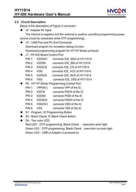
2.2. Circuit Description<br />
Below is the description of Figure 2 connector:<br />
J4 : Adapter 9V Input<br />
The internal is negative and the external is positive, providing programming power<br />
source (must be connected while OTP programming).<br />
U7 : USB Port and PC End Connector<br />
Download program for emulation debug function<br />
Download programming program for HY11P Series products<br />
J1 : HY-ICE Board Control Port<br />
PIN 1 ICESDO connects ICE_SDO of HY11S14<br />
PIN 2 ICESDI connects ICE_SDI of HY11S14<br />
PIN 3 ICESCS connects ICE_CS of HY11S14<br />
PIN 4 VDD connects ICE_VCC of HY11S14<br />
PIN 5 ICESCK connects ICE_SCK of HY11S14<br />
PIN 6 VSS connects ICE_VSS of HY11S14<br />
P6 : HY11P Series Programming Control Port<br />
PIN 1 VPP(6V) connects VPP of the IC<br />
PIN 2 ICECK connects PSCK of the IC<br />
PIN 3 ICESDI connects PSDI . of the IC<br />
PIN 4 ICESDO connects PSDO of the IC<br />
PIN 5 VDD(3V) connects VDD of the IC<br />
PIN 6 VSS connects VSS of the IC<br />
S1 : Program, IC Programming Button<br />
S2 : Blank Check, IC Blank Check Button<br />
D4 : Two color LED;<br />
Red LED:OTP programming, Blank Check…. execution error light<br />
Green LED:OTP programming, Blank Check…execution success light<br />
Green LED:USB or Adapter is powered on<br />
© 2009-2012 HYCON Technology Corp<br />
www.hycontek.com<br />
APD-HYIDE005-V<strong>04</strong>_EN<br />
page7