Air Cooled Packaged Module - Multistack
Air Cooled Packaged Module - Multistack
Air Cooled Packaged Module - Multistack

Create successful ePaper yourself
Turn your PDF publications into a flip-book with our unique Google optimized e-Paper software.
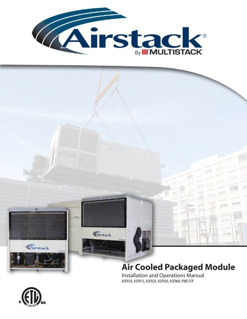
<strong>Air</strong> <strong>Cooled</strong> <strong>Packaged</strong> <strong>Module</strong><br />
Installation and Operations Manual<br />
ASP010, ASP015, ASP020, ASP030, ASP060, PMP, FCP
AIR COOLED PACKAGED MODULE<br />
Table of Contents<br />
Product Introduction<br />
Product Introduction....................................................................................... 4<br />
Model Number Nomenclature.......................................................................... 5<br />
<strong>Module</strong> Description......................................................................................... 7<br />
Installation<br />
Handling of <strong>Module</strong>s..................................................................................... 11<br />
Site Preparation............................................................................................ 11<br />
Installing Single and Multiple <strong>Module</strong>s........................................................... 13<br />
Configuration Information............................................................................. 15<br />
Installation of Free Cool and Pump <strong>Module</strong>..................................................... 16<br />
Main Power................................................................................................... 16<br />
Field Wiring.................................................................................................. 16<br />
ASP Start-Up Data Log................................................................................... 19<br />
Chilled Water Mode Readings......................................................................... 20<br />
Installation Checklist..................................................................................... 21<br />
Operation<br />
1.Chiller Identification................................................................................... 22<br />
2.Theory of Operation.................................................................................... 22<br />
3.Fail to Run.................................................................................................. 22<br />
4.Pressure Reading........................................................................................ 23<br />
5.Strainer Cleaning........................................................................................ 23<br />
6.Refrigerant Charge / Evacuation.................................................................. 23<br />
7.Superheat / Sub Cooling.............................................................................. 23<br />
8.Pressure Relief Valve.................................................................................. 24<br />
9.Filter Driers................................................................................................ 24<br />
10.Compressor Oil Level................................................................................. 24<br />
11.Daily Log Sheet......................................................................................... 24<br />
12.Annual Maintenance................................................................................. 24<br />
13.Annual Maintenance Checks...................................................................... 24<br />
14. Compressor Failure................................................................................... 25<br />
15.Heat Exchangers....................................................................................... 25<br />
16. Low Ambient Option................................................................................ 26<br />
17.Trouble Shooting ASP................................................................................ 26<br />
3
AIR COOLED PACKAGED MODULE<br />
Introduction<br />
The <strong>Multistack</strong>® “ASP” is a modular air-cooled chiller system with a nominal capacity of 10, 15, 20, 30 and 60 tons per module. The chiller system could<br />
consist of a master module (front module with controller), front and rear modules, free cooling module, and a pump module. This system utilizes a fully<br />
hermetic scroll compressor, 316 stainless-steel-brazed plate heat exchanger, four or six row copper tube or microchannel, aluminum fin condenser coils<br />
and a microprocessor– based control. Operating capacity is based on the entering chilled liquid temperature. Precise control and system reliability is best<br />
served in this fashion.<br />
This manual was created for the express purpose of assisting the owner or installing contractor of the <strong>Multistack</strong> ASP <strong>Packaged</strong> <strong>Air</strong> <strong>Cooled</strong> Product. Please<br />
review the material contained in this document carefully before installing and operating this equipment. Additional inquires regarding installation and<br />
operation should be directed to <strong>Multistack</strong> or its authorized agents. Failure to handle, install and operate this equipment in accordance with this manual<br />
may result in damage to the equipment and/or personal injury. Failure to comply may void some or all of the <strong>Multistack</strong> warranty options.<br />
Any questions regarding the content of this Installation Manual, the handling or installation of the <strong>Multistack</strong> Chiller components, should be directed<br />
immediately to your authorized representative or to the Service Department at (608) 366-2400 or FAX (608) 366-2450.<br />
4
AIR COOLED PACKAGED MODULE<br />
Introduction<br />
Model Number Nomenclature<br />
The new model numbers will be effective for any new module ordered after July 1, 2011. Any existing orders will not change.<br />
<strong>Air</strong> <strong>Cooled</strong> <strong>Packaged</strong> <strong>Module</strong><br />
Existing<br />
ASP 30 X 1 H 1 A 0 R410A<br />
New<br />
ASP 030 X C/N 1 1 H 1 A L 1 A A 1 S -410A<br />
Refrigerant<br />
Fan Configuration 6<br />
Series<br />
Power Connection (1 - Direct Connect, 2 - Multiple <strong>Module</strong> Connections)<br />
Voltage 2<br />
Frame Designation 1 - 32 x 58, 2 - 36 x 72, 3 - 36 x 84, 4 - 72 x 84, 5 - other3 - 36 x 84, 4 - 72 x 84, 5 - other)<br />
No. of Refrigerant Circuits ( 1 - single , 2 - dual, 4 - four)<br />
AHRI Certified (C - certified, N - Not certified)<br />
Compressor Type 1<br />
<strong>Module</strong> Nominal Capacity (10-75 tons, needs 3 digits)<br />
Condenser Coating 5<br />
Condenser 4<br />
Evaporator 3<br />
Ambient ( L - Low, S - Standard, H - high, C - low & high)<br />
Voltage (H - 460/3/60, C for 575/3/60, E for 400/3/50)<br />
Application (A - <strong>Air</strong> <strong>Cooled</strong>, D - Cond Unit, H - Heat Recovery, R - Heat Pump)<br />
1<br />
B - Bristol, C - Trane Cornerstone, R - Bitzer Screw, S - Trane Scroll, T - Danfoss Turbocor, Z - Copeland scroll (old elec), X - Copeland Scroll (ZP), A - Copeland Scroll (ZR)<br />
2<br />
A - 208/3/60, L - 230/3/60, H - 460/3/60, C - 575/3/60, D - 200/3/50, E - 400/3/50, F - 380/3/60, S - 220/230/1/60, V - Other<br />
3<br />
A - Brazed SS, B - Brazed SMO, C- S&T copper, D - S&T cu-Ni, Z - Other<br />
4<br />
A - Cu tube Al fin, B - Cu tube Cu fin, C- Microchannel, V - Other<br />
5<br />
A - None, B - Bronzeglow, H - Heresite, E - Electrofin, V - Other<br />
6<br />
S - Standard, H - High static, L -Low sound, V -Other<br />
Pump <strong>Module</strong><br />
PMP 2 015 A H S M Y<br />
Misc Other Comp (Y - Yes other comp., N - No other comp.)<br />
Glycol Shot Feeder (M - Mini shot feeder & Exp tank, T - Exp tank, N - None)<br />
Water Piping (C - Copper, S - Stainless, P - PVC, B - Black iron, V - Other)<br />
Voltage 1<br />
Configuration (A - 100% Redundant, D - Dualarm configuration, S - Single pump)<br />
Pump Horsepower (HP of one pump)( Three digits)<br />
Frame Designation ( 1 - 32 x 58, 2 - 36 x 72, 3 - 36 x 84, 4 - 72 x 84, 5- other, 9 - Indoor)<br />
Series (PMP, Pump <strong>Module</strong>)<br />
1<br />
A - 208/3/60, L - 230/3/60, H - 460/3/60, C - 575/3/60, D - 200/3/50, E - 400/3/50, F - 380/3/60, S - 220/230/1/60, V - Other<br />
5
AIR COOLED PACKAGED MODULE<br />
Introduction<br />
Free Cool <strong>Module</strong><br />
FCP 2 H C A A S<br />
Fan Config (S - Standard, V - Other)<br />
Coil Coating (A - None, B - Bronzeglow, H - Heresite, E - Electrofin, V - Other)<br />
Coil ( A - Cu tube Al fin, B - Cu tube Cu fin, C- Microchannel, V - Other)<br />
Water Piping (C - Copper, S - Stainless, P - PVC, B - Black iron, V - Other)<br />
Voltage 1<br />
Frame Designation ( 1 - 32 x 58, 2 - 36 x 72, 3 - 36 x 84, 4 - 72 x 84, 5- other)<br />
Series (FCP - FreeCool <strong>Module</strong>, DCP - Dry Cooler, RCP - Remote Condensing Unit)<br />
1<br />
A - 208/3/60, L - 230/3/60, H - 460/3/60, C - 575/3/60, D - 200/3/50, E - 400/3/50, F - 380/3/60, S - 220/230/1/60, V - Other<br />
Accessory <strong>Module</strong><br />
ACP 2 H C 180 M B S C<br />
Voltage 1<br />
Series (ACP - Accessory Component <strong>Module</strong>)<br />
<strong>Air</strong> Separator ( Y - Yes, N - None)<br />
Glycol Shot Feeder (M - Mini shot feeder & Exp tank, T - Exp tank, N - None)<br />
Tank Volume (Three digits)(Gallons)<br />
Water Piping (C - Copper, S - Stainless, P - PVC, B - Black iron, V - Other)<br />
Frame Designation ( 1 - 32 x 58, 2 - 36 x 72, 3 - 36 x 84, 4 - 72 x 84, 5- other)<br />
Strainer materials of construction (B - Bronze, C - Copper, S - Stainless, V - Other)<br />
Basket Strainer (S - Single, D - Duplex, L - Lakos, N- None)<br />
1<br />
A - 208/3/60, L - 230/3/60, H - 460/3/60, C - 575/3/60, D - 200/3/50, E - 400/3/50, F - 380/3/60, S - 220/230/1/60, V - Other<br />
6
AIR COOLED PACKAGED MODULE<br />
Introduction<br />
<strong>Multistack</strong> ASP<br />
The chiller will consist of modules (one master, front or back), with an optional<br />
free cooling module (no compressors), an optional water pump module, optional<br />
water holding tank module (not pictured) and optional glycol feeder module<br />
(not pictured).<br />
Master <strong>Module</strong><br />
The master module for each chiller is designated at the factory and is<br />
equipped with the master microprocessor display.<br />
Front <strong>Module</strong><br />
Front <strong>Module</strong>s contain the (4”, 6” or 8”) water header distribution pipes and<br />
has a slave control board. This module will bolt together with the rear module.<br />
Note: ASP-020X, -030X and -060X uses 6” header.<br />
Rear <strong>Module</strong><br />
This module will be attached to the front module by vertical frame bolts and<br />
the evaporator is connected by cross over pipes to the front modules water<br />
header pipes. It also has its own slave board. (There is no rear module on<br />
the ASP-060X)<br />
Pump Package <strong>Module</strong><br />
This module contains a centrifugal dual-arm pump and water distribution<br />
headers. This module is for installations where no pump is provided for the<br />
chilled water system or when additional pumping capacity is required.<br />
Note: Several configurations of pump modules are available. Typical<br />
pump is shown.<br />
7<br />
Free Cooling <strong>Module</strong>s<br />
This module has fin and tube coils for free cooling operation and no mechanical<br />
refrigeration (no compressors). The module contains a three-way diverting<br />
valve for either enabling free cooling or bypass for mechanical cooling.<br />
Note: Free cool modules can come as fronts (with headers) or rears<br />
(without headers).
AIR COOLED PACKAGED MODULE<br />
Introduction<br />
Standard ASP-010, -015, -020, -030 Diagrams<br />
2”<br />
NUMBER OF MODULES X “A” + 4”<br />
ASP-010X, -015X ASP-020X ASP-030X<br />
NOTES:<br />
1. NO OBSTRUCTIONS ALLOWED ABOVE CONDENSER FANS.<br />
2. REQUIRED SERVICE CLEARANCE AT MODULE ENDS: 36”.<br />
3. REQUIRED AIR INTAKE CLEARANCE: 42”. (Unobstructed)*<br />
4. REQUIRED CLEARANCE FROM ANY HIGH VOLTAGE PANEL: 42”<br />
TOP VIEW<br />
“D”<br />
DISCHARGE<br />
“D”<br />
DISCHARGE<br />
CONDENSER COIL<br />
ELECTRICAL PANEL<br />
“C”<br />
INTAKE<br />
INTAKE<br />
“C”<br />
FRONT VIEW<br />
FRONT VIEW<br />
2”<br />
“B”<br />
“A”<br />
2”<br />
“D”<br />
ASP-010X, -015X ASP-020X ASP-030X<br />
NOTES:<br />
1. NO OBSTRUCTIONS ALLOWED ABOVE CONDENSER FANS.<br />
2. REQUIRED SERVICE CLEARANCE AT MODULE ENDS: 36”.<br />
3. REQUIRED AIR INTAKE CLEARANCE: 42”.*<br />
4. REQUIRED CLEARANCE FROM ANY HIGH VOLTAGE PANEL: 42”.<br />
5. REQUIRED CLEARANCE FROM ANY GROUNDED WALL: 36”.<br />
6. NO CLEARANCE REQUIRED FROM REAR.<br />
DISCHARGE<br />
CONDENSER COIL<br />
ELECTRICAL PANEL<br />
“C”<br />
INTAKE<br />
FRONT VIEW<br />
RIGHT SIDE VIEW<br />
*Note: If insullation is in a pit or near walls that are taller than modules, please contact <strong>Multistack</strong> for clearances.<br />
REAR VIEW<br />
8
AIR COOLED PACKAGED MODULE<br />
Introduction<br />
Standard ASP-060 Diagrams*<br />
ASP-060X<br />
NOTES:<br />
1. NO OBSTRUCTIONS ALLOWED ABOVE CONDENSER FANS.<br />
2. REQUIRED SERVICE CLEARANCE AT MODULE ENDS: 42”.<br />
3. REQUIRED AIR INTAKE (FRONT) CLEARANCE: 42”.<br />
4. REQUIRED CLEARANCE FROM ANY HIGH VOLTAGE PANEL: 42”.<br />
ASP-060X (with single fan option)<br />
NOTES:<br />
1. NO OBSTRUCTIONS ALLOWED ABOVE CONDENSER FANS.<br />
2. REQUIRED SERVICE CLEARANCE AT MODULE ENDS: 42”.<br />
3. REQUIRED AIR INTAKE (FRONT) CLEARANCE: 42”.<br />
4. REQUIRED CLEARANCE FROM ANY HIGH VOLTAGE PANEL: 42”.<br />
*All ASP-060X units come standard with four multi-blade vane axial condenser fans. There is also a single fan unit available with a Low Sound (poly-resin reinforced) Blade or<br />
Ultra Low Sound (fiberglass construction) Blade option. Testing has shown a sound reduction of 6dB with the Low Sound and an additional 4dB with the Ultra Low Sound design.<br />
9
AIR COOLED PACKAGED MODULE<br />
Introduction<br />
ASP-060X (with single fan option)<br />
NOTES:<br />
1. NO OBSTRUCTIONS ALLOWED ABOVE CONDENSER FANS.<br />
2. REQUIRED SERVICE CLEARANCE AT MODULE ENDS: 42”.<br />
3. REQUIRED AIR INTAKE (FRONT) CLEARANCE: 42”.<br />
4. REQUIRED CLEARANCE FROM ANY HIGH VOLTAGE PANEL: 42”.<br />
5. REQUIRED CLEARANCE FROM ANY GROUNDED WALL: 42”, NON-GROUNDED WALL: 36”.<br />
ASP-060X<br />
NOTES:<br />
1. NO OBSTRUCTIONS ALLOWED ABOVE CONDENSER FANS.<br />
2. REQUIRED SERVICE CLEARANCE AT MODULE ENDS: 42”.<br />
3. REQUIRED AIR INTAKE (FRONT) CLEARANCE: 42”.<br />
4. REQUIRED CLEARANCE FROM ANY HIGH VOLTAGE PANEL: 42”.<br />
5. REQUIRED CLEARANCE FROM ANY GROUNDED WALL: 42”, NON-GROUNDED WALL: 36”.<br />
10
AIR COOLED PACKAGED MODULE<br />
Installation<br />
Handling of <strong>Module</strong>s<br />
If the <strong>Multistack</strong> product is damaged in any way during shipping and handling by the transportation company or any of it’s agents, the owner, or installing<br />
contractor should promptly file a claim with the transportation company and advise <strong>Multistack</strong>. It is very important to note any damage on the bill of<br />
lading when signing for the delivery of the chiller. Digital photos are also helpful.<br />
Fork Lift or Pallet Jack<br />
The modules can safely be lifted and maneuvered<br />
with a forklift or pallet jack. Forks can be<br />
positioned under the evaporator and between the<br />
tandem compressors.<br />
Use of a Crane or Other Lifting Devices<br />
If lifting modules by crane ensure the slings (do not use chains) do not<br />
damage the modules. The lift points are at the corners of the base of the<br />
chiller. The modules are shipped with the panels pre-fitted. The use of a<br />
spreader bar will prevent damage.<br />
Site Preparation<br />
Below components are required to ensure proper performance of the AIRSTACK® ASP chiller. All piping must be properly supported at coupling<br />
connections and suitable intervals. It is the responsibility of the installing contractor to ensure all water connections conform to local and national<br />
codes. The drawing shows piping exiting on right end. Depending on location of master module, exit can be on either end.<br />
*<br />
Supplied by <strong>Multistack</strong>.<br />
Supplied and installed by others.<br />
*Install system ECHW sensor external to Master module if doing variable flow.<br />
11
AIR COOLED PACKAGED MODULE<br />
Installation<br />
Pipe System Flushing Procedure<br />
Prior to connecting the <strong>Multistack</strong> chiller to the water/glycol-piping loop, the system piping should be flushed with a detergent and hot water (110-130º F) to remove<br />
previously accumulated dirt and/or other organic residue. After removal of organic residue, flushing should continue with a diluted phosphoric, sulfamic, or citric acid<br />
mixture if inorganic scale is present in system. (Note: Cleaning chemicals such as Nu-Calgon “Imperial Grade” Scale Remover part number 4360-84 or equivalent suitable<br />
for both organic residue and scale removal may be substituted). Any other detergents and acids shall not be combined unless approved by chemical manufacturers.<br />
Only chemicals compatible with 316 stainless steel, copper and carbon steel shall be used. (Any concentrations of hydrochloric or sulfuric acid or chloride containing<br />
chemicals shall not be allowed to come in contact with copper brazed 316 stainless steel evaporators.)<br />
During the flushing, 30 mesh (max.) Y strainers (or acceptable equivalent) shall be in place in the system piping and examined periodically as necessary to remove<br />
collected residue. The flushing process shall take no less than 6 hours, or until the strainers when examined after each flushing are clean. Old systems with heavy<br />
encrustation shall be flushed for a minimum of 24 hours and may take as long as 48 hours before the filters run clean. Detergent and acid concentrations shall be used<br />
in strict accordance with the respective chemical manufacturers instructions. After flushing, the system loop shall be purged with clean water for at least one hour to<br />
ensure that all residual cleaning chemicals have been removed. Prior to supplying water to the <strong>Multistack</strong> chiller, the Water Treatment Specification shall be consulted<br />
for requirements regarding the water quality during chiller operation. The <strong>Multistack</strong> service literature shall be available to the operator and/or service contractor and<br />
consulted for guidelines concerning preventative maintenance.<br />
Clearances<br />
Required Service Clearance at <strong>Module</strong>...................... 36”<br />
Required <strong>Air</strong> Intake Clearance................................... 42”<br />
Required Clearance From Any High Voltage Panel..... 42”<br />
Water Treatment/Specifications<br />
Supply water for the evaporator water circuits shall be analyzed and treated by a professional water treatment specialist who is familiar with the operating conditions<br />
and materials of construction specified for the heat exchangers, headers and associated piping. Cycles of concentration shall be controlled such that recirculated water<br />
quality for modular chillers, using 316 stainless steel brazed plate heat exchangers and carbon steel headers, is maintained within the following parameters:<br />
Modular Chiller Water Quality<br />
ph >7 and
AIR COOLED PACKAGED MODULE<br />
Installation<br />
Installing Single and Multiple <strong>Module</strong>s<br />
The modules should be mounted on a level surface with steel rails. This will ensure proper alignment of<br />
all fittings.<br />
Rails should run parallel with module water flow (headers). For maximum stability three rails should be<br />
used, one rail for each outside edge and one rail to be shared in the center.<br />
The outside rails should be placed flush with outside frame. Internal rail shares half the distance (2”) with<br />
Rear and Front modules.<br />
To ensure all warranties and a successful installation, a Factory Authorized Technician is required<br />
to perform start-up of the <strong>Multistack</strong> Chiller. If start-up is to be performed directly by <strong>Multistack</strong>,<br />
a minimum of two weeks notice is required. Please call the <strong>Multistack</strong> Service Department at<br />
(608) 366-2400 to schedule.<br />
1. Starting with the master front modules,<br />
position on rails (27” center to center for<br />
010X and 015X; 32.5” for 020X, 030X and<br />
060X ).<br />
2. Lubricate rails with solid vegetable shortening<br />
(Crisco) or other non-petroleum lubricant.<br />
3. For rear modules, install the evaporator heat<br />
exchanger connecting pipes. Also install the<br />
provided CHW sensor into the leaving pipe.<br />
The 60 ton module consists of a front and rear<br />
portion for one module.<br />
Note: Consult a qualified seismic expert for seismic restraint information.<br />
4. Lubricate gaskets with a vegetable-based lubricant<br />
and hand tighten only. Make sure the bottom<br />
connector pipe and the sensor pocket is positioned to<br />
accept the sensor for the rear module.<br />
5. Note: If the chiller has a single point power<br />
box, the coiled wire and conduit should be run<br />
to the power box as the modules are installed.<br />
The conduit is marked.<br />
13
AIR COOLED PACKAGED MODULE<br />
Installation<br />
6. Termination of each module to the power box<br />
should be done by the electrician.<br />
7. Position the rear module on the rails. Align the<br />
rear module with the front module.<br />
8. Fit the connector pipes from the front module to the rear<br />
module, lubricate the gasket, and tighten both front<br />
and rear couplings at this time. You may need to slide<br />
the evaporator mounting plate forward or backward to<br />
accomplish this.<br />
9. By loosening the four bolts on the plate you can slide<br />
the evaporator to the correct distance. If further<br />
adjustments are needed, you can loosen the header<br />
pipes and front evaporator plate as well.<br />
The Next Step<br />
For installation of subsequent modules, follow the same procedure<br />
as discussed previously, always begin with the front module.<br />
Before installing further rear modules, align the water header<br />
pipes, lubricate and install the gaskets and couplings connecting<br />
to the previous modules header pipe. When bolting the second full<br />
module to the first full module, align the three outer holes on each<br />
end and install the 3/8” bolts provided.<br />
10. To secure the front and rear modules, align the three holes on<br />
both ends and install the (six) 3/8” bolts provided.<br />
14
AIR COOLED PACKAGED MODULE<br />
Installation<br />
IMPORTANT MODULE CONFIGURATION INFORMATION<br />
PMP: ASP Pump <strong>Module</strong><br />
1. When present, a Pump <strong>Module</strong> is only allowed in the Front position.<br />
2. Incoming water to the chiller system must enter at the Pump <strong>Module</strong>.<br />
3. Leaving water from the chiller system may be from either end of the chiller.<br />
FCP: Free Cool <strong>Module</strong><br />
1. When present, incoming system water must enter through the Free Cool<br />
<strong>Module</strong>s prior to entering an ASP-010X, 015X, 020X, 030X or 060X Chiller<br />
<strong>Module</strong>.<br />
2. You may not attach a Rear Free Cool <strong>Module</strong> to a Front ASP-010X, 015X,<br />
020X, 030X or 060X Chiller <strong>Module</strong>.<br />
ACP: ASP Glycol Feeder <strong>Module</strong><br />
1. An ACP Glycol Feeder <strong>Module</strong> may be attached in any rear position.<br />
ASP-010X, 015X, 020X, 030X or 060X<br />
Chiller <strong>Module</strong><br />
1. The maximum number of ASP-010X, 015X, 020X, 030X or 060X modules<br />
with a single Master <strong>Module</strong> is 14 (i.e., (1) Front-Master, (6) Front- Slaves, and<br />
(7) Rear-Slaves).<br />
2. You may have more than one Master <strong>Module</strong> in a single chiller bank.<br />
3. Piping sides of an ASP-010X, 015X, 020X, 030X or 060X chiller without Free<br />
Cool or Pump <strong>Module</strong>s attached are field selectable.<br />
LEGEND<br />
First Letter<br />
M=Master Chiller <strong>Module</strong> (ASP-010X, 015X, 020X, 030X or 060X)<br />
S = Slave Chiller <strong>Module</strong> (ASP-010X, 015X, 020X, 030X or 060X)<br />
P= Pump <strong>Module</strong> (PMP)<br />
F = Free Cool <strong>Module</strong> (FCP)<br />
G = Glycol Feeder <strong>Module</strong> (ACP)<br />
Second Letter<br />
F = Front <strong>Module</strong><br />
R = Rear <strong>Module</strong><br />
ASP-010X, 015X, 020X or 030X<br />
CONFIGURATIONS SAMPLES<br />
Tank PF FF MF<br />
SR<br />
PF<br />
PF<br />
FR<br />
PF<br />
SR<br />
MF<br />
SR<br />
PF<br />
FR<br />
PF<br />
SR<br />
MF<br />
SR<br />
MF<br />
FR<br />
FF<br />
GR<br />
SF<br />
SR<br />
MF<br />
SR<br />
FF<br />
SR<br />
SF<br />
SR<br />
SF<br />
SR<br />
MF<br />
SR<br />
ASP-060X CONFIGURATION SAMPLES*<br />
SF<br />
SF<br />
SR<br />
SF<br />
SR<br />
SF<br />
SR<br />
MF<br />
SR<br />
SF<br />
SR<br />
SF<br />
SR<br />
MF<br />
SR<br />
SF<br />
SF<br />
SR<br />
SF<br />
SF<br />
SF<br />
MC<br />
FF FF SF SF<br />
MC<br />
Front of Chiller Bank is Facing the<br />
Bottom of he Page<br />
(Master <strong>Module</strong> location determines front of chiller)<br />
For other configurations, contact your local <strong>Multistack</strong>® Representative.<br />
Tank<br />
PUMP<br />
SF<br />
SF<br />
MC<br />
MC<br />
PUMP FF FF SF SF<br />
*Rear modules are an invalid configuration for the ASP060X<br />
15
AIR COOLED PACKAGED MODULE<br />
Installation<br />
Free Cool and Pump <strong>Module</strong>s<br />
Top Header: This header is for CHW water leaving the free cool coils. If return<br />
CHW enter on the free cool module this should be capped on the CHW inlet side.<br />
This header sends water from the free cool module to the mechanical modules<br />
for additional cooling.<br />
Middle Header: This connection is for the inlet water to the free cool module.<br />
If the connection is to a mechanical module, the header end closest to the<br />
mechanical module should be capped.<br />
Bottom Header: This header is for CHW going to the building. If the LCHW<br />
exits through a mechanical module on the opposite end, this header would not<br />
be used.<br />
Main Power<br />
Locate the power distribution box on the specified end of the chiller. Wire and<br />
conduit will need to be run from the distribution box to each module of the<br />
chiller. The wire and conduit may be pre-sized and fabricated at the factory. It<br />
is the responsibility of the installer to connect main power to modules before<br />
start-up.<br />
Field Wiring<br />
It is the responsibility of the contractor to supply and install a flow switch in the<br />
LCHW piping. The master module of the ASP chiller has inputs for the following<br />
options: remote start/ stop, run status, system alarm, 0-10V or 4-20ma input, and<br />
remote communication. Supply and return CHW sensors,module communication<br />
plugs, and communication interface cables are all provided with the chiller. The<br />
sensors and cables will be installed and tested by the Factory Authorized Start-Up<br />
Technician. (See electrical diagrams for locations of all inputs/ outputs.)<br />
16
AIR COOLED PACKAGED MODULE<br />
Installation<br />
Master Controller Communication<br />
This is the computer controller that is installed on the master module and controls all connected modules.<br />
<strong>Module</strong> Slave Board Communication<br />
Each front and rear module has one of these. This board transfers communication from one module to the next.<br />
<strong>Module</strong> Communication<br />
All modules are linked together through a communication cable. The communication port is J11 on the module slave board.<br />
17
AIR COOLED PACKAGED MODULE<br />
Installation<br />
Chilled Water Temperature Sensors<br />
These sensors are factory supplied and field installed on the leaving chilled water header stubs. The master module also has a return water sensor<br />
(top header stub). On Variable Flow applications, a return CHW sensor well must be supplied external and field installed as well.<br />
Compressor Pressure Transducers<br />
These are factory installed on the suction and discharge lines of each refrigeration circuit to monitor the suction and discharge pressures (circled).<br />
Sensor Well<br />
The factory supplied, and field installed, LCHW system sensor well should be installed near the master module. Sensor well is 1/2” pipe thread. The master<br />
modules LCHW System sensor will should be installed in this well. On Variable Flow applications, a system ECHW sensor well is also provided.<br />
18
AIR COOLED PACKAGED MODULE<br />
Installation<br />
START-UP DATE: _____________________________________ SHIP DATE:_____________________________________<br />
JOB NAME:_______________________________________ JOB NUMBER:_____________________________________<br />
ADDRESS:_____________________________________________________________________________________<br />
MULTISTACK REPRESENTATIVE:_ ________________________________________________________________________<br />
MODEL NUMBER:_ ________________________________________________________________________________<br />
MODULE SERIAL NUMBERS (Indicate Master Controller with an X, Indicate “FC” if Free Cool, Indicate “P” if Pump <strong>Module</strong>)<br />
1._ _________________________________________ 7.______________________________________________<br />
2._ _________________________________________ 8.______________________________________________<br />
3._ _________________________________________ 9.______________________________________________<br />
4._ ________________________________________ 10.______________________________________________<br />
5._ ________________________________________ 11.______________________________________________<br />
6._ ________________________________________ 12.______________________________________________<br />
Master Controller Program #_ _________________________________________________________________________<br />
INSTALLATION CHECKLIST CIRCLE CORRECT RESPONSE<br />
1. Chiller mounted on rails and isolators YES NO<br />
2. Any visible damage YES NO<br />
If yes, detail:_____________________________________________________________<br />
3. Any obvious oil and/or refrigerant leaks YES NO<br />
If yes, detail:<br />
4. Sensor pockets installed YES NO<br />
5. Chilled water flow or DP switch installed Type YES NO<br />
6. Chilled water system strainer installed Type YES NO<br />
7. Chilled water isolation valves installed YES NO<br />
ELECTRICAL AND CONTROLS CHECKLIST CIRCLE CORRECT RESPONSE<br />
1. All electrical connections tight and correct YES NO<br />
2. Power wiring sufficient to carry RLA YES NO<br />
3. Voltage levels:<br />
PHASES 1 + 2 ________________2 + 3_ __________ 1 + G_ __________ 2 + G ___________ 3 + G___________<br />
4. Set system variables to site conditions Yes No<br />
Upset__________ Manual Range_ _________ Sequence_ _________<br />
Loset__________ Manual Offset__________ Indexing___________<br />
VSP___________ Fan Setpoint_ __________<br />
TDiff_ _________ Fan Offset_____________<br />
Load Limit_______ HP Cutout_____________<br />
5. Set time and date Yes No<br />
6. Factory Set-Up variables:<br />
Chiller type: q Standard q Low Temp q Low Ambient<br />
Variable Flow: q Enabled q Disabled<br />
Min Flow Bypass: q Enabled q Disabled<br />
19
AIR COOLED PACKAGED MODULE<br />
Installation<br />
<strong>Air</strong> <strong>Cooled</strong> Supplement<br />
Start Time:<br />
Stop Time:<br />
ECHW<br />
Temperatures<br />
LCHW<br />
<strong>Module</strong> Circuit<br />
1.<br />
A.<br />
B.<br />
2.<br />
A.<br />
B.<br />
3.<br />
A.<br />
B.<br />
4.<br />
A.<br />
B.<br />
5.<br />
A.<br />
B.<br />
6.<br />
A.<br />
B.<br />
CURRENT TEMPERATURE HIGH<br />
PHASE A PHASE B PHASE C SUCTION LOCHW PRESSURE<br />
LOW<br />
PRESSURE<br />
Observations<br />
20
AIR COOLED PACKAGED MODULE<br />
Installation<br />
CUSTOMER:_______________________________________________________________________________________<br />
JOB NAME:_ _______________________________________________________________________________________<br />
JOB LOCATION:_____________________________________________________________________________________<br />
CUSTOMER ORDER NUMBER:_________________________________________________________________________<br />
The work checked below is in process and will be completed by: (Date)_ _____________________________________________ . The service<br />
of a <strong>Multistack</strong> Authorized Start-up Engineer is requested on this date and it is understood that if the work checked below is not completed, the engineer’s time and<br />
expenses will be billed to us by <strong>Multistack</strong>. Terms Net 30 days. <strong>Multistack</strong> to be notified at least ten (10) working days in advance of the start-up date.<br />
Chilled Water Yes No N/A<br />
Piping complete and connected to <strong>Multistack</strong> units. q q q<br />
Water system filled and vented. q q q<br />
Pumps installed (Rotation checked). q q q<br />
Recommended strainers installed. q q q<br />
Controls (3-way valves & by-pass valves, etc.) operable. q q q<br />
Water system operated and flow balanced to meet unit design recommended. q q q<br />
Strainers checked for unusual debris. q q q<br />
Flow or differential pressure switch installed. q q q<br />
Remote <strong>Air</strong> <strong>Cooled</strong> Condenser Yes No N/A<br />
Piping complete and connected to <strong>Multistack</strong> module. q q q<br />
All piping in accordance with good engineering practice. q q q<br />
Hot gas and liquid lines installed correctly. q q q<br />
Low ambient (refrigerant head pressure controls) installed. q q q<br />
Condenser fans controlled on head pressure. q q q<br />
Condenser wired and operational. (correct rotation) q q q<br />
Control wires ran from <strong>Multistack</strong> module to remote condenser. q q q<br />
Electrical Yes No N/A<br />
Power wiring complete and in accordance with nameplate rating on<br />
<strong>Multistack</strong> unit and prepared for connection in accordance with installation manual. q q q<br />
Note: No power is to be applied to unit prior to inspection by <strong>Multistack</strong> engineer.<br />
All interlock wiring complete between control panel and complies with<br />
<strong>Multistack</strong> specifications and with applicable codes. q q q<br />
Miscellaneous Yes No N/A<br />
Thermometer wells, thermometer gauges, control, etc. are installed. q q q<br />
A minimum system load of 50% of total building load is available for testing<br />
and adjusting controls. q q q<br />
We understood that authorized representatives of the installing electrical and piping contractor must be available during the start-up period and that coordination is our<br />
responsibility.<br />
We further understand that the services of <strong>Multistack</strong> Authorized Start-Up Engineer will be furnished for a period of not more than sixteen (16) consecutive normal<br />
working hours and we agree that a charge for time and expenses will be made by <strong>Multistack</strong> if services are required for longer than sixteen (16) consecutive normal<br />
working hours or if repeat calls are required through no fault of <strong>Multistack</strong>.<br />
Signed<br />
Title<br />
Company Telephone<br />
Company Name<br />
Job Location Telephone<br />
Company Location<br />
21
AIR COOLED PACKAGED MODULE<br />
Operations<br />
1. CHILLER IDENTIFICATION<br />
More model numbers for related modules are available on page 5 of this manual. The new model numbers will be effective for any new module ordered after July<br />
1, 2011. Any existing orders will not change.<br />
Existing<br />
ASP 30 X 1 H 1 A 0 R410A<br />
New<br />
ASP 030 X C/N 1 1 H 1 A L 1 A A 1 S -410A<br />
Refrigerant<br />
Fan Configuration 6<br />
Series<br />
Power Connection (1 - Direct Connect, 2 - Multiple <strong>Module</strong> Connections)<br />
Voltage 2<br />
Frame Designation 1 - 32 x 58, 2 - 36 x 72, 3 - 36 x 84, 4 - 72 x 84, 5 - other3 - 36 x 84, 4 - 72 x 84, 5 - other)<br />
No. of Refrigerant Circuits ( 1 - single , 2 - dual, 4 - four)<br />
AHRI Certified (C - certified, N - Not certified)<br />
Compressor Type 1<br />
<strong>Module</strong> Nominal Capacity (10-75 tons, needs 3 digits)<br />
Condenser Coating 5<br />
Condenser 4<br />
Evaporator 3<br />
Ambient ( L - Low, S - Standard, H - high, C - low & high)<br />
Voltage (H - 460/3/60, C for 575/3/60, E for 400/3/50)<br />
Application (A - <strong>Air</strong> <strong>Cooled</strong>, D - Cond Unit, H - Heat Recovery, R - Heat Pump)<br />
1<br />
B - Bristol, C - Trane Cornerstone, R - Bitzer Screw, S - Trane Scroll, T - Danfoss Turbocor, Z - Copeland scroll (old elec), X - Copeland Scroll (ZP), A - Copeland Scroll (ZR)<br />
2<br />
A - 208/3/60, L - 230/3/60, H - 460/3/60, C - 575/3/60, D - 200/3/50, E - 400/3/50, F - 380/3/60, S - 220/230/1/60, V - Other<br />
3<br />
A - Brazed SS, B - Brazed SMO, C- S&T copper, D - S&T cu-Ni, Z - Other<br />
4<br />
A - Cu tube Al fin, B - Cu tube Cu fin, C- Microchannel, V - Other<br />
5<br />
A - None, B - Bronzeglow, H - Heresite, E - Electrofin, V - Other<br />
6<br />
S - Standard, H - High static, L -Low sound, V -Other<br />
2. THEORY OF OPERATION<br />
The <strong>Air</strong>stack ASP chiller provides chilled water to an external load based on the return water temperature as measured by the ASP master control. When the temperature<br />
of the returning water rises above the set point as calculated by the upper set point, the lower set point and the VSP the master controller starts compressors, one at<br />
a time, to produce chilled water. The number of compressors that will start is determined by the program in the master controller based on the temperature being<br />
returned.<br />
When the return chill water approaches the correct set point the master controller starts to turn off compressors as needed. When the return chilled water reaches the<br />
set point or a little below, the master controller will have turned off all the compressors.<br />
During operation of the compressors, the controller will cycle on one or both of the condenser fans in a module according to the refrigerant high pressure.<br />
Some systems have a large heat exchanger which uses a main chiller to chill the return water/glycol. When the chilled water from the main system is cold enough, the<br />
heat exchanger valves open and chill the return water/glycol through the smaller chiller enough that the compressors will not run. If the Heat Exchanger does not chill<br />
the return water/glycol enough, the 3 heat exchanger valves close and the compressors will start and chill the discharge water to the set-point.<br />
3. Fail to Run<br />
<strong>Air</strong>stack ASP systems designed for critical needs have a design that will allow individual modules to run in the event that the master module fails or goes offline or if<br />
certain System Faults occur that would otherwise disable the entire chiller. Each module must be in the Auto mode of operation in order for this OVERRIDE condition to<br />
occur. If the Master Control comes back online and all System Faults are cleared then the control of the compressors will automatically shift back to the master control.
AIR COOLED PACKAGED MODULE<br />
Operations<br />
4. Pressure readings<br />
The operating suction and discharge pressures in the modules are directly related to the temperature of the water flow, condenser temperatures, the ambient<br />
temperature and the cleanliness of the system. If a module is faulting on a High Pressure (HP) fault, you should first check to see that the fans are operating. If both<br />
fans are working check the cleanliness of the condenser coil.<br />
All ASP modules have both, a high pressure and low pressure (LP) cut out setting. Each module will cut out on HP or LP when the programmed limit in the master<br />
control is met. In addition a back up manual HP cut out switch is installed on each module.<br />
A LP fault is an indication of low refrigerant charge in the system. If a module is going out on a LP fault, check the static pressure of the system while the module<br />
is in the off mode. It will be necessary to wait for the system to warm up before checking the pressures by the gauge. If pressures are low, check the circuit for<br />
possible leaks. Call the <strong>Multistack</strong> service department for leak testing procedures.<br />
A further possible cause of a low suction temperature fault could be insufficient water flow. The strainers, filters and pump and valve settings should be checked.<br />
5. Strainer Cleaning<br />
All ASP modules have a 30 mesh filter cartridge in the chilled water inlet header. The purpose of the filter cartridge is to keep debris from entering the heat<br />
exchanger. An external “Y” or basket type strainer should also be installed as a pre-filter to the factory supplied strainers.<br />
There is no set time for cleaning the filter cartridges. The factory recommendation is that the internal filters be removed and cleaned once per year. Sometimes the<br />
filter must be removed more often if the water in the closed loop system has particulates. A good indicator that the strainers need to be cleaned is a “low leaving<br />
water temperature” fault in the module(s) near the discharge side of the chiller.<br />
a. In order to remove the in-line strainers the following steps must be performed.<br />
b. Shut down the chiller and stop the chill water pump<br />
c. Close the inlet and outlet water valves to the chiller<br />
d. Drain the water-glycol from the system and dispose properly. When the water/glycol level is below the top header the system can be safely opened.<br />
e. Remove the 4” Victaulic end cap on the last module on the discharge side. On systems with 2 banks of modules, the upper crossover pipe will also have<br />
to be removed to access the strainer in the second bank of modules. Care should be taken to close the isolation valve for that header.<br />
f. Remove the strainers and clean immediately. A hooked tool may be required to remove the strainers further in the system. This tool can be manufactured<br />
on site.<br />
g. Slowly open the bottom water isolation valve and fill the unit from the bottom up to prevent air from being trapped in the headers. Care should be<br />
taken to check for leaks.<br />
h. Restart the chill water pump and again check for possible leaks, bleed any trapped air from the system and start the chiller.<br />
6. Refrigerant charge / Evacuation<br />
All ASP modules come from the factory charged with the recommended refrigerant volume. Prior to charging, each unit is evacuated to a maximum of 150 microns<br />
and held 15 minutes. The proper refrigerant charge for each module can be found on the module data plate.<br />
On air cooled machines the proper charging procedure is by a calculated weigh-in method. Charging to a full sight glass on air cooled machines will likely result in<br />
over charging as the elbows in the liquid line as well as the liquid line solenoid valve still produce some flashing even with the correct charge. As fans are cycling<br />
the sight glass will also display some bubbling.<br />
7. Superheat / Sub cooling<br />
All ASP modules use a mechanical type expansion valve. By turning the valve adjustment clockwise superheat is increased.<br />
On each module, superheat is set at the factory during the run test. Superheat is set for 10-12°F during the test run. No further adjustments should be necessary<br />
after the module is shipped.<br />
Sub cooling is necessary in the system to prevent flash gas as the refrigerant enters the expansion valve. ASP condensers are sized and charged so that sub cooling<br />
of the liquid refrigerant will take place with no separate sub-cooler being needed. The range of sub cooling is 7-15° F.<br />
23
AIR COOLED PACKAGED MODULE<br />
Operations<br />
8. Pressure Relief Valve<br />
Each module has a 650 psig pressure relief valve installed. The relief valve is installed on the receiver of the module and has a 3/8” flare connection.<br />
9. Filter Driers<br />
ASP modules are built with a factory installed liquid line filter drier. The filter driers are a solid core sweat fitting replaceable type. Some modules have a flare<br />
connection system for the filter drier. In the case of a compressor failure, heat exchanger failure or water contamination in the system, it is always required to<br />
replace the drier.<br />
10. Compressor MOUNTING AND Oil Level<br />
It is very important that the compressors remain tightened on the rubber isolators and base plate in the same manner as shipped. This will prevent any damage<br />
to the refrigerant piping from excess vibration. If replacing a compressor make sure the isolators and mounting brackets get re-installed in the same manner.<br />
The compressors used on ASP modules are oil charged by the compressor manufacturer. Most models have an oil sight glass. Correct oil level should be between<br />
1/8 to 7/8 full on the glass. To ensure no liquid is present in the oil the crankcase heaters should be on a minimum of 24 hours before starting of the compressors.<br />
The factory oil charge volume for each compressor can be found in the Product Data Catalog. The oil used in R-410A compressors use an esther based oil, not a<br />
petroleum based oil. Please do not mix oils when adding oil to a system since they are not compatible and will cause damage<br />
11. Daily log Sheet<br />
On the back page of this manual is a chiller information log sheet. The log sheet can be used daily, weekly or as desired to record operation characteristics of the<br />
chiller. The information recorded on the log sheet can also be very helpful for diagnosing potential problems in the system.<br />
12. Annual Maintenance<br />
Most of the annual maintenance requirements for ASP Chillers involve proper shut-down of the system and if needed cleaning of the heat exchangers. Preventive<br />
Maintenance bulletin #F125 and Heat Exchanger Cleaning Procedures bulletin #F130 describe the recommended procedures for both processes. <strong>Air</strong>stack has<br />
available the 151A Cleaning Kit to assist with this process. Please see the 151A Cleaning Kit bulletin #F126 for more details. All of these bulletins are part of the<br />
standard O&M manual package.<br />
13. ANNUAL MAINTENANCE CHECKS<br />
a. Electrical components<br />
b. Check all external interlocks<br />
c. Inspect compressor terminals<br />
d. Check compressor crankcase heater operation<br />
e. Tighten all electrical terminals, high voltage and low<br />
f. Check and calibrate all compressor safety controls<br />
g. Check and record voltages and amperages for compressors<br />
h. Check and record amperages for pumps and condenser fans<br />
i. Check and calibrate low ambient fan cycling controls<br />
j. Inspect relay contacts for damage or pitting, replace if required<br />
Update Your Maintenance Log Book!<br />
13.1 Refrigeration Circuits<br />
a. Analyze refrigerant with tube type moisture/acid analyzer<br />
b. Check and record refrigerant sub cooling and superheat<br />
c. Check liquid solenoid valves<br />
d. Check expansion valve and sensing bulb connections<br />
24
AIR COOLED PACKAGED MODULE<br />
Operations<br />
13.2 Chilled Water System<br />
a. Clean pump strainers and system strainers<br />
b. Remove header caps and clean the ECHW strainers. Please see the 151A Cleaning Kit bulletin #F126 for more details.<br />
c. Check glycol, inhibitor content in system chilled water<br />
13.3 Cabinet and Related Hardware<br />
a. Dry clean electrical panels, remove debris<br />
b. Apply protective coatings or wax if required<br />
c. Remove rust and apply primer and paint if required<br />
14. Compressor Failure<br />
With any chiller system there is always the chance of a compressor failure. In the event of a failure, proper steps should be taken to determine the cause of the<br />
failure.<br />
a. A motor burn out due to a fault in the motor insulation is quite rare. Most burnouts are actually caused by a mechanical condition or lubrication<br />
problems. In the event of a burnout, proper clean up procedures should be followed.<br />
b. Check all electrical components of the circuit (contactors, fuses, wires, etc.)<br />
c. If necessary perform a system clean up. Nu-Calgon RX-11 Flush or Sporlan System Cleaner work well. Follow the cleaning solutions manufacturers<br />
direction<br />
d. Replace the liquid line filter drier with a burnout core.<br />
e. Evacuate the system to a minimum of 500 microns and hold for 20 minutes<br />
f. Charge the circuit with virgin refrigerant. Charge with liquid into the discharge side of the compressor. See refrigerant charge on nameplate data of<br />
unit for proper amount<br />
g. Run the system 2-3 weeks with the burnout filter core. With the King Valve on the receiver closed, replace with standard core drier. Consideration<br />
should be given that the pipe loop will have refrigerant under pressure and consideration must be given to safety.<br />
15. Heat Exchangers<br />
<strong>Air</strong>stack® uses brazed plate stainless steel heat exchangers for all evaporators. Without proper water treatment or due to abuse, heat exchangers can corrode over<br />
time and eventually develop an internal leak. In such an event it would become necessary to replace the heat exchanger.<br />
Following are steps for field replacement of a failed evaporator heat exchanger:<br />
a. If the refrigerant has not been lost on the failed circuit, you should first do a standard refrigerant recovery<br />
b. Begin by isolating the chiller and draining the water/glycol form the loop<br />
c. Remove the 4” round header pipes that attach to the evaporator (if you have a front module). If rear module remove the crossover pipes from the front<br />
module.<br />
d. Cur the refrigerant lines below the elbows and sweat off remaining pipe<br />
e. Remove old evaporator and replace with new one<br />
f. Fit in copper connections and braze, using a minimum 45% silver solder. Purge with Nitrogen while brazing<br />
g. After brazing first perform a pressure check with Nitrogen. Charge the system to 110 psig and hold for 20 minutes. If the system passes the pressure<br />
test, evacuate to a minimum of 500 microns and hold for 20 minutes. Charge the circuit according to the name plate charge.<br />
If the evaporator heat exchanger has caused water to enter into the refrigerant side, the compressor and condenser should also be checked for possible<br />
contamination. If water has entered into the compressor it is recommended the compressor be replaced as removing all the moisture from the oil is very difficult.<br />
Replacement of the condenser, the expansion valve and installation of a liquid line filter drier with a water core cartridge is also recommended. Evacuate the<br />
circuit to a maximum of 500 microns and let stand for 20 minutes. Charge the circuit and run 2-3 weeks with the high water core cartridge and the replace with<br />
a standard core.<br />
Standard condensers on the ASP module are copper coil with aluminum fin type, however other construction materials may be used. Periodic cleaning of the fins<br />
should be done to keep air-born debris from plugging up the fins and causing high pressure conditions. Confirm the specific material used in construction of the<br />
condenser before cleaning to avoid any possible damage. A coil cleaner suitable for copper and aluminum can be used for the standard condensers.<br />
25
AIR COOLED PACKAGED MODULE<br />
Operations<br />
16. LOW AMBIENT OPTION<br />
For applications requiring operation below 20° F, modules should be ordered with the “Low Ambient” option. “Low Ambient” modules can be operated down to<br />
-20° F. These modules will be equipped with additional refrigerant charge, a larger liquid receiver, and head pressure control valves. The valves used to control<br />
head pressure are the adjustable electronic CDS Stepper Valve along with the fixed setting ORD valve. The CDS Valve holds refrigerant in the condenser to “flood”<br />
the coils by reducing surface area and therefore building the condenser head pressure. The ORD valve will open based on a differential between the compressor<br />
discharge pressure and the receiver liquid pressure. As the differential between pressures increases, the ORD valve will open, allowing hot gas into the liquid line<br />
increasing the liquid pressure. To set the chiller for low ambient operation and to set the CDS valves please see the ASPX Master Controller User Manual.<br />
17. TROUBLE SHOOTING AIR COOLED PACKAGED MODULES<br />
ASP modules use the Carel PCO2 master control. The user manual for the PCO2 controller is located in the O&M package. The user manual details the different<br />
status screen and explanations of system or module faults.<br />
WARNING: Most of the following repairs to the system should only be performed or attempted by a qualified service technician. Failure to adhere to<br />
proper safeguards and safety rules could cause damage to the system and serious injury to personnel.<br />
FAULT<br />
No Display on<br />
Master <strong>Module</strong><br />
EX 1, 2 interlock<br />
EX 4 interlock<br />
Waiting For<br />
Chilled Water<br />
Flow<br />
Low Chill Water<br />
Temp<br />
No Demand<br />
100% Demand<br />
all the time<br />
100% Demand,<br />
chiller won’t<br />
load<br />
SOLUTION<br />
• Check main disconnect for power<br />
• Check circuit breakers in module and J-Box<br />
• Check transformer in modules<br />
• Check for 24v at J1 on board<br />
• Check appropriate interlock component<br />
• Check jumpers on TS2 in master module<br />
• Check for proper rotation, phasing<br />
• Check PPM device<br />
• Check CHW pump<br />
• Check flow switch operation<br />
• Check filter strainers, Basket strainers and Y<br />
strainers<br />
• Check TS2 inputs #3 and #5<br />
• Check LCHW sensor<br />
• Check set points in system variables<br />
• Check for flow restrictions, system and module<br />
• Check entering CHW sensor<br />
• Check set points in system variables<br />
• Check sensor location<br />
• Check entering CHW sensor<br />
• Check set points in the system variables<br />
• Turn chiller on<br />
• Check sensors<br />
• Check load limit setting in system variables menu<br />
FAULT<br />
Excessive<br />
Cycling<br />
High discharge<br />
Pressure (HP)<br />
Low Suction<br />
Pressure (LP)<br />
Low Suction<br />
Temperature<br />
Communication<br />
Error/<br />
pLan Error<br />
Circuit Fault<br />
SOLUTION<br />
• Check VSP setting in system variables<br />
• Check entering CHW sensor location<br />
• Check fan operation<br />
• Check coil condition<br />
• Compare analog pressure reading with digital<br />
• Check fan settings in system variables<br />
• Check refrigerant charge / leaks<br />
• Compare analog pressure reading to digital<br />
• Check expansion valve<br />
• Check solenoid valve<br />
Check suction sensor<br />
Check set points in system variables<br />
Check expansion valve<br />
Check solenoid valve<br />
Check for water flow restrictions<br />
Check settings in system variables<br />
Check cables at J11 communications ports<br />
Check components in control circuit<br />
Check wire crimps in the control circuit<br />
26
sm<br />
1065 Maple Avenue Sparta, WI • Phone (608)366-2400 • Fax (608)366-2450<br />
www.multistack.com<br />
Made in U.S.A.<br />
F122IUM0511