VT591 User Manual - Schick Handel
VT591 User Manual - Schick Handel
VT591 User Manual - Schick Handel

You also want an ePaper? Increase the reach of your titles
YUMPU automatically turns print PDFs into web optimized ePapers that Google loves.
<strong>VT591</strong> <strong>User</strong> <strong>Manual</strong><br />
VT-ENG-591-V1 1005S24<br />
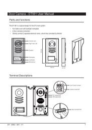
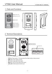
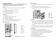
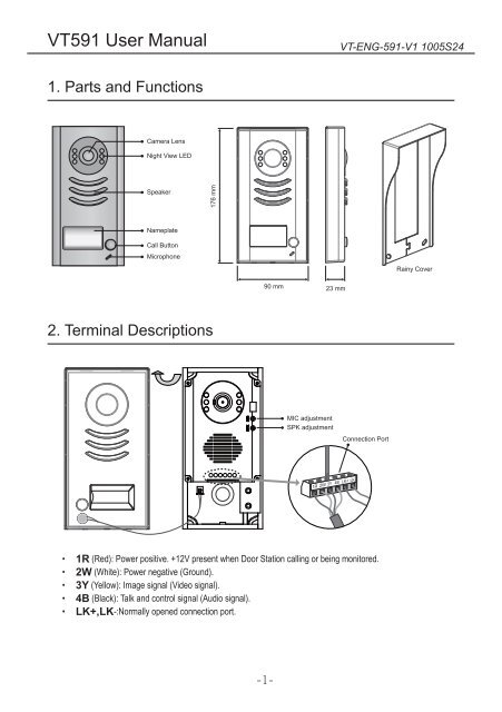
1. Parts and Functions<br />
Camera Lens<br />
Night View LED<br />
Speaker<br />
176 mm<br />
Nameplate<br />
Call Button<br />
Microphone<br />
Rainy Cover<br />
90 mm<br />
23 mm<br />
2. Terminal Descriptions<br />
MIC adjustment<br />
SPK adjustment<br />
Connection Port<br />
1R 2W 3Y 4B LK+ LK-<br />
••<br />
1R (Red): Power positive. +12V present when Door Station calling or being monitored.<br />
••<br />
2W (White): Power negative (Ground).<br />
••<br />
3Y (Yellow): Image signal (Video signal).<br />
••<br />
4B (Black): Talk and control signal (Audio signal).<br />
••<br />
LK+,LK-:Normally opened connection port.<br />
-1-
3. Mounting<br />
3.1 Mounting Without Rainy Cover<br />
1 2 3 4<br />
1<br />
160-165cm<br />
2<br />
3.2 Mounting With Rainy Cover<br />
1 2 3 4<br />
1<br />
2<br />
160-165cm<br />
-2-
3.3 Adjusting Camera Angle<br />
use a screwdriver to loosen the screw and then<br />
adjust the angle of the camera ,then fix the screw.<br />
4. System Wiring and Connections<br />
4.1 Basic Connection<br />
1R 2W 3Y 4B LK+ LK-<br />
Monitor<br />
1R<br />
2W<br />
3Y<br />
4B<br />
Red<br />
White<br />
Yellow<br />
Black<br />
Red<br />
White<br />
Yellow<br />
Black<br />
Shielding Layer of the RVVP Cable<br />
-3-
4.2 Electric Lock Connection<br />
••<br />
Mode1:Door Lock Controlled With Dry Contact<br />
Indoor Monitor<br />
Connection Port<br />
1R 2W 3Y 4B<br />
+<br />
-<br />
1R 2W 3Y 4B LK+ LK-<br />
+<br />
-<br />
Must install external power supply for<br />
lock,and nearly all kinds of electronic lock<br />
can be used.Incidentally,in this mode,you<br />
can continue talking and monitoring during<br />
unlock operation.<br />
Note:<br />
1.The external power supply must be used<br />
according to the lock.<br />
2.The inside relay contact is restricted to<br />
AC or DC 24V/3A.<br />
••<br />
Mode2:Door Lock Controlled With Internal Power<br />
Indoor Monitor<br />
Connection Port<br />
1R 2W 3Y 4B<br />
-<br />
+<br />
1R 2W 3Y 4B LK+ LK-<br />
The lock can be directly connected with<br />
the door station and the power through<br />
monitor.During unlock operation,the<br />
monitor will close screen automatically.<br />
The rated voltage of the lock is 12V,less<br />
than 500mA consumption.<br />
Note:<br />
1.Electronic lock of power-on-to-unlock<br />
shoule be used.<br />
2.The door lock is limited to 12V,and<br />
holding current must be less than 250mA<br />
5. Specifications<br />
Power Supply:<br />
DC 10~12V (Internal Power supply)<br />
Consumption:<br />
200mA in working state (latch not included)<br />
Video Output:<br />
75Ohm, 1Vp-p, CCIR standard (unless specified)<br />
Camera:<br />
76 degree, CCD camera with IR-LED<br />
Working temperature: -10ºC ~ 40ºC<br />
-4-