4. Extending Monitors - Schick Handel
4. Extending Monitors - Schick Handel
4. Extending Monitors - Schick Handel

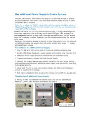
You also want an ePaper? Increase the reach of your titles
YUMPU automatically turns print PDFs into web optimized ePapers that Google loves.
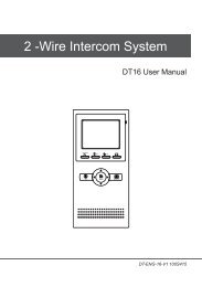
ENGLISH<br />
VIDEO DOOR PHONE SYSTEM<br />
USER MANUAL<br />
VT-ENG-6913-V2 090S413
CONTENT:<br />
1. Parts and Functions ------------------------------1<br />
2. Mounting and Installation------------------------1<br />
3. Standard System Wiring-------------------------2<br />
<strong>4.</strong> <strong>Extending</strong> <strong>Monitors</strong> -------------------------------3<br />
5. <strong>Extending</strong> 2 Outdoor Stations------------------4<br />
6. Operation Instructions----------------------------5<br />
7. Precautions-----------------------------------------9<br />
8. Specifications --------------------------------------9<br />
The model you purchased may not have all the functions<br />
mentioned here, but the operation is simylar.
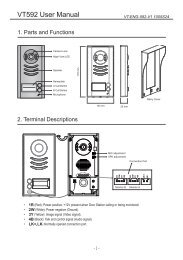
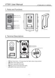
1. Parts and Functions<br />
Microphone<br />
INI-USE<br />
MESG<br />
CALL<br />
UNLOCK<br />
TALK<br />
IN-USE/MESG<br />
LED<br />
CALL button<br />
UNLOCK button<br />
MONITOR/TALK<br />
button<br />
TFT screen<br />
UP button<br />
DOWN button<br />
ENTER button<br />
(+)ADD button<br />
(-)REDUSE button<br />
Power LED<br />
Speaker<br />
Dimensions: 153(H)×250(W)×30(D)<br />
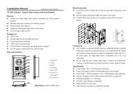
2. Mounting and Installation<br />
145~160 cm<br />
1. Use the screws to fix the Mounting Bracket on the wall.(fitting accesories includes a<br />
Bracket (Two 4X25 screws are needed for fastening the Mounting Bracket), Special 4<br />
core cables to connect with Monitor)<br />
2. Wire the system correctly(see the later connection chapter) then hang the Monitor on<br />
the Mounting Bracket firmly.<br />
-1-
3<br />
2<br />
1<br />
INI-USE<br />
MESG<br />
CALL<br />
UNLOCK<br />
TALK<br />
3. Standard System Wiring<br />
Terminal Discriptions:<br />
●●<br />
●●<br />
●●<br />
●●<br />
1R Power positive. +12V present when Door Station calling or being monitored<br />
2W Power negative (GND)<br />
3Y Image signal (Video signal)<br />
4B Talk and control signal (Audio signal)<br />
It’s recommended to use RVVP 4x0.3mm 2 Shielded Cable. And when distance<br />
is over 30m, we suggest to use additional co-axle cable SYV- 75-3 (RG-59)<br />
connect 3Y and 2W pin.<br />
AC ~<br />
4<br />
* Note 1<br />
1R<br />
2W<br />
3Y<br />
4B<br />
* Note 4<br />
JS-OS2<br />
1R<br />
2W<br />
3Y<br />
4B<br />
DC-<br />
DC+<br />
* Note 2<br />
JS-VP<br />
JS-OS1<br />
1R<br />
2W<br />
3Y<br />
4B<br />
JP-LK<br />
JP-VD<br />
* Note 3<br />
JS/VP<br />
1R<br />
2W<br />
3Y<br />
4B<br />
Back View<br />
Red<br />
White<br />
Yellow<br />
Black<br />
Red<br />
White<br />
Yellow<br />
Black<br />
LB<br />
1R<br />
2W<br />
3Y<br />
4B<br />
1R<br />
2W<br />
3Y<br />
4B<br />
●●<br />
●●<br />
●●<br />
Note 1: Plug the AC Adaptor to the AC power socket properly.<br />
Note 2: JS-LK is used for Lock selection, remove the jumper if use the Monitor power to supply the Lock.<br />
Refer to the Outdoor station manual.<br />
Note 3: JS-VD is used for setting the video impedance. When there is only one Monitor, keep the jumper<br />
(which is already on JSP-VD ). But when multi <strong>Monitors</strong> are installed, be sure of taking away all JS-VD of<br />
<strong>Monitors</strong> except only the last Monitor.<br />
● ● Note 4: LB includes 3 wiring Terminals: ‘1’-Normally Opened Terminal, ‘2’- Common Terminal, ‘3’-<br />
Normally Closed Terminal. If the Lock is activated when powering, connect it between ‘1’ and ‘2’ terminal; if<br />
the Lock is activated when power-off, connect it between ‘2’ and ‘3’ terminal.<br />
-2-
<strong>4.</strong> <strong>Extending</strong> <strong>Monitors</strong><br />
INI-USE<br />
INI-USE<br />
JP-VD Removed!<br />
3<br />
2<br />
1<br />
LB<br />
INI-USE<br />
Red<br />
White<br />
Yellow<br />
Black<br />
1R<br />
2W<br />
3Y<br />
4B<br />
JS-VP<br />
CALL<br />
AC ~<br />
AC ~<br />
CALL<br />
MESG<br />
CALL<br />
TALK<br />
AC ~<br />
MESG<br />
CALL<br />
-<br />
MESG<br />
CALL<br />
UNLOCK<br />
TALK<br />
MESG<br />
-<br />
UNLOCK<br />
MESG<br />
UNLOCK<br />
CALL<br />
TALK<br />
TALK<br />
TALK<br />
TALK<br />
Back View<br />
Back View<br />
Back View<br />
MESG<br />
1R<br />
2W<br />
DC-<br />
3Y<br />
DC+<br />
4B<br />
1R<br />
2W<br />
JP-LK<br />
3Y<br />
4B<br />
JP-VD<br />
1R<br />
2W<br />
3Y<br />
4B<br />
JS-OS2 JS-OS1 JS/VP<br />
DC<br />
DC+<br />
JP-LK<br />
JP-VD<br />
1R<br />
2W<br />
3Y<br />
4B<br />
1R<br />
2W<br />
3Y<br />
4B<br />
1R<br />
2W<br />
3Y<br />
4B<br />
JS-OS2 JS-OS1 JS/VP<br />
DC<br />
DC+<br />
JP-LK<br />
JP-VD<br />
1R<br />
2W<br />
3Y<br />
4B<br />
1R<br />
2W<br />
3Y<br />
4B<br />
1R<br />
2W<br />
3Y<br />
4B<br />
JS-OS2 JS-OS1 JS/VP<br />
OTHER EXTENDED<br />
MONITORS<br />
JP-VD Reserved!<br />
JP-VD Removed! JP-VD Removed!<br />
Camera Monitor 2# Monitor N# Monitor<br />
INI-USE<br />
INI-USE<br />
INI-USE<br />
4 4 4<br />
UNLOCK<br />
UNLOCK<br />
UNLOCK<br />
PS PS<br />
PS<br />
JP-VD Removed! JP-VD Reserved<br />
-3-
5. <strong>Extending</strong> 2 Outdoor Stations<br />
INI-USE<br />
INI-USE<br />
JP-VD Removed!<br />
Black<br />
JS-VP<br />
LB<br />
INI-USE<br />
Red<br />
White<br />
Yellow<br />
1R<br />
2W<br />
3Y<br />
4B<br />
1<br />
2<br />
3<br />
3<br />
2<br />
1<br />
LB<br />
Red<br />
White<br />
Yellow<br />
1R<br />
2W<br />
3Y<br />
4B<br />
Black<br />
JS-VP<br />
MESG<br />
CALL<br />
TALK<br />
-<br />
MESG<br />
CALL<br />
TALK<br />
-<br />
MESG<br />
CALL<br />
MESG<br />
MESG<br />
MESG<br />
TALK<br />
AC ~<br />
AC ~ AC ~<br />
CALL<br />
CALL<br />
CALL<br />
UNLOCK<br />
UNLOCK<br />
UNLOCK<br />
TALK<br />
TALK<br />
TALK<br />
Back View<br />
1R<br />
2W<br />
DC<br />
3Y<br />
DC+<br />
4B<br />
1R<br />
2W<br />
JP-LK<br />
3Y<br />
4B<br />
JP-VD<br />
1R<br />
2W<br />
3Y<br />
4B<br />
JS-OS2 JS-OS1 JS/VP<br />
Back View<br />
1R<br />
2W<br />
DC<br />
3Y<br />
DC+<br />
4B<br />
1R<br />
2W<br />
JP-LK<br />
3Y<br />
4B<br />
JP-VD<br />
1R<br />
2W<br />
3Y<br />
4B<br />
JS-OS2 JS-OS1 JS/VP<br />
OTHER EXTENDED<br />
MONITORS JP-VD Reserved!<br />
JP-VD Removed!<br />
2# Monitor N# Monitor<br />
2# Camera 1# Monitor<br />
INI-USE<br />
INI-USE<br />
INI-USE<br />
4 4<br />
UNLOCK<br />
UNLOCK<br />
UNLOCK<br />
4<br />
4<br />
PS PS<br />
PS<br />
JP-VD Removed! JP-VD Reserved<br />
Back View<br />
1R<br />
2W<br />
3Y<br />
4B<br />
1R<br />
2W<br />
3Y<br />
4B<br />
1# Camera<br />
NOTE: When connect two Outdoor Stations, 1WAY/2WAY Mode should<br />
be set to 2 on the FRIST Monitor. (Menu-setup-installation-1way/2way)<br />
1R<br />
2W<br />
3Y<br />
4B<br />
DC<br />
DC+<br />
JP-LK<br />
JP-VD<br />
-<br />
JS-OS2<br />
JS-OS1<br />
JS/VP<br />
-4-
6. Operation Instructions<br />
6.1 Basic Functions<br />
1. When visitor presses the Call Button on the<br />
Outdoor Station, the monitor rings, at the<br />
same time, the screen displays the visitor<br />
image, and MESG LED turns to red.<br />
TALK<br />
EXIT<br />
UNLOCK<br />
2. Press TALK Button(or touch TALK icon<br />
on the screen), you can talk with the visitor<br />
for 90 seconds. During talking state, press<br />
03 rec<br />
TALK Button (or touch TALK )again to end<br />
the conversation. If nobody answers the phone, the screen will be turned off automatically<br />
after 30 seconds. If the system connects two or more <strong>Monitors</strong>, when any Monitor starts to<br />
talk, the other <strong>Monitors</strong> will be automatically shut off.<br />
3. When Monitor is standby, press TALK Button(or touch anywhere on the screen, then touch<br />
monitor ), the screen will display the view of the Outdoor Station. During monitoring state,<br />
press TALK Button(or touch TALK ), you can talk with outside through the Outdoor Station,<br />
or press again to exit. However, monitoring state is limited to 30 seconds and will be shut off<br />
automatically.<br />
<strong>4.</strong> Press UNLOCK Button(or touch ) to release the Electronic Latch during monitoring.<br />
5. During the monitoring, press the CALL Button(or touch rec ) to record the picture.<br />
6. While monitoring, press ENTERE (●) Button (or touch ) will show the creen settings.<br />
7. Touch the icon will hide all the icons on the screen, touch anywhere on the screen again,<br />
the icons will showed up.<br />
8. Press the REDUSE (►) Button or touch the EXIT icon will close the screen and exit out.<br />
6.2 Operation for Multi Outdoor Stations(if installed)<br />
2009/02/14 10:30<br />
H o m e I n t e l l eg e n t S y s t e m<br />
1. All <strong>Monitors</strong> can monitor on each Outdoor Station in turn. Press TALK Button(or touch monitor<br />
) in standby, the image of the FIRST Door Station is displayed firstly. Press TALK Button(or<br />
touch TALK ) to talk, press TALK Button(or touch monitor )to switch to the next Outdoor<br />
Station etc.<br />
2. Note that the ONE/TWO CAMERA Mode should be set to 2 in the SETUP --> ADVANCED<br />
SET...submenu.<br />
-5-
6.3 Intercom function(available when Multi <strong>Monitors</strong> installed)<br />
1. Intercom can be initiated by any Monitor.<br />
Press CALL Button on one Monitor, the<br />
other <strong>Monitors</strong> will ring, and press CALL<br />
Button again to redial. If TALK Button is<br />
pressed on any other Monitor, intercom<br />
talking is started.<br />
2. During intercom, press TALK Button to<br />
cancel(or touch EXIT ), or it will exit<br />
automatically after 30 seconds.<br />
Redial<br />
EXIT<br />
H o m e I n t e l l eg e n t S y s t e m<br />
3. Intercom function is prior to monitor function, but calling function is always the first.<br />
6.4 Image and Volume adjustments<br />
1. During monitoring or talking, press icon,<br />
ADJUST MENU will be displayed.<br />
2. Touch the icon(or use the ● Buttons) to<br />
switch to the next adjustment) item<br />
3. To change the value of the current item,<br />
touch the + / — icons(or press ▲/▼<br />
Button) to increase or decrease.<br />
TALK<br />
EXIT<br />
UNLOCK<br />
03 rec<br />
2009/02/14 10:30<br />
H o m e I n t e l l eg e n t S y s t e m<br />
<strong>4.</strong> Note: Total 4 SCREEN modes can be selected in sequence: NORMAL, USER, SOFT<br />
and BRIGHT. Whenever you modify<br />
BRIGHTNESS or COLOUR, SCENE item<br />
will be set to USER mode automatically.<br />
5. RATIO can be shifted from 16:9 to 4:3.<br />
6. The BRIGHTNESS and COLOR item is for<br />
the image quality setting, adjust the value to<br />
get the best image you like.<br />
7. The Ring Volume and Talk Volume items are for ring tone and talking volume adjust.<br />
8. Touch the icon or press (►) Button to exit out the setting, Note that all the modifications<br />
will be done immediately after the operation.<br />
+<br />
—<br />
soft<br />
Scene<br />
2009/02/14 10:30<br />
H o m e I n t e l l eg e n t S y s t e m<br />
-6-
6.5 Basic Setup Instructions<br />
1. During standby state, press the ENTER(●)<br />
Button(or touch the screen) to display MAIN<br />
MENU.<br />
2. Press the ▲/▼ Buttons to select the<br />
SETUP item, then press ENTER(●) Button<br />
to enter. (or touch the setup icon to enter<br />
SETUP MENU)<br />
3. The OUTDOOR TONE and INTERCOM<br />
TONE item are for chord ring selection.<br />
Press ◄ /► Button(or touch + / — ) to<br />
increase/decrease.<br />
<strong>4.</strong> If the AUTO RECORD item is turned on, the<br />
Monitor will record the image automatically<br />
in 2 seconds after the visitor pressed the<br />
CALL Button on the Outdoor station.<br />
5. The ADVANCED SET...item is for advance<br />
settings. a password will be asked before<br />
enter the setting. The defoult password is<br />
2008.<br />
6. Input the password by touching the digital<br />
keypad on the screen to enter.(or you can<br />
press ▲/▼ Buttons to change the current<br />
digit, and press ● Button to shift to the next<br />
one), Press ► to return back.<br />
play<br />
monitor<br />
intercom<br />
setup<br />
exit<br />
H o m e I n t e l l eg e n t S y s t e m<br />
OUTDOOR TONE -- 01<br />
INTERCOM TONE -- 05<br />
MONITOR TIME<br />
ADVANCED SET...<br />
-- 1min<br />
AUTO RECORD -- OFF<br />
H o m e I n t e l l eg e n t S y s t e m<br />
7. The ONE/TWO CAMERA should be set to 2 if 2 Outdoor stations were to be installed.<br />
EXIT<br />
1<br />
2<br />
6<br />
7<br />
3 8 Password: 0<br />
4 9<br />
5 0<br />
#<br />
*<br />
* * *<br />
H o m e I n t e l l eg e n t S y s t e m<br />
8. UNLOCK TIME will be adjusted according to<br />
different locks.<br />
9. INFORMATION will show the hardware/<br />
software version and voltage info. the<br />
REMOTE DEVICE SET is to add or delete<br />
remotes.<br />
-7-<br />
ONE/TWO CAMETA -- 1<br />
UNLOCK TIME -- 3<br />
DATE/TIME SET...<br />
REMOTE DEVICE SET...<br />
INFORMATION...<br />
EXIT<br />
H o m e I n t e l l eg e n t S y s t e m
6.6 Operation for Picture Memory(optional)<br />
1. The picture can be recorded both manually<br />
and automatically. The image capacity is<br />
above 120 pcs, and the oldest one will be<br />
replaced if the memory is full.<br />
play<br />
monitor<br />
2. Manually record: when the screen is turned<br />
on, in monitoring or talking state, touch the<br />
rec icon (or press the ◄ Button) to save<br />
current image.<br />
intercom<br />
setup<br />
exit<br />
H o m e I n t e l l eg e n t S y s t e m<br />
3. Automatic record: enter the SETUP page<br />
and turn on the AUTO RECORD item. Then the MESG indicator LED will be flashing in Green<br />
color.<br />
<strong>4.</strong> Playback the pictures: During the standby,<br />
press ● Button(or touch the screen) to<br />
enter the main menu, then touch play<br />
icon(or use the Buttons to select) to enter<br />
the playback page. The latest picture will<br />
be show. touch NEXT / LAST icon(or<br />
press the ▲/▼Button) to view forward /<br />
backward. Touch the DELE? icon(or press<br />
● Button), a 'DELETE?' hint will show on the uper right of the screen, Touch the<br />
icon(or press ● Button) again to delete the<br />
current picture. Please note that the delete<br />
operation is irrepeatable.<br />
5. Date and Time setting: Enter the SETUP<br />
--> ADVANCED SET --> DATE/TIME SET<br />
item, the setting page will show as bellow.<br />
Touch the keypad on the screen to input<br />
the numbers. Or you can input the number<br />
H o m e I n t e l l eg e n t S y s t e m<br />
by the Buttons: Press the ▲/▼ Buttons<br />
to change the current number(which indicated by a up arrow), press the ● Button to switch<br />
to the next number. (if input by Buttons, it will save and exit automatically after input all the<br />
numbers. If input by the screen, touch the # icon to save and exit)<br />
NEXT<br />
LAST<br />
DELE?<br />
EXIT<br />
1<br />
2<br />
3<br />
4<br />
5<br />
*<br />
6<br />
7<br />
8<br />
9<br />
0<br />
#<br />
IMG 16<br />
2009/02/14<br />
H o m e I n t e l l eg e n t S y s t e m<br />
TIME<br />
1 1 : 3 5<br />
DATE 2 0 0 9 0 2 1 4<br />
DELETE?<br />
10:30<br />
: Modify Digit : Next Digit : ESC<br />
DELE?<br />
-8-
7. Precautions<br />
●●<br />
●●<br />
●●<br />
All parts should be protected from violence vibration. And not allow be impacting, knocking<br />
and dropping.<br />
For clean the Lens& Screen, using hands or wet cloth is forbidden.<br />
Please do the cleanness with soft cotton cloth, please do not use the organic or chemical clean<br />
impregnate. If necessary, please use a little pure water or dilute soap water to clean the dust.<br />
●●<br />
Image distortion may occur if the video door phone is mounted too close to magnetic field e. g.<br />
Microwaves, TV, computer etc.<br />
●●<br />
Please keep away the video door monitor from wet, high temperature, dust, and caustic and<br />
oxidation gas in order to avoid any unpredictable damage.<br />
8. Specifications<br />
●●<br />
Power supply for indoor monitor: DC 15~18V (supplied by Adaptor)<br />
●●<br />
Power supply for Door Station: DC 10~12V (Supplied by Indoor Monitor)<br />
●●<br />
Audio Phone : DC 10~12V (Supplied by Indoor Monitor)<br />
●●<br />
Power consumption: Standby 0.5W; Working status 15W (for kits)<br />
●●<br />
Monitor screen: 7 Inch color TFT-LCD<br />
●●<br />
Display Resolutions: 1,440(R, G, B) x 234 pixels<br />
●●<br />
Video signal: 1Vp-p, 75Ω, CCIR standard<br />
●●<br />
Picture Memo Capacity: 127 PCS<br />
●●<br />
Wiring: 4 wires, polar<br />
●●<br />
Monitor time: 30 seconds<br />
●●<br />
Talking time: 90 seconds<br />
●●<br />
Dimensions: 153(H)×250(W)×30(D)<br />
-9-
The design and specifications can be changed without notice to the<br />
user. Right to interpret and copyright of this manual are preserved.<br />
VT-ENG-6913-V2 090S413