Installation Manual - Schick Handel
Installation Manual - Schick Handel
Installation Manual - Schick Handel

Create successful ePaper yourself
Turn your PDF publications into a flip-book with our unique Google optimized e-Paper software.
<strong>Installation</strong> <strong>Manual</strong><br />
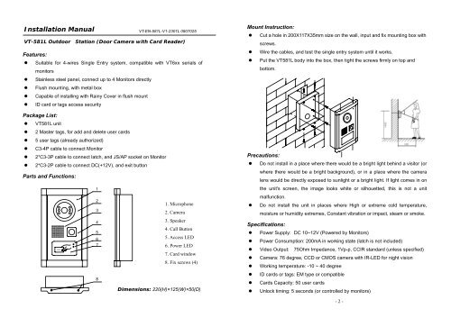
VT-581L Outdoor Station (Door Camera with Card Reader)<br />
Features:<br />
• Suitable for 4-wires Single Entry system, compatible with VT6xx serials of<br />
monitors<br />
• Stainless steel panel, connect up to 4 Monitors directly<br />
• Flush mounting, with metal box<br />
• Capable of installing with Rainy Cover in flush mount<br />
• ID card or tags access security<br />
Package List:<br />
• VT581L unit<br />
• 2 Master tags, for add and delete user cards<br />
• 5 user tags (already authorized)<br />
• C3-4P cable to connect Monitor<br />
• 2*C3-3P cable to connect latch, and JS/AP socket on Monitor<br />
• 2*C3-2P cable to connect DC(+12V), and exit button<br />
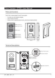
Parts and Functions:<br />
CARD<br />
1<br />
2<br />
3<br />
4<br />
5<br />
6<br />
7<br />
8<br />
VT-EN-581L-V1-2301L 0807025<br />
1. Microphone<br />
2. Camera<br />
3. Speaker<br />
4. Call Button<br />
5. Access LED<br />
6. Power LED<br />
7. Card window<br />
8. Fix screws (4)<br />
Dimensions: 220(H)×125(W)×50(D)<br />
Mount Instruction:<br />
• Cut a hole in 200X117X35mm size on the wall, input and fix mounting box with<br />
screws.<br />
• Wire the cables, and test the single entry system until it works.<br />
• Put the VT581L body into the box, then tight the screws firmly on top and<br />
bottom.<br />
Precautions:<br />
• Do not install in a place where there would be a bright light behind a visitor (or<br />
where there would be a bright background), or in a place where the camera<br />
lens would be directly exposed to sunlight or a bright light. If light comes in on<br />
the unit's screen, the image looks white or silhouetted, this is not a unit<br />
malfunction.<br />
• Do not install the unit in places where High or extreme cold temperature,<br />
moisture or humidity extremes, Constant vibration or impact, steam or smoke.<br />
Specifications:<br />
• Power Supply: DC 10~12V (Powered by Monitors)<br />
• Power Consumption: 200mA in working state (latch is not included)<br />
• Video Output: 75Ohm Impedance, 1Vp-p, CCIR standard (unless specified)<br />
• Camera: 76 degree, CCD or CMOS camera with IR-LED for night vision<br />
• Working temperature: -10 ~ 40 degree<br />
• ID cards or tags: EM type or compatible<br />
• Cards Capacity: 50 user cards<br />
• Unlock timing: 5 seconds (or controlled by monitors)<br />
- 2 -
Wiring Terminals on VT581L<br />
Wiring Diagram 1 (VT581L is powered by Monitor)<br />
Illustration of VT581L PCB Board<br />
5<br />
JP-VD<br />
JP-LK<br />
CN101<br />
DC-<br />
DC+<br />
1R<br />
2W<br />
3Y<br />
4B<br />
JS/VP<br />
JS-OS1<br />
1R<br />
2W<br />
3Y<br />
4B<br />
CAR<br />
D<br />
1R<br />
2W<br />
3Y<br />
4B<br />
JS/AP<br />
JS-OS2<br />
4B<br />
2W<br />
+12<br />
+12<br />
Red<br />
White<br />
Yellow<br />
Black<br />
White<br />
Black<br />
+12<br />
Red<br />
White<br />
Yellow<br />
Black<br />
1R<br />
2W<br />
3Y<br />
4B<br />
Wiring Diagram 2 (VT581L is powered by Additional +12V Adaptor)<br />
Terminals description<br />
• JS/DC: Connect to JS/AP on the Monitor, or external +12V Power Supply<br />
• JS/VP: Connect to JS/VP on the Monitor<br />
• JS/EB: Connect to external Exit Button<br />
• LB: Connect to latch (Dry Contact Mode)<br />
• LC: Connect to latch (DC output Mode)<br />
• JP/LS: Must be taken off if external Power Supply for latch is used<br />
• SET Jumper: Reserved, always set to right<br />
• ADD Jumper: If two VT581L are installed, set ADD to right for 2nd VT581L<br />
• PROG Button: Button used to authorize master cards<br />
- 3 -<br />
- 4 -
Electronic Latch connecting instructions<br />
• Mode 1: With Monitor’s JP-LK Jumper (Dry contact)<br />
LB<br />
3<br />
2<br />
1<br />
3<br />
2<br />
1<br />
1,2: Normal-Open Contacts<br />
3,2: Normal-Closed Contacts<br />
+<br />
+<br />
POWER<br />
SUPPLY<br />
for Latch<br />
Extra power supply for latch must be<br />
installed, and nearly all kinds of electronic<br />
latch can be used.<br />
in this mode, you can continue talking and<br />
monitoring during unlock operation.<br />
Note: JP/LS Jumper must be taken off.<br />
• Mode 2: Without Monitor’s JP-LK Jumper (DC output)<br />
LC<br />
3<br />
2<br />
1<br />
3<br />
2<br />
1<br />
LC Pin 3: 12V Output<br />
LC pin 2: Do not connect<br />
LC pin 1: GND<br />
+<br />
If the latch (normally door Strike) rated<br />
voltage is DC 12V, and less than 500mA<br />
consumption. The Latch can be directly<br />
connect and powered by Monitor.<br />
During unlock operation, the monitor will<br />
close screen automatically.<br />
Note: JP/LS Jumper must be reserved.<br />
Operation Instructions<br />
The upper LED is for access indicator, and will light after a<br />
valid User card is shown. The bottom LED is for state indicator,<br />
normally light in red, and turns to orange during programming.<br />
There is a beeper inside VT581L, in working state:<br />
• If a valid user card is shown, long beep;<br />
• If a invalid card is shown, three short beep;<br />
CARD<br />
In programming state:<br />
• Enter Programming state, long beep with short beep;<br />
• Exit Programming state, two short beep;<br />
• For user cards authorization, long beep if adding successfully, two long beep<br />
if repeated, five short beep if the user cards are full (more than 50).<br />
How to Program User Cards<br />
The Master cards are necessary when you<br />
add or delete user cards.<br />
Please keep the Master cards carefully.<br />
• Add user cards<br />
Show the Master Card<br />
–ADD in standby.<br />
Note. LED will turns<br />
to orange, and beep<br />
sound.<br />
• Delete user cards<br />
Show the Master Card<br />
–DELETE in standby.<br />
Note. LED flashes in<br />
red and orange in turn,<br />
and beep sound.<br />
Show the cards to be<br />
added, one by one.<br />
Note. Long beep if add<br />
success, two long beep<br />
if repeated.<br />
Show the cards to be<br />
deleted, one by one.<br />
Note. Long beep after<br />
deleting operation.<br />
• Delete all user cards(Format operation)<br />
Show the Master Card<br />
–DELETE in standby.<br />
Note. LED flashes in<br />
red and orange in turn,<br />
and beep sound.<br />
Show the Master Card<br />
–ADD to run format<br />
operation.<br />
MASTER<br />
CARD<br />
ADD<br />
MASTER<br />
CARD<br />
DELETE<br />
Show the Master Card<br />
–ADD again to exit.<br />
However, will exit if<br />
no card was showed<br />
within 15s.<br />
Show the Master Card<br />
–DELETE again to<br />
exit. However, will<br />
exit if no card was<br />
showed within 15s.<br />
Show the Master Card<br />
–ADD again to<br />
confirm the Format<br />
operation.<br />
- 5 -<br />
- 6 -
Program Instructions (Operate through Monitor)<br />
• Refer the Monitor manual to enter SETUP MENU, select INSTALLATION…, then<br />
input password, you will see the <strong>Installation</strong> Menu on the Screen.<br />
• Select ADVANCED SET.. to enter, input 3# to add cards, and 4# to delete cards.<br />
• Please note, only 691/TC7, 692/TC7, 693/TC5 Monitors will support this<br />
operation.<br />
Program Instructions (Master Cards)<br />
• Authorize master card-ADD<br />
Press PROG button on<br />
the VT581LA PCB.<br />
Note. LED will turns<br />
to orange, and beep<br />
sound.<br />
Show the card to be<br />
authorized.<br />
Note. Will exit if press<br />
PROG again or after 5<br />
seconds<br />
Long beep if authorize<br />
correctly, and will exit<br />
automatically.<br />
Note. The old Master<br />
card will be replaced.<br />
• Authorize master card-DELETE<br />
Keep pressing PROG<br />
button for 2seconds on<br />
Show the card to be<br />
authorized.<br />
Long beep if authorize<br />
correctly, and will exit<br />
The design and specifications can be changed without notice to the user.<br />
Right to interpret and copyright of this manual are preserved.<br />
the VT581LA PCB.<br />
Note. Will exit if press<br />
automatically.<br />
Note. LED flashes in<br />
PROG again or after 5<br />
Note. The old Master<br />
red and orange in turn,<br />
and beep sound.<br />
seconds<br />
card will be replaced.<br />
VT-EN-581L-V1-2301L<br />
- 7 -