DT-CONFIG SOFTWARE USER'S MANUAL - Schick Handel
DT-CONFIG SOFTWARE USER'S MANUAL - Schick Handel
DT-CONFIG SOFTWARE USER'S MANUAL - Schick Handel

Create successful ePaper yourself
Turn your PDF publications into a flip-book with our unique Google optimized e-Paper software.
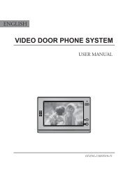
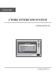
<strong>DT</strong>-<strong>CONFIG</strong> <strong>SOFTWARE</strong>USER’S <strong>MANUAL</strong>Video-Tech reserves the rights for future changes in the contents of this Manual without previousnotice due to our continuous improvement policy.
<strong>DT</strong>-<strong>CONFIG</strong> (DMR11) <strong>SOFTWARE</strong> USER’S <strong>MANUAL</strong>CONTENTS1. Introductions ------------------------------------------------------------------- 32. System Requirement and Connection ---------------------------------------- 33. Software Installation3.1. Install Software Package ------------------------------------------------------------- 43.2. Install The USB To RS485 Converter Hardware Driver ----------------------------- 63.3. Get The COM Port Number ---------------------------------------------------------- 113.4. Start <strong>DT</strong>-<strong>CONFIG</strong> and Setup the COM Port ----------------------------------------- 124. Connect A Door Station -------------------------------------------------------- 135. General Overview Of <strong>DT</strong>-<strong>CONFIG</strong> Software5.1. Main Menu --------------------------------------------------------------------------- 145.2. Parameter Setup --------------------------------------------------------------------- 155.3. NameList Setup --------------------------------------------------------------------- 166. Access Control Settings --------------------------------------------------------- 187. Use <strong>DT</strong>-<strong>CONFIG</strong> As Debug Tools7.1. Debug Tool -------------------------------------------------------------------------- 197.2. Trace Tool ---------------------------------------------------------------------------- 20Appendix. Print document Of A Sample Installation ---------------------------- 21<strong>DT</strong>-<strong>CONFIG</strong> Manual_V1 200912032
1. Introductions<strong>DT</strong>-<strong>CONFIG</strong> (DMR11) <strong>SOFTWARE</strong> USER’S <strong>MANUAL</strong><strong>DT</strong>-<strong>CONFIG</strong> software is a powerful configuration and debug tool to setup the 2-wire system.As simplified software tool, <strong>DT</strong>-<strong>CONFIG</strong> allows installers to check and program DoorStations rapidly, which is especially useful in complex installation.<strong>DT</strong>-<strong>CONFIG</strong> allows you to view device properties, modify parameters, re-locate CallButtons mapping and establish Name List in a PC and then download to the Door Station.Furthermore, you can use <strong>DT</strong>-<strong>CONFIG</strong> as a assistance in field debug and maintains, bymeans of printing Programming Table, online search and diagnose tools.<strong>DT</strong>-<strong>CONFIG</strong> contains a project management utility, which helps installers manage projectand device information.2. System Requirement and Connection<strong>DT</strong>-<strong>CONFIG</strong> can be installed in a PC or laptop with Microsoft Windows XP, VISTA, Server2003 or Server 2008 operating system, and at least 512M memory, and 100M free harddisc space. Please note, a spare USB2.0 port is necessary to connect interface converter.Note .The Monitors in above diagram are not necessary.USB2.0 to RS485 interface converter is packaged in <strong>DT</strong> accessory box.3
<strong>DT</strong>-<strong>CONFIG</strong> (DMR11) <strong>SOFTWARE</strong> USER’S <strong>MANUAL</strong>3. Software installation3.1. Install the software package3.1.1. Insert the software CD, double click the setup.exe file (Windows will automatically runsetup, if your PC auto run option isn’t disabled), to launch the install process.3.1.2. Fill the User Name and Company Name information.4
<strong>DT</strong>-<strong>CONFIG</strong> (DMR11) <strong>SOFTWARE</strong> USER’S <strong>MANUAL</strong>3.1.3. Use default install path, or change the path if needed, then click Next button.3.1.4. confirm to start installation.3.1.5. After the installation is finished, confirm and exit.5
<strong>DT</strong>-<strong>CONFIG</strong> (DMR11) <strong>SOFTWARE</strong> USER’S <strong>MANUAL</strong>3.2. Install the USB to RS485 converter hardware driverThis is very important step, must be careful to make surethe converter has been installed correctly.Please note, in this step, you don’t need to connect withthe Door Station, use converter alone.3.2.1. Connect the USB to RS485 converter to your PC USBport. Wait 5 seconds or more, Windows system will show that a new hardware is found.3.2.2. Select the last item ‘No , not this time’, then chick Next button.6
<strong>DT</strong>-<strong>CONFIG</strong> (DMR11) <strong>SOFTWARE</strong> USER’S <strong>MANUAL</strong>3.2.3. Select ‘Install from a list or specific location (Advanced)’, then click Next button3.2.4. Select ‘Include this location in the search’, then click Browse button.3.2.5. Select the ‘USB-485 Convertor Drive’ of <strong>DT</strong>-<strong>CONFIG</strong> software install path, then click OKbutton.7
<strong>DT</strong>-<strong>CONFIG</strong> (DMR11) <strong>SOFTWARE</strong> USER’S <strong>MANUAL</strong>3.2.6. After the browse operation, click Next button.3.2.7. Windows will indicate the Wizard has been completed, then click Finish button.After 4.2.1 to 4.2.7 operation, you have installed the USB Serial Converts.In the next steps, you will install USB Serial Port, similar with previous.8
<strong>DT</strong>-<strong>CONFIG</strong> (DMR11) <strong>SOFTWARE</strong> USER’S <strong>MANUAL</strong>3.2.8. Wait a few seconds, Windows will show a new USB Serial Port is found, select andoperate as previous steps. Firstly, Select ‘Install from a list or specific location(Advanced)’, then click Next button.3.2.9. Select ‘Include this location in the search’, then click Browse button.9
<strong>DT</strong>-<strong>CONFIG</strong> (DMR11) <strong>SOFTWARE</strong> USER’S <strong>MANUAL</strong>3.2.10. Select the ‘USB-485 Convertor Drive’ of <strong>DT</strong>-<strong>CONFIG</strong> software install path, then click OK button.3.2.11. After the browse operation, click Next button.After 4.2.8 to 4.2.11 operation, you have installed the USB Serial Port.By now, the USB converter related drivers have been installed.10
3.3. Get Te COM Port Number<strong>DT</strong>-<strong>CONFIG</strong> (DMR11) <strong>SOFTWARE</strong> USER’S <strong>MANUAL</strong>3.3.1. Operate as ‘Start->My Computer’, by right click on mouse, then select ‘Manage’, tolaunch ‘Computer Management’3.3.2. Locate Device Manager, and click and expand ‘Ports (COM & LPT)’, you will find the‘USB Serial Port (COM?)’ item. Please note, in different PC, the COM number isdifferent, just remember it, this information will be used for next step.11
<strong>DT</strong>-<strong>CONFIG</strong> (DMR11) <strong>SOFTWARE</strong> USER’S <strong>MANUAL</strong>3.4. Start <strong>DT</strong>-<strong>CONFIG</strong> and Setup The COM Port3.4.1. Run <strong>DT</strong>-<strong>CONFIG</strong> softwareCOM PORT ICON3.4.2. Select ‘Setting COM Setting’, and select the COM port which was found in 3.3.23.4.3. After the correct COM port has been selected, the COM PORT ICON will stop flashing.This ICON means the USB to RS485 converter has been connected.12
<strong>DT</strong>-<strong>CONFIG</strong> (DMR11) <strong>SOFTWARE</strong> USER’S <strong>MANUAL</strong>5. General Overview Of <strong>DT</strong>-<strong>CONFIG</strong> Software5.1. Main MenuMain Menus• File menu includes all project operations, such as New, Open, Save, Save As and Exit.• Setting menu includes Com Setting and Language (Not included in Demo version).• Refer Help menu for help contents.Information (Read/Upload from connected Door Station, can’t be changed)• Product Model, Hardware Version, Software Version, Serial, Access Control, AccessCard Number, Work Voltage, Standby Voltage.Note. Serial is a unique number programmed in assemble line and used for trackingUpload ButtonUpload function will read the connected Door Station information, including the following:• Information on property page, and Parameters listed on Parameter page• Panel models, Call Button mapping, Room Number and Name table on NameList page.After upload operation, the result will be showed as below.14
5.2. Parameter Setup<strong>DT</strong>-<strong>CONFIG</strong> (DMR11) <strong>SOFTWARE</strong> USER’S <strong>MANUAL</strong>Items Descriptions DefaultMonitor Timing From 6s to 600s. To set Limitation of Monitoring operation. 30 sCamera SwitchTimingWait TimingFrom 6s to 600s. When multi Door Stations are installed, setthe Monitoring time of this Door Station, and will be switchedto next Door Station after this time.From 10s to 600s.To set call wait and ring time, if Monitordon’t answer a call within this time, calling will be canceled.40 s30 sTalk Timing From 10s to 600s. To set Limitation of talking operation. 90 sUnlock TimingMon SpeakMon UnlockUnlock RelayRing NumbersFrom 1s to 99s. To set the time that how long the door keepsopen when lock is released.To enable Monitor under monitoring state can speak to DoorStation at same time. This option can be enabled/disabled.To enable Monitor under monitoring state can open the doorat same time. This option can be None (disabled); and other3 options all support open door operation, but with differentclose timing Support, None Delay (Close the Monitor afterunlock), Delay 5s (Close the Monitor, 5s after unlock).To select the unlock relay dry contact type, for different locktypes. This option can set to Normally Open or Close.To select the ring mode: ring once, ring twice, ring thrice andcycle ring.5 sEnabledSupportNormally OpenRing OnceRestore to default ButtonThis operation will retrieve default value of listed parameters.Download Parameter ButtonThis operation will download all the parameters on this page to connected Door Station.15
5.3. NameList Setup<strong>DT</strong>-<strong>CONFIG</strong> (DMR11) <strong>SOFTWARE</strong> USER’S <strong>MANUAL</strong>Panel ConfigurationTo select the Door Station and Expanded Panel combination in a specific entrance. Please notethe total Call Buttons are limited to 32. If Cancel Button and Manage Button (Call Guard Unit)are needed, click [Control Button] check option, and then specify the Call Buttons to be used.If User Code of this entrance isn’t regularly arranged, set [Start User Code] if necessary.After above operations, press Auto Set button to create a User Code mapping.You can modify the User Code mapping if necessary. Also, you can click Clear Button Positionbutton to clear the mapping, and assign the Call Button by manual.User Code, Name List and DIP Programming informationEdit the grids to fill Room No and Name Label, please note limitation less than 20 chars.You can sort the table by Room No, or by Name Label. Use Download Button Position button todownload Call Buttons mapping to connected Door Station.After editing, you can export the Name Label and User Code information to TXT file, so as tocreate a printable name label file, which can be used to replace the Door Station name labels.Download NameList informationIn 2-wire <strong>DT</strong> system, Monitors will display a intercom NameList menu for intercom calling. Thisname dictionary is transmitted from Door Station, and should be previously downloaded from<strong>DT</strong>-<strong>CONFIG</strong> software. After editing NameList information in software, press DownloadNameList to save into Door Station. In field installation, when Monitors are installed, use DoorStation PA button to transmit name dictionary to Monitors, see technical manual for reference.16
<strong>DT</strong>-<strong>CONFIG</strong> (DMR11) <strong>SOFTWARE</strong> USER’S <strong>MANUAL</strong>Print User Code programming tableUse Print Button to print a field programming reference document, it is much useful ininstallation and after-installation service.Part of printing job as below, including configuration and reference table:… …17
6. Assess Control settings<strong>DT</strong>-<strong>CONFIG</strong> (DMR11) <strong>SOFTWARE</strong> USER’S <strong>MANUAL</strong>Device OperationThis page includes all the Card operations in the device: Backup to File, Restore From File,Add Card, Delete Card, View Card, Clear Card, Setup Mater.File OperationIn this tab you can manage the file that include all the card information. You can edit the file tochange the information, such as add/delete user cards to a specific User Code to the exits file,clear all card register information, and then update to the device or save the file as a backup.18
<strong>DT</strong>-<strong>CONFIG</strong> (DMR11) <strong>SOFTWARE</strong> USER’S <strong>MANUAL</strong>7. Use <strong>DT</strong>-<strong>CONFIG</strong> As Debug Tools7.1. Debug ToolUser Code RangeTo change the User Code start and end address, only set valid range will save more time.Online Check ButtonUse this button to start Online searching, and the result will be showed in list window.Online search function is designed for the purpose of getting a quick view of the Monitorsinstalling situations, or to check if each of them works or not. This is very useful for installationmaintain.Diagnose ButtonUse this button to start Diagnose operation, and the result will be showed in list window.Diagnose operation will check the Monitor’s working voltage and standby voltage, video signalpresentence, and data communication.By means of this tool, if a Monitor passes the test, generally this Monitor should works well.Print ButtonTo print the debug result window information, for installation delivery documentation or memo.Export ButtonBy means of this tool, if a Monitor passes the test, generally this Monitor should works well.To export the debug result window information, you can analyze it in EXCEL sheet.19
<strong>DT</strong>-<strong>CONFIG</strong> (DMR11) <strong>SOFTWARE</strong> USER’S <strong>MANUAL</strong>7.2. Trace ToolAbout traceTRACE tool will display all data communication information presented on 2-wire BUS, whichcan be a high-end tool used by expertise to check the system stability, or locate the problemmore easily in a complex installation.Please note, it is not suitable for normal installers, as the data streams are complex.However, installers can send back the trace log, thus the engineers can analyze and help.Start Trace ButtonTo initiate and start trace operation, when system works, result will be automatically send backand displayed in log window.Stop Trace ButtonTo stop trace operation.Clear Trace ButtonTo clear the log listed in window, when you need to trace a new operation, it is useful.Print ButtonTo print the log listed in the result window.Export ButtonTo export the log listed in the result window to a TXT file. When you need to send back the tracelog, or analyze in EXCEL sheet, you should export the log first, then open it in EXCEL.20
<strong>DT</strong>-<strong>CONFIG</strong> (DMR11) <strong>SOFTWARE</strong> USER’S <strong>MANUAL</strong>Print Document of a sample installation - 222
<strong>DT</strong>-<strong>CONFIG</strong> (DMR11) <strong>SOFTWARE</strong> USER’S <strong>MANUAL</strong>Print Document of a sample installation - 323
<strong>DT</strong>-<strong>CONFIG</strong> (DMR11) <strong>SOFTWARE</strong> USER’S <strong>MANUAL</strong>Print Document of a sample installation - 424