IVS Drive RFI and Harmonics Info - Armstrong Pumps
IVS Drive RFI and Harmonics Info - Armstrong Pumps
IVS Drive RFI and Harmonics Info - Armstrong Pumps

You also want an ePaper? Increase the reach of your titles
YUMPU automatically turns print PDFs into web optimized ePapers that Google loves.
<strong>IVS</strong> 102 Design Guide 2 Introduction to <strong>IVS</strong> 102<br />
2.9 General Aspects of EMC<br />
2.9.1 General Aspects of EMC Emissions<br />
Electrical interference is usually conducted at frequences in the range 150 kHz to 30 MHz. Airborne interference from the drive system in the range 30<br />
MHz to 1 GHz is generated from the inverter, motor cable, <strong>and</strong> the motor.<br />
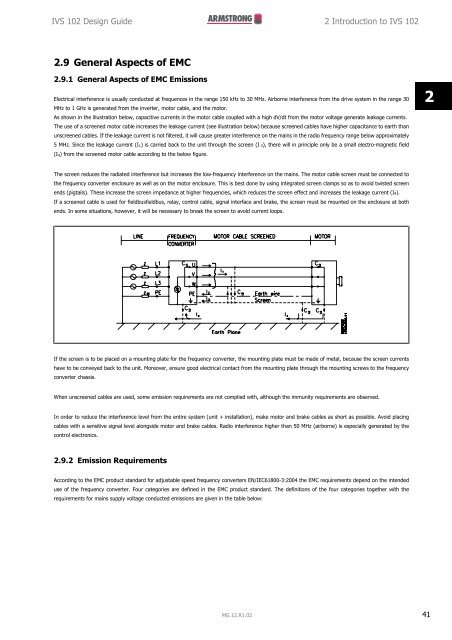
As shown in the illustration below, capacitive currents in the motor cable coupled with a high dV/dt from the motor voltage generate leakage currents.<br />
The use of a screened motor cable increases the leakage current (see illustration below) because screened cables have higher capacitance to earth than<br />
unscreened cables. If the leakage current is not filtered, it will cause greater interference on the mains in the radio frequency range below approximately<br />
5 MHz. Since the leakage current (I1) is carried back to the unit through the screen (I 3), there will in principle only be a small electro-magnetic field<br />
(I4) from the screened motor cable according to the below figure.<br />
2<br />
The screen reduces the radiated interference but increases the low-frequency interference on the mains. The motor cable screen must be connected to<br />
the frequency converter enclosure as well as on the motor enclosure. This is best done by using integrated screen clamps so as to avoid twisted screen<br />
ends (pigtails). These increase the screen impedance at higher frequencies, which reduces the screen effect <strong>and</strong> increases the leakage current (I4).<br />
If a screened cable is used for fieldbusfieldbus, relay, control cable, signal interface <strong>and</strong> brake, the screen must be mounted on the enclosure at both<br />
ends. In some situations, however, it will be necessary to break the screen to avoid current loops.<br />
If the screen is to be placed on a mounting plate for the frequency converter, the mounting plate must be made of metal, because the screen currents<br />
have to be conveyed back to the unit. Moreover, ensure good electrical contact from the mounting plate through the mounting screws to the frequency<br />
converter chassis.<br />
When unscreened cables are used, some emission requirements are not complied with, although the immunity requirements are observed.<br />
In order to reduce the interference level from the entire system (unit + installation), make motor <strong>and</strong> brake cables as short as possible. Avoid placing<br />
cables with a sensitive signal level alongside motor <strong>and</strong> brake cables. Radio interference higher than 50 MHz (airborne) is especially generated by the<br />
control electronics.<br />
2.9.2 Emission Requirements<br />
According to the EMC product st<strong>and</strong>ard for adjustable speed frequency converters EN/IEC61800-3:2004 the EMC requirements depend on the intended<br />
use of the frequency converter. Four categories are defined in the EMC product st<strong>and</strong>ard. The definitions of the four categories together with the<br />
requirements for mains supply voltage conducted emissions are given in the table below:<br />
MG.12.R1.02 41
2 Introduction to <strong>IVS</strong> 102 <strong>IVS</strong> 102 Design Guide<br />
Conducted emission requirement<br />
Category<br />
Definition<br />
according to the limits given in<br />
EN55011<br />
2<br />
C1<br />
C2<br />
frequency converters installed in the first environment (home <strong>and</strong> office) with a supply<br />
voltage less than 1000 V.<br />
frequency converters installed in the first environment (home <strong>and</strong> office) with a supply<br />
voltage less than 1000 V, which are neither plug-in nor movable <strong>and</strong> are intended to be<br />
Class B<br />
Class A Group 1<br />
installed <strong>and</strong> commissioned by a professional.<br />
C3<br />
frequency converters installed in the second environment (industrial) with a supply volt-<br />
Class A Group 2<br />
age lower than 1000 V.<br />
C4<br />
frequency converters installed in the second environment with a supply voltage equal to<br />
No limit line.<br />
or above 1000 V or rated current equal to or above 400 A or intended for use in complex<br />
An EMC plan should be made.<br />
systems.<br />
When the generic emission st<strong>and</strong>ards are used the frequency converters are required to comply with the following limits:<br />
Environment<br />
First environment<br />
(home <strong>and</strong> office)<br />
Second environment<br />
(industrial environment)<br />
Conducted emission requirement according<br />
to the limits given in<br />
Generic st<strong>and</strong>ard<br />
EN55011<br />
EN/IEC61000-6-3 Emission st<strong>and</strong>ard for residential, commercial <strong>and</strong><br />
Class B<br />
light industrial environments.<br />
EN/IEC61000-6-4 Emission st<strong>and</strong>ard for industrial environments. Class A Group 1<br />
2.9.3 EMC Test Results (Emission)<br />
The following test results have been obtained using a system with a frequency converter (with options if relevant), a screened control cable, a<br />
control box with potentiometer, as well as a motor <strong>and</strong> motor screened cable.<br />
<strong>RFI</strong> filter type<br />
Conducted emission.<br />
Radiated emission<br />
Maximum shielded cable length.<br />
Industrial environment Housing, trades<br />
<strong>and</strong> light industries<br />
Industrial environment<br />
Housing, trades <strong>and</strong><br />
light industries<br />
St<strong>and</strong>ard<br />
EN 55011 Class<br />
A2<br />
EN 55011<br />
Class A1<br />
EN 55011 Class B EN 55011 Class A1<br />
EN 55011 Class B<br />
H1<br />
1.1-45 kW 200-240 V T2 150 m 150 m 50 m Yes No<br />
1.1-90 kW 380-480 V T4 150 m 150 m 50 m Yes No<br />
H2<br />
1.1-3.7 kW 200-240 V T2 5 m No No No No<br />
5.5-45 kW 200-240 V T2 25 m No No No No<br />
1.1-7.5 kW 380-480 V T4 5 m No No No No<br />
11-90 kW 380-480 V T4 25 m No No No No<br />
110-1000 kW 380-480 V T4 150 m No No No No<br />
45-1400 kW 525-690 V T7 150 m No No No No<br />
H3<br />
1.1-45 kW 200-240 V T2 75 m 50 m 10 m Yes No<br />
1.1-90 kW 380-480 V T4 75 m 50 m 10 m Yes No<br />
H4<br />
110-1000 kW 380-480 V T4 150 m 150 m No Yes No<br />
45-400 kW 525-690 V T7 150 m 30 m No No No<br />
Hx<br />
1.1-90 kW 525-600 V T6 - - - - -<br />
Table 2.1: EMC Test Results (Emission)<br />
HX, H1, H2 or H3 is defined in the type code pos. 16 - 17 for EMC filters<br />
HX - No EMC filters build in the frequency converter (600 V units only)<br />
H1 - Integrated EMC filter. Fulfil Class A1/B<br />
H2 - No additional EMC filter. Fulfil Class A2<br />
H3 - Integrated EMC filter. Fulfil class A1/B (Frame size A1 only)<br />
H4 - Integrated EMC filter. Fulfil class A1<br />
42 MG.12.R1.02
<strong>IVS</strong> 102 Design Guide 2 Introduction to <strong>IVS</strong> 102<br />
2.9.4 General Aspects of <strong>Harmonics</strong> Emission<br />
A frequency converter takes up a non-sinusoidal current from mains,<br />
which increases the input current IRMS. A non-sinusoidal current is transformed<br />
by means of a Fourier analysis <strong>and</strong> split up into sine-wave<br />
currents with different frequencies, i.e. different harmonic currents I N<br />
with 50 Hz as the basic frequency:<br />
Harmonic currents I1 I5 I7<br />
Hz 50 Hz 250 Hz 350 Hz<br />
2<br />
The harmonics do not affect the power consumption directly but increase<br />
the heat losses in the installation (transformer, cables). Consequently, in<br />
plants with a high percentage of rectifier load, maintain harmonic currents<br />
at a low level to avoid overload of the transformer <strong>and</strong> high<br />
temperature in the cables.<br />
NB!<br />
Some of the harmonic currents might disturb communication equipment connected to the same transformer or cause resonance in<br />
connection with power-factor correction batteries.<br />
To ensure low harmonic currents, the frequency converter is equipped with intermediate circuit coils as st<strong>and</strong>ard. This normally reduces the input current<br />
I RMS by 40%.<br />
The voltage distortion on the mains supply voltage depends on the size of the harmonic currents multiplied by the mains impedance for the frequency<br />
in question. The total voltage distortion THD is calculated on the basis of the individual voltage harmonics using this formula:<br />
THD % =<br />
U 2 5 + U 2 7 + ... + U 2 N<br />
(UN% of U)<br />
2.9.5 <strong>Harmonics</strong> Emission Requirements<br />
Equipment connected to the public supply network:<br />
Options: Definition:<br />
1 IEC/EN 61000-3-2 Class A for 3-phase balanced equipment<br />
(for professional equipment only up to 1 kW total<br />
power).<br />
2 IEC/EN 61000-3-12 Equipment 16A-75A <strong>and</strong> professional<br />
equipment as from 1 kW up to 16A phase current.<br />
2.9.6 <strong>Harmonics</strong> Test Results (Emission)<br />
Power sizes up to PK75 in T2 <strong>and</strong> T4 complies with IEC/EN 61000-3-2 Class A. Power sizes from P1K1 <strong>and</strong> up to P18K in T2 <strong>and</strong> up to P90K in T4 complies<br />
with IEC/EN 61000-3-12, Table 4. Power sizes P110 - P450 in T4 also complies with IEC/EN 61000-3-12 even though not required because currents are<br />
above 75 A.<br />
Provided that the short-circuit power of the supply Ssc is greater than or equal to:<br />
S SC<br />
=<br />
3 × R SCE<br />
× U mains<br />
× I equ<br />
= 3 × 120 × 400 × I equ<br />
at the interface point between the user’s supply <strong>and</strong> the public system (Rsce).<br />
It is the responsibility of the installer or user of the equipment to ensure, by consultation with the distribution network operator if necessary, that the<br />
equipment is connected only to a supply with a short-circuit power Ssc greater than or equal to specified above.<br />
MG.12.R1.02 43
2 Introduction to <strong>IVS</strong> 102 <strong>IVS</strong> 102 Design Guide<br />
Other power sizes can be connected to the public supply network by consultation with the distribution network operator.<br />
2<br />
Compliance with various system level guidelines:<br />
The harmonic current data in the table are given in accordance with IEC/EN61000-3-12 with reference to the Power <strong>Drive</strong> Systems product st<strong>and</strong>ard.<br />
They may be used as the basis for calculation of the harmonic currents' influence on the power supply system <strong>and</strong> for the documentation of compliance<br />
with relevant regional guidelines: IEEE 519 -1992; G5/4.<br />
2.9.7 Immunity Requirements<br />
The immunity requirements for frequency converters depend on the environment where they are installed. The requirements for the industrial environment<br />
are higher than the requirements for the home <strong>and</strong> office environment. All <strong>Armstrong</strong> frequency converters comply with the requirements for the industrial<br />
environment <strong>and</strong> consequently comply also with the lower requirements for home <strong>and</strong> office environment with a large safety margin.<br />
In order to document immunity against electrical interference from electrical phenomena, the following immunity tests have been made on a system<br />
consisting of a frequency converter (with options if relevant), a screened control cable <strong>and</strong> a control box with potentiometer, motor cable <strong>and</strong> motor.<br />
The tests were performed in accordance with the following basic st<strong>and</strong>ards:<br />
• EN 61000-4-2 (IEC 61000-4-2): Electrostatic discharges (ESD): Simulation of electrostatic discharges from human beings.<br />
• EN 61000-4-3 (IEC 61000-4-3): Incoming electromagnetic field radiation, amplitude modulated simulation of the effects of radar <strong>and</strong> radio<br />
communication equipment as well as mobile communications equipment.<br />
• EN 61000-4-4 (IEC 61000-4-4): Burst transients: Simulation of interference brought about by switching a contactor, relay or similar devices.<br />
• EN 61000-4-5 (IEC 61000-4-5): Surge transients: Simulation of transients brought about e.g. by lightning that strikes near installations.<br />
• EN 61000-4-6 (IEC 61000-4-6): RF Common mode: Simulation of the effect from radio-transmission equipment joined by connection cables.<br />
See following EMC immunity form.<br />
EMC immunity form<br />
Voltage range: 200-240 V, 380-480 V<br />
Basic st<strong>and</strong>ard<br />
Burst<br />
IEC 61000-4-4<br />
Surge<br />
IEC 61000-4-5<br />
ESD<br />
IEC<br />
61000-4-2<br />
Radiated electromagnetic field<br />
IEC 61000-4-3<br />
RF common<br />
mode voltage<br />
IEC 61000-4-6<br />
Acceptance criterion B B B A A<br />
Line<br />
2 kV/2 Ω DM<br />
4 kV CM<br />
4 kV/12 Ω CM<br />
— — 10 VRMS<br />
Motor 4 kV CM 4 kV/2 Ω 1) — — 10 VRMS<br />
Brake 4 kV CM 4 kV/2 Ω 1) — — 10 VRMS<br />
Load sharing 4 kV CM 4 kV/2 Ω 1) — — 10 VRMS<br />
Control wires 2 kV CM 2 kV/2 Ω 1) — — 10 VRMS<br />
St<strong>and</strong>ard bus 2 kV CM 2 kV/2 Ω 1) — — 10 VRMS<br />
Relay wires 2 kV CM 2 kV/2 Ω 1) — — 10 VRMS<br />
Application <strong>and</strong> Fieldbus options<br />
2 kV CM<br />
2 kV/2 Ω 1) — — 10 VRMS<br />
LCP cable 2 kV CM 2 kV/2 Ω 1) — — 10 VRMS<br />
External 24 V DC<br />
0.5 kV/2 Ω DM<br />
2 kV CM<br />
1 kV/12 Ω CM<br />
— — 10 VRMS<br />
Enclosure<br />
8 kV AD<br />
— —<br />
6 kV CD<br />
10 V/m —<br />
AD: Air Discharge<br />
CD: Contact Discharge<br />
CM: Common mode<br />
DM: Differential mode<br />
1. Injection on cable shield.<br />
Table 2.2: Immunity<br />
44 MG.12.R1.02