ED 134A Instructions - Sea Frost Refrigeration
ED 134A Instructions - Sea Frost Refrigeration
ED 134A Instructions - Sea Frost Refrigeration

You also want an ePaper? Increase the reach of your titles
YUMPU automatically turns print PDFs into web optimized ePapers that Google loves.
148 OLD CONCORD TURNPIKE BARRINGTON, NH 03825 USA TEL (603) 868-5720 FAX (603) 868-1040 1-800-435-6708<br />
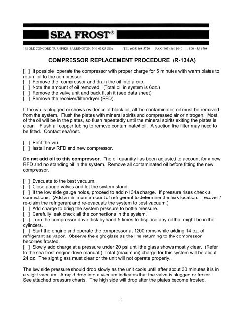
COMPRESSOR REPLACEMENT PROC<strong>ED</strong>URE (R-<strong>134A</strong>)<br />
[ ] If possible operate the compressor with proper charge for 5 minutes with warm plates to<br />
return oil to the compressor.<br />
[ ] Remove the compressor and drain the oil into a cup.<br />
[ ] Note the amount of oil removed. (Total oil in system is 6oz.)<br />
[ ] Remove the valve unit and back flush it (see data sheet)<br />
[ ] Remove the receiver/filter/dryer (RFD).<br />
If the v/u is plugged or shows evidence of black oil, all the contaminated oil must be removed<br />
from the system. Flush the plates with mineral spirits and compressed air or nitrogen. Most<br />
of the oil will be in the plates, so flush repeatedly until the mineral spirits exiting the plates is<br />
clean. Flush all copper tubing to remove contaminated oil. A suction line filter may need to<br />
be fitted. Contact seafrost.<br />
[ ] Refit the v/u.<br />
[ ] Install new RFD and new compressor.<br />
Do not add oil to this compressor. The oil quantity has been adjusted to account for a new<br />
RFD and no standing oil in the system. Remove all contaminated oil before fitting the new<br />
compressor.<br />
[ ] Evacuate to the best vacuum.<br />
[ ] Close gauge valves and let the system stand.<br />
[ ] If the low side gauge holds, proceed to add r-134a charge. If pressure rises check all<br />
connections. (Add a minimum amount of refrigerant to determine the leak location. recover /<br />
re-claim the refrigerant and re-evacuate the system to best vacuum.)<br />
[ ] Add charge to bring the system pressure to bottle pressure.<br />
[ ] Carefully leak check all the connections in the system.<br />
[ ] Turn the compressor drive disk by hand 5 times to displace any oil that might be in the<br />
cylinders.<br />
[ ] Start the engine and operate the compressor at 1200 rpms while adding 14 oz. of<br />
refrigerant as vapor. Observe the sight glass as the line returning to the compressor<br />
becomes frosted.<br />
[ ] Slowly add charge at a pressure under 20 psi until the glass shows mostly clear. (Refer<br />
to the sea frost engine drive manual.) Total (maximum) charge for this system will be about<br />
24 oz. The sight glass must clear or the unit will not operate properly.<br />
The low side pressure should drop slowly as the unit cools until after about 30 minutes it is in<br />
a slight vacuum. A rapid drop into a vacuum indicates that the valve is plugged or frozen.<br />
See attached pressure charts. The high side will drop after the plates become frosted.<br />
1
If the pressure exceeds 220 psi the high-pressure switch will disconnect the clutch and the<br />
lamp. If the unit cycles in the beginning of the cooling process it is over charged or operating<br />
with low cooling water flow (check engine water pump and strainer). The compressor cycling<br />
may stop after a few minutes, however cycling is an indication that the unit is operating at a<br />
higher than normal pressure. Do not allow the system to be operated in this overcharged<br />
state; doing so will cause excessive wear on the compressor.<br />
* Warm water pressures will be 140 to 170 on the high side.<br />
* Cold-water pressures will be under 100 on the high side.<br />
* Charging in cold water can overcharge the system causing the high pressure cut out to<br />
cycle as the water warms up later in the season or as the boat sails to southern waters.<br />
* Engine rpms, engine water pump size, and water temperature are all factors in the<br />
operating pressures of this system. Please call if you have questions or problems.<br />
Cleaning the valve unit (v/u)<br />
With the v/u in this position fill this fitting with clean paint thinner (mineral spirits). Make an<br />
adaptor from rubber hose to pressurize this fitting with compressed air. Use low air pressure<br />
(10 psi). High pressure will shut the valve.<br />
Sludge, dirt, and contaminants will blow out. Collect the contaminants in a clean cloth.<br />
Repeat this process several times until the mineral spirits comes out clean and there is<br />
airflow through the valve. Note: the valve is a restrictive device that will not pass the full<br />
volume of input<br />
2
air.<br />
3