Slowing and stopping light using an optomechanical crystal array
Slowing and stopping light using an optomechanical crystal array
Slowing and stopping light using an optomechanical crystal array

You also want an ePaper? Increase the reach of your titles
YUMPU automatically turns print PDFs into web optimized ePapers that Google loves.
12<br />
Required Input Power (mW)<br />
10<br />
9<br />
8<br />
7<br />
6<br />
5<br />
4<br />
3<br />
2<br />
1<br />
0<br />
-5 -4 -3 -2 -1 0 1 2 3 4<br />
0<br />
5<br />
(ω − ω )/κ<br />
2 ex<br />
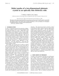
Figure 4. The input power (red line) required to achieve the system parameters<br />
used in the text, i.e. m /2π = 130 MHz with h/2π = 0.346 MHz, <strong><strong>an</strong>d</strong> the<br />
attenuation per unit cell α (solid black line) are shown as a function of detuning<br />
of the pump beam from the pump cavity frequency. The dotted line is the<br />
approximate expression derived for the attenuation, α ≈ κ ex κ in /4δk 2 . The gray<br />
region indicates the b<strong><strong>an</strong>d</strong> gap in which the pump cavities c<strong>an</strong>not be excited from<br />
the waveguide. The trade-off between small pump input powers <strong><strong>an</strong>d</strong> low pump<br />
attenuation factors is readily apparent in this plot.<br />
1.0<br />
0.9<br />
0.8<br />
0.7<br />
0.6<br />
0.5<br />
0.4<br />
0.3<br />
0.2<br />
0.1<br />
α<br />
or odd supermode of the double cavity, respectively. The waveguide width <strong><strong>an</strong>d</strong> proximity to the<br />
L2 cavities c<strong>an</strong> be used to tune the cavity loading (see the appendix), which for the structure<br />
in figure 3(a) results in the desired κ ex /2π = 2.4 GHz. It should be noted that these line-defect<br />
waveguides do not guide phonons at the frequency of Q − <strong><strong>an</strong>d</strong> thus no additional phonon leakage<br />
is induced in the localized mech<strong>an</strong>ical reson<strong>an</strong>ce.<br />
The full slow-<strong>light</strong> waveguide system consists of a periodic <strong>array</strong> of the double-cavity,<br />
double-waveguide structure. The numerically computed b<strong><strong>an</strong>d</strong> diagram, for spacing d = 15a<br />
periods of the snowflake lattice between cavity elements (the superlattice period), is shown in<br />
figure 3(d). This choice of superlattice period results in the folded superlattice b<strong><strong>an</strong>d</strong> intersecting<br />
the E − (â 1 ) cavity frequency ω 1 at roughly mid-zone, corresponding to the desired inter-cavity<br />
phase shift of kd = π/2. A zoom-in of the b<strong><strong>an</strong>d</strong>structure near the optical cavity reson<strong>an</strong>ces<br />
is shown in figures 3(e) <strong><strong>an</strong>d</strong> (f). In figure 3(e), the even parity supermode b<strong><strong>an</strong>d</strong>structure is<br />
plotted (i.e. assuming that the even supermode of the double waveguide is excited), whereas<br />
in figure 3(f) it is the odd parity supermode b<strong><strong>an</strong>d</strong>structure.<br />
A subtlety in the optical pumping of the periodically <strong>array</strong>ed waveguide system is that for<br />
the E + (â 2 ) optical cavity reson<strong>an</strong>ce at ω 2 , there exists a tr<strong>an</strong>smission b<strong><strong>an</strong>d</strong> gap. To populate<br />
cavity â 2 , then, <strong><strong>an</strong>d</strong> to create the polaritonic b<strong><strong>an</strong>d</strong> at ω 1 , the pump beam must be s<strong>light</strong>ly offreson<strong>an</strong>t<br />
from ω 2 , but still at ω 1 − ω m . We achieve this by choosing a double-cavity separation<br />
(14 periods) resulting in a cavity mode splitting ((ω 1 − ω 2 )/2π = 9.7 GHz) s<strong>light</strong>ly smaller th<strong>an</strong><br />
the mech<strong>an</strong>ical frequency (ω m /2π = 11.2 GHz), as shown in figures 3(e) <strong><strong>an</strong>d</strong> (f). By ch<strong>an</strong>ging<br />
the detuning between ω 1 − ω 2 <strong><strong>an</strong>d</strong> ω m , a trade-off c<strong>an</strong> be made between the attenuation of the<br />
pump beam per unit cell, α ≡ exp(−Im{K }d), <strong><strong>an</strong>d</strong> total required input power, shown in figure 4.<br />
In appendix D.3, we show that the total attenuation per unit cell is given by α ≈ κ ex κ in /4δ 2 k .<br />
New Journal of Physics 13 (2011) 023003 (http://www.njp.org/)