Slowing and stopping light using an optomechanical crystal array
Slowing and stopping light using an optomechanical crystal array
Slowing and stopping light using an optomechanical crystal array

Create successful ePaper yourself
Turn your PDF publications into a flip-book with our unique Google optimized e-Paper software.
22<br />
(a)<br />
14<br />
250<br />
(b) (c)<br />
13<br />
240<br />
W<br />
W<br />
a<br />
r<br />
ν (GHz)<br />
12<br />
11<br />
10<br />
ν m<br />
ν (THz)<br />
230<br />
220<br />
210<br />
200<br />
ν o<br />
(d)<br />
(e)<br />
w<br />
9<br />
8<br />
190<br />
180<br />
y<br />
7<br />
170<br />
x<br />
0 0.5 1<br />
k (π/d)<br />
0 0.5 1<br />
k (π/d)<br />
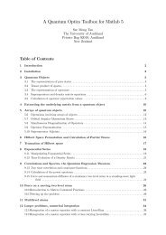
Figure E.1. (a) The snowflake waveguide consists of the usual snowflake lattice,<br />
with a removed row <strong><strong>an</strong>d</strong> adjusted waveguide width. The guiding region is shaded<br />
red for clarity. (b) The mech<strong>an</strong>ical b<strong><strong>an</strong>d</strong> structure exhibits a full phononic b<strong><strong>an</strong>d</strong><br />
gap at the reson<strong>an</strong>ce frequency of the mech<strong>an</strong>ical mode (ν m ). (c) The optical b<strong><strong>an</strong>d</strong><br />
structure exhibits a single b<strong><strong>an</strong>d</strong> that passes through the reson<strong>an</strong>ce frequency ν 0 of<br />
the optical mode. The waveguide acts as a single-mode optical waveguide with<br />
field pattern H z shown in (d). The H z component of the guided optical mode of<br />
opposite symmetry is shown in (e) for completeness.<br />
E.2. Properties of snowflake <strong>crystal</strong> waveguides<br />
A line defect on <strong>an</strong> OMC acts as a waveguide for <strong>light</strong> [40, 41]. Here, the line defects used<br />
consist of a removed row of holes, with the rows above <strong><strong>an</strong>d</strong> below shifted toward one <strong>an</strong>other<br />
by a dist<strong>an</strong>ce W , such that the dist<strong>an</strong>ce between the centers of the snowflakes across the line<br />
defect is √ 3a − 2W (see figure E.1(a)). The waveguide was designed such that mech<strong>an</strong>ically, it<br />
would have no b<strong><strong>an</strong>d</strong>s reson<strong>an</strong>t with the cavity frequency (see figure E.1(b)) <strong><strong>an</strong>d</strong> would therefore<br />
have no effect on the mech<strong>an</strong>ical Q factors. Optically, it was designed to have a single b<strong><strong>an</strong>d</strong><br />
crossing the cavity frequency (see figure E.1(c)) <strong><strong>an</strong>d</strong> would therefore serve as the single-mode<br />
optical waveguide required by the proposal. The b<strong><strong>an</strong>d</strong> structure of the mech<strong>an</strong>ical waveguide<br />
was calculated <strong>using</strong> COMSOL [42], while for the optical simulations, MPB [43] was used.<br />
E.3. Cavity–waveguide coupling<br />
By bringing the optical waveguide near our cavity, the guided modes of the line defect are<br />
ev<strong>an</strong>escently coupled to the cavity mode, <strong><strong>an</strong>d</strong> a coupling between the two may be induced, as<br />
shown in figure E.2(a). Control over this coupling rate is achieved at a coarse level by ch<strong>an</strong>ging<br />
the dist<strong>an</strong>ce between the cavity <strong><strong>an</strong>d</strong> the waveguide, i.e. the number of unit cells between them.<br />
New Journal of Physics 13 (2011) 023003 (http://www.njp.org/)