Slowing and stopping light using an optomechanical crystal array
Slowing and stopping light using an optomechanical crystal array
Slowing and stopping light using an optomechanical crystal array

You also want an ePaper? Increase the reach of your titles
YUMPU automatically turns print PDFs into web optimized ePapers that Google loves.
4<br />
(a)<br />
(b)<br />
a R (z)<br />
optical<br />
waveguide<br />
a R (z+d)<br />
a R (z)<br />
optical<br />
waveguide<br />
a R (z+d)<br />
a L (z)<br />
in<br />
ex<br />
a 1<br />
h<br />
b<br />
m<br />
a 2<br />
ex<br />
in<br />
a L (z+d)<br />
optical<br />
cavities<br />
mech<strong>an</strong>ical<br />
cavity<br />
a L (z)<br />
in<br />
ex<br />
a<br />
b<br />
m (t)<br />
a L (z+d)<br />
“active”<br />
optical<br />
cavity<br />
mech<strong>an</strong>ical<br />
cavity<br />
m<br />
1<br />
0.9<br />
0.8<br />
0.7<br />
0.6<br />
0.5<br />
0.4<br />
0.3<br />
0.2<br />
0.1<br />
(c)<br />
2<br />
|t| , Ω = 0<br />
2<br />
|r| , Ω = 0<br />
2<br />
|t| , Ω = κ/10<br />
2<br />
|r| , Ω = κ/10<br />
0<br />
-0.1 0 0.1<br />
0<br />
-3 -2 -1 0 1 2 3<br />
δ/κ<br />
1<br />
0.5<br />
(d)<br />
a R (z,t)<br />
|n , n<br />
m 1 ><br />
|n , n +<br />
m 1<br />
1><br />
m (t)<br />
|n + 1, n<br />
m 1><br />
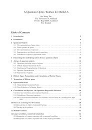
Figure 1. (a) Illustration of a double optical cavity system forming the unit<br />
cell of the optomech<strong>an</strong>ical <strong>array</strong>. A two-way optical waveguide is coupled to<br />
a pair of optical cavity modes a 1 <strong><strong>an</strong>d</strong> a 2 , whose reson<strong>an</strong>ce frequencies differ<br />
by the frequency of the mech<strong>an</strong>ical mode b. Both optical modes leak energy<br />
into the waveguide at a rate κ ex <strong><strong>an</strong>d</strong> have <strong>an</strong> inherent decay rate κ in . The<br />
mech<strong>an</strong>ical resonator optomech<strong>an</strong>ically couples the two optical reson<strong>an</strong>ces with<br />
a cross-coupling rate of h. (b) A simplified system diagram where the classically<br />
driven cavity mode a 2 is effectively eliminated to yield <strong>an</strong> optomech<strong>an</strong>ical<br />
driving amplitude m between the mech<strong>an</strong>ical mode <strong><strong>an</strong>d</strong> the cavity mode a 1 .<br />
(c) Frequency-dependent reflect<strong>an</strong>ce (black curve) <strong><strong>an</strong>d</strong> tr<strong>an</strong>smitt<strong>an</strong>ce (red) of<br />
a single <strong>array</strong> element, in the case of no optomech<strong>an</strong>ical driving amplitude<br />
m = 0 (dotted line) <strong><strong>an</strong>d</strong> <strong>an</strong> amplitude of m = κ ex /10 (solid line). The inherent<br />
cavity decay is chosen to be κ in = 0.1κ ex . (Inset) The optomech<strong>an</strong>ical coupling<br />
creates a tr<strong>an</strong>sparency window of width ∼4 2 m /κ ex for a single element <strong><strong>an</strong>d</strong><br />
enables perfect tr<strong>an</strong>smission on reson<strong>an</strong>ce, δ k = 0. (d) Energy level structure<br />
of the simplified system. The number of photons <strong><strong>an</strong>d</strong> phonons are denoted by<br />
n 1 <strong><strong>an</strong>d</strong> n m , respectively. The optomech<strong>an</strong>ical driving amplitude m couples<br />
states |n m + 1, n 1 〉 ↔ |n m , n 1 + 1〉, while the <strong>light</strong> in the waveguide couples states<br />
|n m , n 1 〉 ↔ |n m , n 1 + 1〉. The two couplings create a set of -type tr<strong>an</strong>sitions<br />
<strong>an</strong>alogous to that in EIT.<br />
New Journal of Physics 13 (2011) 023003 (http://www.njp.org/)