operating instructions manual for “k†dosing pump - A.T.A. srl
operating instructions manual for “k†dosing pump - A.T.A. srl
operating instructions manual for “k†dosing pump - A.T.A. srl

Create successful ePaper yourself
Turn your PDF publications into a flip-book with our unique Google optimized e-Paper software.
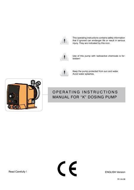
This <strong>operating</strong> <strong>instructions</strong> contains safety in<strong>for</strong>mation<br />
that if ignored can endanger life or result in serious<br />
injury. They are indicated by this icon.<br />
3<br />
2<br />
1 Use of this <strong>pump</strong> with radioactive chemicals is <strong>for</strong>bidden!<br />
D<br />
Keep the <strong>pump</strong> protected from sun and water.<br />
Avoid water splashes.<br />
O P E R A T I N G<br />
C<br />
I N S T R U C T I O N S<br />
MANUAL FOR “K” DOSING PUMP<br />
B<br />
Progettato da Controllato da Approvato da Data<br />
Data<br />
federico.renzi 21/05/2008<br />
A<br />
3<br />
2<br />
Edizione<br />
1<br />
Foglio<br />
1 / 1<br />
Read Carefully !<br />
ENGLISH Version<br />
R1-04-08 1
“K” series solenoid <strong>dosing</strong> <strong>pump</strong>s comply with the following European regulations:<br />
EN60335-1 : 1995, EN55014, EN50081-1/2, EN50082-1/2, EN6055-2, EN60555,3<br />
Based on directive CEE 73/23 c 93/68 (DBT Low voltage directive) and directive 89/336/<br />
CEE (EMC Electromagnetic Compatibility)<br />
GENERAL SAFETY GUIDELINES<br />
Danger!<br />
In emergencies the <strong>pump</strong> should be switched off immediately! Disconnect the power<br />
cable from the power supply!<br />
When using <strong>pump</strong> with aggressive chemicals observe the regulations concerning the<br />
transport and storage of aggressive fluids!<br />
When installing always observe national regulations!<br />
Manufacturer is not liable <strong>for</strong> any unauthorized use or misuse of this product that may<br />
cause injury, damage to persons or materials.<br />
Caution!<br />
Pump must be accessible at all times <strong>for</strong> both <strong>operating</strong> and servicing. Access must<br />
not be obstructed in any way!<br />
Feeder should be interlocked with a no-flow protection device.<br />
Pump and accessories must be serviced and repaired by qualified and authorized<br />
personnel only!<br />
Always discharge the liquid end be<strong>for</strong>e servicing the <strong>pump</strong>!<br />
Empty and rinse the liquid end be<strong>for</strong>e work on a <strong>pump</strong> which has been used with<br />
hazardous or unknown chemicals!<br />
Always read chemical safety datasheet!<br />
2<br />
Always wear protective clothing when handling hazardous or unknown chemicals!
1. Introduction<br />
Introduction:<br />
Metering Pumps “K” Series are the ideal solution <strong>for</strong> low / middle <strong>dosing</strong> of chemicals. All<br />
control and setup parameters are available through knobs and a visual system (led). Metering<br />
Pumps “K” Series have got an On/Off digital switch <strong>for</strong> ensure <strong>dosing</strong> activity (available only <strong>for</strong><br />
some models).<br />
Pump’s capacity<br />
Flow rate is determined by the stroke length and by the stroke speed. The stroke length is<br />
adjustable from 0 to 100% using the stroke length adjustment knob. However <strong>dosing</strong> accuracy<br />
is guarantee within an adjustment range from 30% to 100%. The led on the frontal panel shows the<br />
activity status of the <strong>pump</strong>.<br />
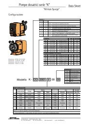
Models:<br />
KCO<br />
Constant <strong>pump</strong> with stroke speed (frequency) adjustment<br />
KCL<br />
Constant <strong>pump</strong> with level control, stroke speed (frequency) adjustment<br />
KIS<br />
Constant-proportional <strong>pump</strong> driven by external digital signal with level control: to<br />
each external pulse correspond one <strong>pump</strong> stroke<br />
KPV<br />
Constant-proportional <strong>pump</strong> driven by external digital signal with pulse divider mode<br />
(ratio 1 to 1000) and level control<br />
KPVM<br />
Constant-proportional <strong>pump</strong> driven by external digital signal, level control , with<br />
pulse divider mode (ratio 1 to 100) and multiplier mode (ratio 1 to 10)<br />
KIC Constant-proportional <strong>pump</strong> driven by current signal (0/4mA = 0 pulses; 20mA =<br />
max pulses) and level control<br />
Capacity:<br />
Pressure<br />
bar<br />
Flow<br />
l/h<br />
20 01<br />
18 02<br />
15 04<br />
10 05<br />
08 08<br />
05 10<br />
02 18<br />
Self venting capacity:<br />
Pressure<br />
bar<br />
Flow<br />
l/h<br />
18 01<br />
15 03<br />
10 3.5<br />
08 5.5<br />
05 7.5<br />
02 13<br />
3
2. Unpacking<br />
Included into package:<br />
n.4 Dibbles ø6<br />
n.4 Self tapping screws 4,5 x 40<br />
n.1 Fuse<br />
n.1 Foot filter with valve<br />
n.1 Injection valve<br />
n.1 Level probe<br />
m 2 Delivery pipe* (PVDF)<br />
m 2 Suction pipe * (transparent PVC)<br />
m 2 Discharge pipe (transparent PVC)<br />
n.1 This installation <strong>manual</strong><br />
* If hose is 6x8 there is only a 4meters long hose.<br />
Cut to obtain suction and delivery hoses.<br />
Remove the contents from the box.<br />
PLEASE DO NOT TRASH PACKAGING.<br />
IT CAN BE USED TO RETURN THE PUMP.<br />
4
3. Pump’s description<br />
* Stroke length Knob<br />
* Press to turn.<br />
To avoid <strong>pump</strong>’s damage, turn the knob<br />
when the <strong>pump</strong> is on.<br />
to discharge hose<br />
Delivery valve<br />
Pump head<br />
Level probe input<br />
External Signal input<br />
to power supply<br />
5
4. Be<strong>for</strong>e to Install warnings<br />
Pump’s installation and operativity is made in 4 main steps:<br />
Pump’s installation<br />
Hydraulic Installation (hoses, level probe, injection valve)<br />
Electrical Installation (main power connection, priming)<br />
Programming the <strong>pump</strong>.<br />
Be<strong>for</strong>e to start, please read carefully the following safety in<strong>for</strong>mation.<br />
Protective clothes<br />
Installation location<br />
Hoses and Valves<br />
Wear always protective clothes as masks, gloves, safety glasses and<br />
qfurther security devices during ALL installation procedure and while<br />
handling chemicals.<br />
Pump must be installed in a safety place and fixed to the table / wall to<br />
avoid vibration problems!<br />
Pump must be installed in a easy accessible place!<br />
Pump must be installed in horizontal position!<br />
Avoid water splashes and direct sun!<br />
Suction and delivery hoses must be installed in horizontal position!<br />
All hoses connections must be per<strong>for</strong>med using only hands’ <strong>for</strong>ce!<br />
No tongs required!<br />
Delivery hose must be firmly fixed to avoid suddenly movements<br />
that could damage near objects!<br />
Suction hose must be shorter as possible and installed in vertical<br />
position to avoid air bubbles suction!<br />
Use only hoses compatibles with product to dose! See Chemical<br />
Compatibility Table. If <strong>dosing</strong> product is not listed please consult full<br />
compatibility table or contact chemical’s manufacturer!<br />
6
5. Installation Draw<br />
Pump must be installed in a stable support (<strong>for</strong> example a table) at a maximum height (from tank’s<br />
bottom) of 1,5 meters.<br />
4<br />
3<br />
8<br />
1<br />
2<br />
5<br />
6<br />
7<br />
1 - Dosing Pump<br />
2 - Suction Hose<br />
3 - Delivery Hose<br />
4 - Injection Valve<br />
5 - Air discharge<br />
6 - Level Probe<br />
7 - Foot Filter<br />
8 - Power Cable<br />
7
6. Hydraulic Installation<br />
Hydraulic connections are:<br />
Suction Hose with level probe and foot filter<br />
Delivery Hose with injection valve<br />
Discharge Hose<br />
Suction Hose.<br />
Completely unscrew tightening nut from <strong>pump</strong>’s head and remove assembling<br />
components: tightening nut, holding ring and pipe holder.<br />
Assembly as shown in fig. (A). Insert hose into pipe holder until it reaches the<br />
bottom.<br />
Lock hose on <strong>pump</strong>’s head by screwing down the tightening nut.<br />
Use only hands to do it!<br />
Connect other side of the hose to the foot filter using the same procedure.<br />
Suction Hose<br />
Tightening Nut<br />
Holding Ring<br />
Pipe Holder<br />
O-ring<br />
Valve<br />
fig. (A)<br />
8
6. Hydraulic Installation<br />
Assembling foot filter with level probe.<br />
Level probe must be assembled with foot filter using the provided kit.<br />
Foot valve is made to be installed into tank’s bottom without sediments priming<br />
problem.<br />
STEP 5<br />
STEP 4<br />
INSERT RING AS SHOWN<br />
STEP 3<br />
INSERT PROBE<br />
WITH N.O. CONTACT<br />
UNTIL TO HEAR<br />
A CLICK<br />
STEP 2<br />
INSERT FLOATER<br />
STEP 1<br />
INSERT RING AS SHOWN<br />
Connect BNC from level probe into <strong>pump</strong>’s level input (front side of the <strong>pump</strong>).<br />
Put level probe assembled with foot filter into tank’s bottom.<br />
Progettato da Controllato da Modificato da, il Data<br />
Toll. Gen.<br />
Warning: If there is a mixer<br />
Massimo_F<br />
installed into tank, install a suction lance<br />
24/10/2003<br />
0.05<br />
Materiale:<br />
instead of level probe / foot FILTRO filter. DI ASPIRAZIONE CON<br />
FP+CE+PVDF<br />
SONDA DI LIVELLO - CONTATTO N.O.<br />
076.0147.1<br />
Edizione<br />
00<br />
Foglio<br />
1 / 1<br />
Delivery Hose.<br />
Completely unscrew tightening nut from <strong>pump</strong>’s head and remove assembling<br />
components: tightening nut, holding ring and pipe holder.<br />
Assembly as shown in fig. (A). Insert hose into pipe holder until it reaches the<br />
bottom.<br />
Lock hose on <strong>pump</strong>’s head by screwing down the tightening nut.<br />
Use only hands to do it!<br />
Connect other side of the hose to the injection valve using the same<br />
procedure.<br />
9
6. Hydraulic Installation<br />
Injection Valve.<br />
Injection valve must be installed on plant from water’s input.<br />
Injection valve will open at pressure greater than 0,3bar.<br />
Dicharge hose.<br />
Insert one side of discharge hose into discharge connector as shown in fig (C).<br />
Insert other side of discharge hose into product’s tank.<br />
During priming procedure product exceeding will flow into tank.<br />
6<br />
5<br />
4<br />
3<br />
2<br />
D<br />
Discharge knob<br />
to delivery hose<br />
to discharge Chose<br />
B<br />
to suction hose<br />
A<br />
Progettato da Controllato da Approvato da<br />
federico.renzi<br />
6<br />
5<br />
fig (C)<br />
4<br />
3<br />
2<br />
For priming procedure see the paragraph “Priming”.<br />
10
6. Hydraulic Installation<br />
Self-venting <strong>pump</strong> head.<br />
6<br />
5<br />
4<br />
3<br />
2<br />
D<br />
to delivery hose<br />
to bleed hose<br />
C<br />
B<br />
to suction hose<br />
A<br />
Self-venting <strong>pump</strong> head must be used when using chemicals that produce<br />
gas (i.e. hydrogen peroxide, ammonium, sodium hypoclorite at particular<br />
conditions). 6<br />
5<br />
4<br />
3<br />
Hoses assembling procedure (including purge hose) is described in fig. (A).<br />
Notes:<br />
- suction, delivery and purge valves are DIFFERENT! Do not exchange them!<br />
- delivery and purge hoses are made of same material!<br />
- it’s allowed to lightly bend discharge hose!<br />
federico.renzi<br />
- during calibration procedure (“TEST”) insert discharge hose into BECKER<br />
test-tube!<br />
Progettato da Controllato da Approvato da<br />
2<br />
11
7. Electrical Installation<br />
All electrical connections must be per<strong>for</strong>med by AUTHORIZED AND QUALIFIED personnel only.<br />
Be<strong>for</strong>e to proceed, please, verify the following steps:<br />
- verify that <strong>pump</strong>’s label values are compatible with main power supply.<br />
- <strong>pump</strong> must be connected to a plant with a differential switch (0,03A<br />
sensitivity) if there isn’t a good ground.<br />
- to avoid damages to the <strong>pump</strong> do not install it in parallel with heavy<br />
inductance load (<strong>for</strong> example: engines). A relay switch must be used. See<br />
below picture.<br />
P - Dosing Pump<br />
R - Relay<br />
I - Switch or safety device<br />
E - Electrovalve or inductance load<br />
A - Main Power<br />
12
7. Electrical Installation<br />
Once verified previous steps proceed as follows:<br />
- check that “BNC” of level probe has been connected as described in “Hydraulic<br />
Installation” chapter.<br />
- connect “BNC” and external signal to <strong>pump</strong>’s “INPUT” connectors.<br />
Level Probe Input 1<br />
External Signal Input 2<br />
1<br />
Level probe input available on models: KIC, KIS, KPV, KPVM, KCL<br />
2<br />
External signal input available on models: KIC, KIS, KPV, KPVM<br />
13
8. Models<br />
LEVEL ALARM<br />
CL, IS, IC, PV and PVM type <strong>pump</strong> are provided with a liquid level alarm to indicate product tank is<br />
empty. The level probe is connected to the right BNC plug on <strong>pump</strong>’s bottom panel. The level probe<br />
is made of a N.O. reed contact (10VA, 1A max., 230Vac max.) closed by a floating magnet housed in a<br />
(PP) plastic box. When the product level goes below the minimum the magnet closes the reed contact.<br />
The <strong>pump</strong> stops and the red LED on <strong>pump</strong>’s front panel indicates the alarm status.<br />
PUMP TYPES<br />
Pumps mod. “KCL” (12-24 Vac/Vdc), “KIC”, “KIS”, “KPV” and “KPVM” are equipped with a bicolour led.<br />
Led on, red colour: low level product alarm. Check product’s tank and restore the level.<br />
Led on, blinking green colour: <strong>pump</strong> normal <strong>operating</strong> mode.<br />
Led on, blinking green colour (one second on, one second off): power supply out of range. Check <strong>pump</strong>’s<br />
label and check the main power.<br />
14
8. Models<br />
KCO<br />
Constant <strong>dosing</strong> <strong>pump</strong> with stroke speed adjustment between 0 and 100% of indicated capacity (see<br />
label on <strong>pump</strong> type). The % marked knob sets the <strong>pump</strong> capacity, changing linearly the magnet stroke<br />
number per minute. It is strongly suggested to not operate the <strong>pump</strong> in the range from 0 to 10%, since<br />
there is not a linear correlation with the <strong>pump</strong> stroke speed in that range. This <strong>pump</strong> is specially designed<br />
<strong>for</strong> constant <strong>dosing</strong> rates. KCO <strong>pump</strong> can be ON/OFF driven by a LPH or a LCD instrument. To set 2.5<br />
l/h against 5 bar on a KCO 0505 the % marked knob should be set to 50%.<br />
KCO has a divider (x- 0,1) to reduce by ten times the <strong>pump</strong> capacity by dividing the <strong>pump</strong> stroke<br />
speed.<br />
How to enable “divider mode”:<br />
- set the <strong>pump</strong> into OFF* mode;<br />
- keeping pressed the on/off button, wait 3 flashes from the status led. The <strong>pump</strong> will start the <strong>dosing</strong><br />
activity with the stroke speed reduced ten times than the value set on stroke lenght knob.<br />
To disable the “divider mode”, power OFF the <strong>pump</strong>. Keeping pressed the on/off button, wait 3 flashes<br />
of the status led.<br />
Stroke length adjustment<br />
knob<br />
ON/OFF button<br />
status led<br />
Stroke speed (frequency)<br />
adjustment knob<br />
LED<br />
The led on the frontal panel shows the <strong>pump</strong>’s <strong>operating</strong> status through 5 flashing:<br />
LED ACTIVITY<br />
It flashes 3 times per second<br />
It flashes 2 times per second<br />
It flashes 1 time every 2 seconds<br />
led ON, it switches off when<br />
<strong>pump</strong> strokes<br />
led ON, it switches off 1 time<br />
every 2 seconds<br />
PUMP’S STATUS<br />
the <strong>pump</strong> is powered with a power supply lower than the label<br />
the <strong>pump</strong> is powered with a power supply higher than the label<br />
the <strong>pump</strong> is in pause (OFF) and it is powered (OFF* mode)<br />
the <strong>pump</strong> is active and functioning (ON)<br />
the <strong>pump</strong> is working into DIVIDE mode<br />
15
8. Models<br />
kCL<br />
Constant <strong>dosing</strong> <strong>pump</strong> with level alarm, provided with a floating magnetic sensor probe.<br />
A red led indicates that the <strong>pump</strong> stopped <strong>dosing</strong> because the product tank is empty.<br />
This <strong>pump</strong> has stroke speed adjustment between 0 and 100% of indicated capacity (see label on <strong>pump</strong><br />
type).<br />
The % marked knob sets the <strong>pump</strong> capacity, changing linearly the magnet stroke number per minute.<br />
It is strongly suggested to not operate the <strong>pump</strong> in the range from 0 to 10%, since there is not a linear<br />
correlation with the <strong>pump</strong> stroke speed in that range.<br />
kCL has a divider (x- 0,1) to reduce by ten times the <strong>pump</strong> capacity by dividing the <strong>pump</strong> stroke<br />
speed.<br />
How to enable “divider mode”:<br />
- set the <strong>pump</strong> into OFF* mode;<br />
- keeping pressed the on/off button, wait 3 flashes from the status led. The <strong>pump</strong> will start the <strong>dosing</strong><br />
activity with the stroke speed reduced ten times than the value set on stroke lenght knob.<br />
To disable the “divider mode”, power OFF the <strong>pump</strong>. Keeping pressed the on/off button, wait 3 flashes<br />
of the status led.<br />
Stroke length<br />
adjustment knob<br />
level alarm led<br />
ON/OFF button<br />
Stroke speed (frequency)<br />
adjustment knob<br />
status led<br />
LED<br />
The led on the frontal panel shows the <strong>pump</strong>’s <strong>operating</strong> status through 5 flashing:<br />
LED ACTIVITY<br />
It flashes 3 times per second<br />
It flashes 2 times per second<br />
It flashes 1 time every 2 seconds<br />
led ON, it switches off when<br />
<strong>pump</strong> strokes<br />
led ON, it switches off 1 time<br />
every 2 seconds<br />
16<br />
PUMP’S STATUS<br />
the <strong>pump</strong> is powered with a power supply lower than the label<br />
the <strong>pump</strong> is powered with a power supply higher than the label<br />
the <strong>pump</strong> is in pause (OFF) and it is powered (OFF* mode)<br />
the <strong>pump</strong> is active and functioning (ON)<br />
the <strong>pump</strong> is working into DIVIDE mode
8. Models<br />
KIC<br />
Proportional/constant <strong>pump</strong> driven by current signal.<br />
Setting the switch on the constant position the <strong>pump</strong> has stroke speed adjustment between 0 and 100%<br />
of indicated capacity (see label on <strong>pump</strong> type). The % marked knob sets the <strong>pump</strong> capacity, changing<br />
linearly the magnet stroke number per minute. It is strongly suggested to not operate the <strong>pump</strong> in the<br />
range from 0 to 10%, since there is not a linear correlation with the <strong>pump</strong> stroke speed in that range.<br />
Setting the switch on the proportional position the <strong>pump</strong> capacity is set proportionally to a given<br />
analog current signal; a given signal linear change will be followed by a linear change of capacity.<br />
The current signal accepted range is 0÷20 mA (it can be changed upon demand). The maximum<br />
<strong>pump</strong> capacity requested by the maximum input signal is set by the % marked knob. The IC <strong>pump</strong> can<br />
be driven by any electronic device (such as pH-meter, redox-meter, etc) that gives an analog current<br />
signal output. This signal must be applied to the bipolar cable provided with the <strong>pump</strong>, already internal<br />
connected, taking care of connections:<br />
- red wire : positive (+)<br />
- black wire : negative (-)<br />
status led<br />
level alarm led<br />
constant<br />
Stroke length<br />
adjustment knob<br />
proportional<br />
ON/OFF button<br />
Stroke speed (frequency)<br />
adjustment knob<br />
17
8. Models<br />
KIS<br />
Proportional/constant <strong>pump</strong> driven by a digital signal.<br />
Setting the switch on the constant position, the <strong>pump</strong> has stroke speed adjustment between 0 and<br />
100% of indicated capacity (see label on <strong>pump</strong> type). The % marked knob sets the <strong>pump</strong> capacity,<br />
changing linearly the magnet stroke number per minute. It is strongly suggested to not operate the<br />
<strong>pump</strong> in the range from 0 to 10%, since there is not a linear correlation with the <strong>pump</strong> stroke speed in<br />
that range.<br />
Setting the switch on the proportional position, to each external voltage free pulse correspond<br />
a magnet stroke. When proportional position is set, the % marked knob does NOT affect the <strong>pump</strong><br />
capacity. IS proportional <strong>dosing</strong> <strong>pump</strong> can be driven by any external device (PCs, PLCs, etc) that<br />
produce a digital signal. The digital signal (N.O. contact) must be applied to the cable provided with<br />
the <strong>pump</strong>, already internal connected. If the digital signal is produced by an “Open Collector” transistor<br />
take care of connections:<br />
- red wire : positive (+)<br />
- black wire : negative (-)<br />
status led<br />
level alarm led<br />
constant<br />
proportional<br />
Stroke length<br />
adjustment knob<br />
ON/OFF button<br />
Stroke speed (frequency)<br />
adjustment knob<br />
18
8. Models<br />
KPV<br />
Proportional/constant <strong>pump</strong> driven by a water meter digital signal.<br />
Setting the switch on the constant position, the <strong>pump</strong> has stroke speed adjustment between 0 and<br />
100% of indicated capacity (see label on <strong>pump</strong> type). The % marked knob sets the <strong>pump</strong> capacity,<br />
changing linearly the magnet stroke number per minute. It is strongly suggested to not operate the<br />
<strong>pump</strong> in the range from 0 to 10%, since there is not a linear correlation with the <strong>pump</strong> stroke speed in<br />
that range. It is furthermore possible to divide the maximum magnet strokes per minute by 1, 10 and<br />
100 using the switch on the front panel.<br />
Setting the switch on the proportional position, to each external pulse correspond one <strong>pump</strong> stroke.<br />
This <strong>pump</strong> can be driven by a CTFI or CWFI series water meters. This <strong>pump</strong> can also be driven by a<br />
digital signal coming from a voltage free contact. Driving signal is applied on the BNC plug on the left<br />
of the bottom <strong>pump</strong> cover. Dividing factor (N) value is obtained multiplying the indicated value on the<br />
adjustment knob by the multiplying switch (x1, x10, x100) value.<br />
Capacity definition <strong>for</strong> “KPV” <strong>pump</strong><br />
Given the water m 3 to be treated and the product amount to dose in p.p.m., the minimum <strong>pump</strong> capacity<br />
to be used can be obtained with the following <strong>for</strong>mula:<br />
ppm x K x m 3<br />
——————————————— = l/h<br />
1000<br />
l/h - minimum <strong>pump</strong> capacity required<br />
ppm - product amount to dose in p.p.m. (gr/m 3 )<br />
k - dosed product dilution factor (pure chemical k=1)<br />
m 3 - maximum capacity of the system to be treated in m 3 /h.<br />
Dividing factor (N) to be set on the adjustment knob is given by the following <strong>for</strong>mula:<br />
imp/l x cc<br />
( ———————————— ) x 1000 = N<br />
ppm x K<br />
N - is the number the external pulses are divided by to be set on the adjustment knob<br />
imp/l- pulse per liter given by the water meter<br />
cc - <strong>pump</strong>’s single stroke <strong>dosing</strong> quantity (in cc). Refer to following table<br />
k - dosed product dilution factor (pure chemical k=1)<br />
ppm* - product amount to dose in p.p.m. (gr/m 3 )<br />
* 10.000 ppm equals to 1%<br />
19
8. Models<br />
Modello cc<br />
2001 0.1<br />
1802 0.19<br />
1504 0.37<br />
1005 0.46<br />
0808 0.76<br />
0510 0.93<br />
0218 0.5<br />
If the dividing factor (N), obtained with the above <strong>for</strong>mula, is
8. Models<br />
KPVM<br />
Proportional/constant <strong>pump</strong> driven by a water meter digital signal.<br />
Setting the switch on the constant position, the <strong>pump</strong> has stroke speed adjustment between 0 and<br />
100% of indicated capacity (see label on <strong>pump</strong> type). The % marked knob sets the <strong>pump</strong> capacity,<br />
changing linearly the magnet stroke number per minute. It is strongly suggested to not operate the<br />
<strong>pump</strong> in the range from 0 to 10%, since there is not a linear correlation with the <strong>pump</strong> stroke speed in<br />
that range. It is furthermore possible to divide the maximum magnet strokes per minute by 1 (÷1), 10<br />
(÷10) and 100 (÷100) using the switch on the front panel. The electronic capacity adjustment sets the<br />
injection per minute.<br />
Setting the selector on the proportional position and the selector on “multiplier” (X1), the <strong>pump</strong> gives<br />
a stroke each 10 external pulses sent. Setting the selector on “divider” (÷1 or ÷10), the <strong>pump</strong> gives at<br />
maximum a stroke each external pulse sent and at minimum a stroke each 100 pulses sent. This <strong>pump</strong><br />
can be driven by a CTFI or CWFI series water meters. This <strong>pump</strong> can also be driven by a digital signal<br />
coming from a voltage free contact. Driving signal is applied on the BNC plug on the left of the bottom<br />
<strong>pump</strong> cover.<br />
status led<br />
level alarm led<br />
constant<br />
Stroke length<br />
adjustment knob<br />
selector (1, 10, 100)<br />
proportional<br />
ON/OFF button<br />
Stroke speed (frequency)<br />
adjustment knob<br />
21
9. Priming<br />
PRIMING<br />
On the <strong>pump</strong> head there is a discharge hose (left side).<br />
To prime the <strong>pump</strong> without touching the chemical proceed as follow:<br />
1. connect the transparent hose to the discharge hose and insert its end into the chemical tank;<br />
2. open the discharge valve turning the knob;<br />
3. turn on the <strong>pump</strong> and set the stroke lenght adjustment knob on 100% and the stroke speed<br />
(frequency) adjustment knob on 100% (between 50% and 70% <strong>for</strong> high viscosity chemicals).<br />
4. All air inside the <strong>pump</strong> will exit through the discharge valve. When the chemical begin to flow into<br />
discharge hose, close immediately the discharge knob.<br />
If the chemical is particularly dense, to facilitate the priming:<br />
1. turn on the <strong>pump</strong> and open the discharge valve;<br />
2. insert a 20cc syringe into the discharge hose and suck;<br />
3. when the syringe is near to full, close the discharge valve.<br />
22
10. Troubleshooting<br />
Problem<br />
Possible Cause<br />
Pump isn’t powered. Connect it to main supply.<br />
Pump doesn’t turn<br />
on.<br />
Pump’s protection fuse is broken. Replace it. See page<br />
26 <strong>for</strong> replacement procedure.<br />
Pump’s main board is broken. Replace it. See page<br />
26 <strong>for</strong> replacement procedure.<br />
The foot filter is obstructed. Clean it.<br />
Pump is not <strong>dosing</strong> and<br />
solenoid is <strong>operating</strong>.<br />
Suction hose is empty. Pump must be primed. Repeat<br />
priming procedure.<br />
Air bubbles inside hydraulic circuit. Check valves -<br />
hoses - fittings.<br />
Product to dose is generating gas. Turn discharge<br />
knob and let air flow away.<br />
Use a self-venting <strong>pump</strong> head.<br />
Pump is not <strong>dosing</strong> and<br />
solenoid isn’t <strong>operating</strong> or<br />
slightly <strong>operating</strong>.<br />
Crystals presence inside valves. Check them and try to<br />
dose 2-3 liters of normal water.<br />
Change valves.<br />
Injection valve obstructed. Change it.<br />
23
11. Fuse and main board replacement<br />
Fuse or main board replacement is allowed to qualified personnel only. Be<strong>for</strong>e to operate disconnect<br />
the <strong>pump</strong> from main power and all hydraulic connections.<br />
For fuse replacement is necessary to use a 3x16 and 3x15 screwdriver and a new fuse (same model<br />
of old one).<br />
For main board replacement is necessary to use a 3x16 and 3x15 screwdriver and a new main board<br />
(same model of old one).<br />
Fuse replacement procedure:<br />
- Turn <strong>pump</strong>’s injection knob on 0%.<br />
- Remove 6 screws from <strong>pump</strong>’s back.<br />
- Pull <strong>pump</strong>’s back cover until it’s completed separated from <strong>pump</strong>’s front. Be<br />
careful of the knob’s spring.<br />
- Locate the blown fuse and replace it.<br />
- Reassemble the <strong>pump</strong>. Be careful to put back the knob’s spring.<br />
- Reinsert screws.<br />
Main board replacement procedure:<br />
- Turn <strong>pump</strong>’s injection knob on 0%.<br />
- Remove 6 screws from <strong>pump</strong>’s back.<br />
- Pull <strong>pump</strong>’s back cover until it’s completed separated from <strong>pump</strong>’s front. Be<br />
careful of the knob’s spring.<br />
- Remove board’s screws.<br />
- Completely disconnect wires from main board and replace it. Reinsert screws.<br />
- Reconnect wires to the main board (see enclosed picture).<br />
- Reassemble the <strong>pump</strong>. Be careful to put back the knob’s spring.<br />
- Reinsert screws.<br />
Model Fuse (Power supply Fuse (Power supply<br />
Pump “K” 230 VAC) 115 VAC)<br />
Kxx 2001 1A T 500mA T<br />
Kxx 1802 1A T 500mA T<br />
Kxx 1504 1A T 500mA T<br />
Kxx 1005 1A T 500mA T<br />
Kxx 0808 1A T 500mA T<br />
Kxx 0510 1A T 500mA T<br />
Kxx 0218 1A T 500mA T<br />
24
12. Main Board<br />
Solenoid<br />
Interference<br />
suppression<br />
capacitor<br />
Fuse<br />
Power supply<br />
N<br />
L<br />
N<br />
Power supply<br />
L<br />
Level<br />
+<br />
Fusibile<br />
Solenoid<br />
Mod. KCO<br />
Mod. KCL<br />
Power<br />
supply<br />
N<br />
Solenoid<br />
Power<br />
supply<br />
N<br />
Solenoid<br />
+ Level<br />
Input<br />
Power<br />
supply<br />
+ Level<br />
Input<br />
Power<br />
supply<br />
External<br />
Signal<br />
- +<br />
Fusibile<br />
L<br />
Water meter<br />
+ -<br />
Fusibile<br />
L<br />
- Level<br />
Input<br />
- Level<br />
Input<br />
Mod. KIC / KIS<br />
Mod. KPV / KPVM<br />
25
A Appendix. Maintenance.<br />
During normal <strong>operating</strong> mode, <strong>pump</strong> must be checked once <strong>for</strong> month. Wear needed safety devices<br />
and check hoses and all hydraulic components <strong>for</strong>:<br />
- product leak<br />
- broken hoses<br />
- corroded connections<br />
All maintenance operations must be per<strong>for</strong>med by authorized and trained personnel only. If <strong>pump</strong><br />
needs factory assistance please use original package to return it.<br />
Be<strong>for</strong>e to do it, please, remove all <strong>dosing</strong> product inside the <strong>pump</strong> and hoses.<br />
Use only original spare parts!<br />
26
B Appendix. Construction Materials and Technical info<br />
TECHNICAL FEATURES<br />
Power supply:<br />
Power supply:<br />
Power supply:<br />
Power supply:<br />
230 VAC (190-265 VAC)<br />
115 VAC (90-135 VAC)<br />
24 VAC (20-32 VAC)<br />
12 VDC (10-16 VDC)<br />
Pump Strokes: 0 ÷ 180<br />
Suction Height:<br />
1,5 metres<br />
Environment Temperature:<br />
0 ÷ 45°C (32 ÷ 113°F)<br />
Chemical Temperature:<br />
0 ÷ 50°C (32 ÷ 122°F)<br />
Installation Class:<br />
II<br />
Pollution Level: 2<br />
Audible Noise:<br />
74dbA<br />
Packaging and Transporting Temperature: -10÷+50°C (14 ÷ 122°F)<br />
Protection degree: IP 65<br />
MANUFACTURING MATERIALS<br />
Case:<br />
PP<br />
Pump head: PVDF, Acrylic, SS *<br />
Diaphragm:<br />
PTFE<br />
Balls: CERAMIC, PTFE, SS *<br />
Suction Pipe<br />
PVC<br />
Delivery Pipe:<br />
PVDF<br />
Valve Body: PP, PVDF, SS *<br />
O-ring: FP, EP, PTFE *<br />
Injection connector PVDF (ceramic, HASTELLOY C276 spring)<br />
Level Probe: PVDF *<br />
Level probe cable: PE<br />
Foot Filter:<br />
PVDF<br />
*as ordered.<br />
INFORMATION<br />
Flow<br />
cc per stroke<br />
max pressure<br />
Min cc/h Max l/h Min GPH Max GPH Min Max<br />
2001 29.16 1 0.008 0.26 0.03 0.09 20 bar 290 PSI<br />
1802 61.56 2 0.016 0.53 0.06 0.19 18 bar 261 PSI<br />
1504 118.8 4 0.031 1.06 0.11 0.37 15 bar 217 PSI<br />
1005 151.2 5 0.040 1.32 0.14 0.46 10 bar 145 PSI<br />
0808 237.6 8 0.063 2.11 0.22 0.74 8 bar 116 PSI<br />
0510 302.4 10 0.080 2.64 0.28 0.93 5 bar 72 PSI<br />
0218 540 18 0.143 4.76 0.50 1.67 2 bar 29 PSI<br />
INFORMATION SELF VENTING MODELS<br />
1801 29.16 1 0.008 0.26 0.03 0.09 18 bar 261 PSI<br />
1503 86.4 3 0.023 0.79 0.08 0.28 15 bar 217 PSI<br />
103,5 108 3.5 0.029 0.92 0.10 0.32 10 bar 145 PSI<br />
085,5 162 5,5 0.043 1.45 0.15 0.51 8 bar 116 PSI<br />
057,5 226.8 7.5 0.060 1.98 0.21 0.69 5 bar 72 PSI<br />
0213 399.6 13 0.106 3.43 0.37 1.20 2 bar 29 PSI<br />
27
C Appendix. Delivery Curves<br />
Pump head I<br />
Pump head L<br />
<br />
L/h<br />
<br />
L/h<br />
<br />
<br />
bar<br />
<br />
<br />
bar<br />
Pump head L<br />
Pump head L<br />
<br />
L/h<br />
<br />
L/h<br />
<br />
bar<br />
<br />
bar<br />
<br />
<br />
Pump head L<br />
Pump head L<br />
08 08<br />
L/h<br />
<br />
L/h<br />
08<br />
08<br />
bar<br />
<br />
<br />
bar<br />
Pump head M<br />
8<br />
8<br />
L/h<br />
bar<br />
Flow rate indicated is <strong>for</strong> H 2<br />
O at 20°C at the rated<br />
pressure. Dosing accuracy ± 2% at constant pressure<br />
± 0,5 bar.<br />
<br />
28
C Appendix. Delivery Curves <strong>for</strong> self-purge <strong>pump</strong> head<br />
Pump head LA<br />
Pump head LA<br />
18 01<br />
L/h<br />
15 03<br />
L/h<br />
l/h 01<br />
bar 18<br />
bar<br />
l/h 03<br />
bar 15<br />
bar<br />
Pump head LA<br />
Pump head LA<br />
10 3.5<br />
L/h<br />
05 7.5<br />
L/h<br />
l/h 3.5<br />
bar<br />
l/h 7.5<br />
bar<br />
bar 10<br />
bar 05<br />
Pump head MA<br />
02 13<br />
L/h<br />
Flow rate indicated is <strong>for</strong> H 2<br />
O at 20°C at the rated<br />
pressure. Dosing accuracy ± 2% at constant pressure<br />
± 0,5 bar.<br />
l/h 13<br />
bar<br />
bar 02<br />
29
D Appendix. Dimensions<br />
6<br />
5<br />
Dimensions 1<br />
4<br />
3<br />
2<br />
222,20 [8,748]<br />
D D<br />
138,00 [5.43]<br />
C C<br />
96,28 [3,791]<br />
61,00 [2,402]<br />
B B<br />
157,60 [6.200]<br />
91,00 [3,583]<br />
46,65 [1.830]<br />
A A<br />
6<br />
5<br />
4<br />
3<br />
2<br />
1<br />
bold : mm<br />
( ) : inches<br />
30
E Appendix. Chemical Compatibility Table<br />
Solenoid driven metering <strong>pump</strong>s are widely used to dose chemical fluids and it is important that the most<br />
suitable material in contact with fluid is selected <strong>for</strong> each application. This compatibility table serves as<br />
a useful help in this respect. All the in<strong>for</strong>mations in this list are verified periodically and believed to be<br />
correct on the date of issuance. All the in<strong>for</strong>mations in this list are based on manufacturer’s data and its<br />
own experience but since the resistance of any material depends by several factors this list is supplied<br />
only as an initial guide, in no way ATA makes warranties of any matter respect to the in<strong>for</strong>mations<br />
provided in this list.<br />
Product Formula Ceram. PVDF PP PVC SS 316 PMMA Hastel. PTFE FPM EPDM NBR PE<br />
Acetic Acid, Max 75% CH3COOH 2 1 1 1 1 3 1 1 3 1 3 1<br />
Hydrochloric Acid, Concentrate HCl 1 1 1 1 3 1 1 1 1 3 3 1<br />
Hydrofluoric Acid 40% H2F2 3 1 1 2 3 3 2 1 1 3 3 1<br />
Phosphoric Acid, 50% H3PO4 1 1 1 1 2 1 1 1 1 1 3 1<br />
Nitric Acid, 65% HNO3 1 1 2 3 2 3 1 1 1 3 3 2<br />
Sulphuric Acid, 85% H2SO4 1 1 1 1 2 3 1 1 1 3 3 1<br />
Sulphuric Acid, 98.5% H2SO4 1 1 3 3 3 3 1 1 1 3 3 3<br />
Amines R-NH2 1 2 1 3 1 - 1 1 3 2 3 1<br />
Sodium Bisulphite NaHSO3 1 1 1 1 2 1 1 1 1 1 1 1<br />
Sodium Carbonate (Soda) Na2CO3 2 1 1 1 1 1 1 1 2 1 1 1<br />
Ferric Chloride FeCl3 1 1 1 1 3 1 1 1 1 1 1 1<br />
Calcium Hydroxide (Slaked Lime) Ca(OH)2 1 1 1 1 1 1 1 1 1 1 1 1<br />
Sodium Hydroxide (Caustic Soda) NaOH 2 1 1 1 1 1 1 1 2 1 2 1<br />
Calcium Hypochlor.(Chlor.ted Lime) Ca(OCl)2 1 1 1 1 3 1 1 1 1 1 3 1<br />
Sodium Hypochlorite, 12.5% NaOCl + NaCl 1 1 2 1 3 1 1 1 1 1 2 2<br />
Potassium Permanganate, 10% KMnO4 1 1 1 1 1 1 1 1 1 1 3 1<br />
Hydrogen Peroxide, 30% (Perydrol) H2O2 1 1 1 1 1 3 1 1 1 2 3 1<br />
Aluminium Sulphate Al2(SO4)3 1 1 1 1 1 1 1 1 1 1 1 1<br />
Copper-II-Sulphate (Roman Vitriol) CuSO4 1 1 1 1 1 1 1 1 1 1 1 1<br />
Resistance rating<br />
Resistant 1<br />
Fairly resistant 2<br />
Not resistant 3<br />
Materials<br />
Polyvinyldene fluoride PVDF Pump Heads, valves, fitting, tubing<br />
Polypropylene PP Pump Heads, valves, fitting, level floater<br />
PVC PVC Pump Heads<br />
Stainless steel SS 316 Pump Heads, valves<br />
Polymethyl Metacrilate (Acrylic) PMMA Pump Heads<br />
Hastelloy C-276 Hastelloy Injection valve spring<br />
Polytetrafluoroethylene PTFE Diaphragm<br />
Fluorocarbon (Viton® B) FPM Sealings<br />
Ethylene propylene EPDM Sealings<br />
Nitrile NBR Sealings<br />
Polyethylene PE Tubing<br />
31
F Appendix. Hoses resistance table<br />
Hose features are very important <strong>for</strong> a reliable dosage. Every <strong>pump</strong>’s model is made to work in the best<br />
way using selected hoses according to <strong>pump</strong>’s capacity / model. In<strong>for</strong>mation reported here are intended<br />
<strong>for</strong> standard use only. For extended in<strong>for</strong>mation ask to hose’s manufacturer.<br />
32
G Appendix. “KCL” Installation drawing<br />
1<br />
3<br />
2<br />
4<br />
5<br />
1) Injection valve<br />
2) Delivery hose<br />
3) Safety breaker<br />
4) control panel<br />
5) Power supply cable<br />
6) Outgassing hose<br />
7) Suction hose<br />
8) Level probe<br />
9) Foot filter<br />
6<br />
7<br />
9<br />
8<br />
33
G Appendix. “KCO” Installation drawing<br />
1<br />
3<br />
2<br />
4<br />
5<br />
1) Injection valve<br />
2) Delivery hose<br />
3) Safety breaker<br />
4) control panel<br />
5) Power supply cable<br />
6) Outgassing hose<br />
7) Suction hose<br />
8) Foot filter<br />
6<br />
7<br />
34
G Appendix. “KIC” Installation drawing<br />
1<br />
2<br />
3<br />
10<br />
4<br />
11<br />
5<br />
1) Injection valve<br />
2) Delivery hose<br />
3) Safety breaker<br />
4) Control panel<br />
5) Power supply cable<br />
6) Outgassing hose<br />
7) Suction hose<br />
8) Level probe<br />
9) Foot filter<br />
10) pH-meter<br />
11) Input signal (0-20mA)<br />
6<br />
7<br />
9<br />
8<br />
35
G Appendix. “KPV” Installation drawing<br />
1<br />
3<br />
2<br />
4<br />
5<br />
10<br />
1) Injection valve<br />
2) Delivery hose<br />
3) Safety breaker<br />
4) Control panel<br />
5) Power supply cable<br />
6) Outgassing hose<br />
7) Suction hose<br />
8) Level probe<br />
9) Foot filter<br />
10) Pulse water meter<br />
6<br />
7<br />
9<br />
8<br />
36
G appendix. “KIS” Installation drawing<br />
1<br />
10<br />
2<br />
4<br />
3<br />
5<br />
1) Injection valve<br />
2) Delivery hose<br />
3) Safety breaker<br />
4) Control panel<br />
5) Power supply cable<br />
6) Outgassing hose<br />
7) Suction hose<br />
8) Level probe<br />
9) Foot filter<br />
10) CCS or PLC instrument<br />
6<br />
7<br />
9<br />
8<br />
37
H appendix. Exploded view<br />
1<br />
2<br />
28<br />
5<br />
10<br />
4<br />
3<br />
13<br />
27<br />
17<br />
30<br />
29<br />
26<br />
NOTICE: always specify the <strong>pump</strong>’s label when ordering spare parts.<br />
31<br />
14<br />
15<br />
16<br />
18<br />
19<br />
20<br />
32<br />
21<br />
25<br />
38
L Appendix. Summary<br />
Summary<br />
1. Introduction............................................................................................................................................ 3<br />
2. Unpacking............................................................................................................................................. 4<br />
3. Pump’s description................................................................................................................................ 5<br />
4. Be<strong>for</strong>e to Install warnings...................................................................................................................... 6<br />
5. Installation Draw.................................................................................................................................... 7<br />
6. Hydraulic Installation............................................................................................................................. 8<br />
7. Electrical Installation............................................................................................................................ 12<br />
8. Models................................................................................................................................................. 14<br />
9. Priming................................................................................................................................................. 23<br />
10. Troubleshooting................................................................................................................................. 24<br />
11. Fuse and main board replacement................................................................................................... 25<br />
12. Main Board........................................................................................................................................ 26<br />
A Appendix. Maintenance....................................................................................................................... 27<br />
B Appendix. Construction Materials and Technical info......................................................................... 28<br />
C Appendix. Delivery Curves................................................................................................................... 29<br />
C Appendix. Delivery Curves <strong>for</strong> self-purge <strong>pump</strong> head........................................................................ 30<br />
D Appendix. Dimensions......................................................................................................................... 31<br />
E Appendix. Chemical Compatibility Table............................................................................................. 32<br />
F Appendix. Hoses resistance table...................................................................................................... 33<br />
G Appendix. “KCL” Installation drawing.................................................................................................. 34<br />
G Appendix. “KCO” Installation drawing................................................................................................. 35<br />
G Appendix. “KIC” Installation drawing.................................................................................................. 36<br />
G Appendix. “KPV” Installation drawing................................................................................................. 37<br />
G appendix. “KIS” Installation drawing................................................................................................... 38<br />
H appendix. Exploded view..................................................................................................................... 39<br />
L Appendix. Summary............................................................................................................................. 41<br />
39
6<br />
5<br />
4<br />
3<br />
2<br />
D<br />
C<br />
B<br />
A<br />
Progettato da Controllato da Approvato da<br />
federico.renzi<br />
6<br />
5<br />
4<br />
3<br />
2<br />
When dismantling a <strong>pump</strong> please separate material types and send them according to local recycling disposal requirements.<br />
We appreciate your ef<strong>for</strong>ts in supporting your local Recycle Environmental Program.<br />
Working together we’ll <strong>for</strong>m an active union to assure the world’s invaluable resources are conserved.<br />
40