Operating manual for LDCD - A.T.A. srl
Operating manual for LDCD - A.T.A. srl
Operating manual for LDCD - A.T.A. srl

You also want an ePaper? Increase the reach of your titles
YUMPU automatically turns print PDFs into web optimized ePapers that Google loves.
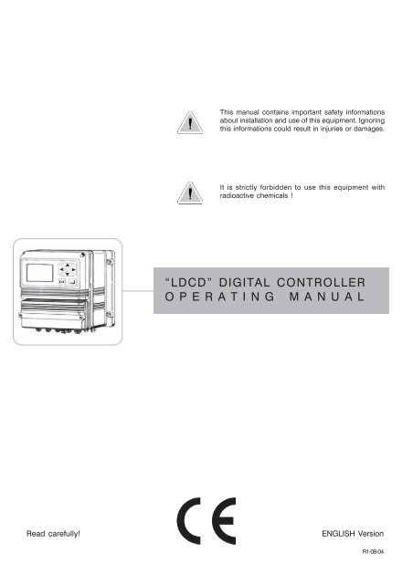
This <strong>manual</strong> contains important safety in<strong>for</strong>mationsabout installation and use of this equipment. Ignoringthis in<strong>for</strong>mations could result in injuries or damages.It is strictly <strong>for</strong>bidden to use this equipment withradioactive chemicals !“<strong>LDCD</strong>” DIGITAL CONTROLLEROPERATING MANUALRead carefully!ENGLISH VersionR1-08-04 1
“<strong>LDCD</strong>” series instruments comply with the following Europeanregulations:EN60335-1 : 1995, EN55014, EN50081-1/2, EN50082-1/2, EN6055-2,EN60555,3Based on directive CEE 73/23 c 93/68 (DBT Low voltage directive) anddirective 89/336/CEE (EMC Electromagnetic Compatibility)GENERAL SAFETY GUIDELINESDanger!In emergencies the instrument should be switched off immediately! Disconnect thepower cable from the power supply!When using instrument with aggressive chemicals observe the regulations concerningthe transport and storage of aggressive fluids!When installing outside European Community, always observe national regulations!Manufacturer is not liable <strong>for</strong> any unauthorized use or misuse of this product thatcan cause injury or damage to persons or materials!Caution!Instrument must be accessible at all times <strong>for</strong> both operating and servicing. Accessmust not be obstructed in any way!Feeder should be interlocked with a no-flow protection device.Instrument and accessories must be serviced and repaired by qualified andauthorised personnel only!Always read chemical safety datasheet!Always wear protective clothing when handling hazardous or unknown chemicals!2
IndexIndexIntroduction ................................................................................................................................................. 4Installation .................................................................................................................................................... 5“Function” Menu ......................................................................................................................................... 6“View Status” .............................................................................................................................................. 7“Setup” Menu ............................................................................................................................................. 8“1.Setpoint” ................................................................................................................................................ 9“2.Option” ................................................................................................................................................. 12“3.Clock” ................................................................................................................................................... 14“4.Print, Comm.” ...................................................................................................................................... 15“5.Password” ............................................................................................................................................ 17“PROBE” ................................................................................................................................................... 18“1.Calibrate” ............................................................................................................................................. 19“2.Self-Clean” ........................................................................................................................................... 20“3.Password” ............................................................................................................................................ 21“Probe Selection” ..................................................................................................................................... 22“Electrical wiring” ..................................................................................................................................... 24Technical features ..................................................................................................................................... 25Technical features ..................................................................................................................................... 26Controller’s Messages .............................................................................................................................. 273
IntroductionGENERAL DESCRIPTIONThe <strong>LDCD</strong> controller is a compact and user friendly wall mounted instrument to control and measureConductivity, providing reliable and accurate measurements. It features two ON/OFF set-point,two proportional set-points with digital outputs and a 0÷20 mA output proportional to the actualreading of the instrument that can be used <strong>for</strong> a chart recorder or remote control. The user interfaceis an intuitive keyboard and a baklit graphic display <strong>for</strong> a clear view even in dark environments. Thecontroller is cased in a IP65 plastic box, dimensions are 225x215x125mm.CONTROL PANELDisplayThe LCD displaygives an highresolution of thereading value andshows actualoperative status ofthe system.Date and timeKeyboardRangeESCEnterStatus of the controllerTemperatureSet-up menuProbeselectionUse keyboard (up, down, left and right) to make a selection or change set values.The “Enter” key confirms your choose, keep pressed “ESC” to cancel the selection andreturn to previous menu.Password 1 and 2 are independent and can be set separately.From main menu press “Up” key to show/hide temperature, date and probe value.From main menu press “Up” key to show/hide temperature, date and probe value.4
InstallationELECTRICAL WIRINGS:40 41 42 43 44 45F1F2F327 28 29 30 31 32 33 34 35 36 37J1J21 2 3 4 5 6 7 8 9 10 11 12 13 14 15 16 17 18 19 20 21 22 23 24 25 26F1: General protection fuse (6.3A)F2: Controller protection fuse (2A)F3: Alarm protection fuse (2A)1(Live) ; 2(Earth) ; 3(Neutral): Power Suppply (90÷240) VAC - 50/60Hz4(Live) ; 5(Earth) ; 6(Neutral): Output (90÷240) D1 - Setpoint17(Live) ; 8(Earth) ; 9(Neutral): Output (90÷240) D2 - Setpoint210(Live) ; 11(Earth) ; 12(Neutral): Output (90÷240) Probe cleaning13(N.O.) ; 14(common) ; 15(N.C.): Alarm output (Free of voltage contact)16(Ground) ; 17: Stand-By contact (STANDBY)18(Ground) ; 19: Level contact 120(Ground) ; 21: Level contact 222(Ground) ; 23(Signal Input) ; 24(Output +12V / Max20mA): Flow sensor*25(-) ; 26(+): RS485 Output27(-) ; 28(+): Output P1 proportional pump driven by pulses29(-) ; 30(+): Output P2 proportional pump driven by pulses31(-) ; 32(+): 4÷20mA output <strong>for</strong> Conductivity33(-) ; 33(+): 4÷20mA output <strong>for</strong> Temperature35(Ground) ; 36(Rx) ; 37(Tx): RS232 port- <strong>for</strong> PC/printer connection: 35 black - 36 green - 37 red- <strong>for</strong> modem connection: 35 black - 36 red - 37 green40(Ground/yellow/white); 41(Input Signal/green); 42(Power supply/brown): Temperature probe PT10043(Ground/blue) ; 44(Input Signal/red) ; 45(Input Signal/black): Conductivity probeJ1 - J2: see page 24*see page 245
“Function” Menufig.1In the main screen showed in fig.1 press “>” key to highlight “FUNCTION”. Press then “Enter” toconfirm selection. The controller will show the screen in fig.2. Press “ESC” at any time to get backin the normal operation screen (fig.1).fig.2You can choose in this menu to view the controller status, print the events log or activate theprobe cleaning procedure.123Highlight “View Status”and press “Enter” to getthe controller statusscreen, see page 7 <strong>for</strong>more in<strong>for</strong>mation.6Highlight “Print Status”and press “Enter”.Display shows “Sure?”.Press again “Enter” toconfirm printing* or press“ESC” to canceloperation.* It is needed a serialprinter connected on the“RS232” connector ofthe terminal block.Protocol 9600-8-N-1.Highlight “Probe Clean”and press “Enter”.Display shows “Sure?”.Press again “Enter” toconfirm probe cleaning**or press “ESC” to canceloperation** Use this <strong>manual</strong>cleaning function whenthe probe gives unsatisfyingresults(readen value is notstable).
“View Status”fig.3In the “View Status” screen in fig.3 there is a summary of the controller status, in particular thefollowing in<strong>for</strong>mation:D1 = Relay status <strong>for</strong> SetPoint 1. (Off ; On ).D2 = Relay status <strong>for</strong> SetPoint 2. (Off ; On ).P1 = Pump 1 proportional output.P2 = Pump 2 proportional output.(Off ; Shows pump stroke per minute when On).(Off ; Shows pump stroke per minute when On).A1 = Programmable Alarm 1. (Off ; On ).A2 = Programmable Alarm 2. (Off ; On ).L1 = Chemical tank 1 Level (Low ; High ).L2 = Chemical tank 2 Level (Low ; High ).Flow = Probe holder’s water flow (No if there’s no flow ; Yes ).Sby = StandbyDelay = Delay pump activation on start-upClean = Automatic probe cleaning(No, controller in normal operations; Yes, controllerin pause)(Off ; On)(Off ; On during clean status)Note: To disable all alarms press “ENTER”.7
“Setup” MenuIn the main screen showed in fig.1 press twice the “>” key to highlight “SETUP”. Press then“Enter” to confirm selection. The controller will show the screen in fig.4. Press “ESC” at any timeto get back in the normal operation screen (fig.1).fig.4This screen protects the access to the programming menu of the controller to avoid alteration ofset datas by unauthorized personnel. Default password is set to “0000”. Use arrow keys to enterpassword and then press “Enter” to confirm. See page 16 to know how to change password. Onceentered the correct password the display shows the screen in fig. 5.Use arrow keys to choose the desired function and press then “Enter” to confirm. Press “ESC” atany time to cancel operation.Highlight “1. Setpoint” and press “Enter” to confirm. The display will show the screen in fig. 6fig.5fig.6In this menu you can set the set-point’s outputs, the pump response and the alarm ranges.8
“1.Setpoint”Data in fig. 6 are the default values (Everything is OFF). Use arrow keys to highlight the desired valuein order to change it.“D1” is the digital output 1 of the controller.D1 Off < 100.0 µS :001.0“Off” means that the output is disabled. Must be switched to “On” to activate D1 output.“”.“100.0” is the setpoint value, it can be changed using arrow keys.“µS” is the range of the set-point, it can be switched to “mS”.“ :001.0” is the hysteresis value. It gives the working range of the relay, in our example above therelay switches on when the reading achieve 99,0 µS and it switches off when the reading goes over101,0 µS.“D2” is the digital output 2 of the controller.D2 Off < 100.0 µS :001.0“Off” means that the output is disabled. Must be switched to “On” to activate D1 output.“”.“100.0” is the setpoint value, it can be changed using arrow keys.“µS” is the range of the set-point, it can be switched to “mS”.“ :001.0” is the hysteresis value. It gives the working range of the relay, in our example above therelay switches on when the reading achieve 99,0 µS and it switches off when the reading goes over101,0 µS.9
“1.Setpoint”P1 Off 100.0 µS = 150 Pm200.0 µS = 000 Pm“P1” Is the digital proportional output 1 of the controller.“Off” means that this output is disabled. Must be switched to “On” to activate output P1.“100.0” is the setpoint value, it can be changed using arrow keys.“µS” is the range of the set-point, it can be switched to “mS”.“150 Pm” is the number of stroke per minute given to the pump <strong>for</strong> the corresponding value.“200.0” is the setpoint value, it can be changed using arrow keys.“µS” is the range of the set-point, it can be switched to “mS”.“000 Pm” is the number of stroke per minute given to the pump <strong>for</strong> the corresponding value.Referring to the above shown data as an example and the setpoint activated (“On”), the output will beactive and will drive the pump (if connected) at 150 strokes per minute when the readen value is loweror equal to 100 µS. The output will drive the pump in the range between100 and 200 µS proportionally(i.e: when reading is 150 µS the pump will be driven at 75 strokes per minute). When the reading is 200µS or higher the controller will keep the pump not working.10P2 Off 100.0 µS = 150 Pm200.0 µS = 000 Pm“P2” Is the digital proportional output 2 of the controller.“Off” means that this output is disabled. Must be switched to “On” to activate output P2.“100.0” is the setpoint value, it can be changed using arrow keys.“µS” is the range of the set-point, it can be switched to “mS”.“150 Pm” is the number of stroke per minute given to the pump <strong>for</strong> the corresponding value.“200.0” is the setpoint value, it can be changed using arrow keys.“µS” is the range of the set-point, it can be switched to “mS”.“000 Pm” is the number of stroke per minute given to the pump <strong>for</strong> the corresponding value.Referring to the above shown data as an example and the setpoint activated (“On”), the output will beactive and will drive the pump (if connected) at 150 strokes per minute when the readen value is loweror equal to 100 µS. The output will drive the pump in the range between100 and 200 µS proportionally(i.e: when reading is 150 µS the pump will be driven at 75 strokes per minute). When the reading is 200µS or higher the controller will keep the pump not working.
“1.Setpoint”A1 Off < 080.0 µS d:00 m“A1” is the programmable alarm1 that activates the alarm output.“Off” means that this output is disabled. Must be switched to “On” to activate output.““in order to activate the output when the reading value is higher than indicated.“08.0” is the alarm value, it can be changed using arrow keys.“µS” is the range of the alarm, it can be switched to “mS”.“d:00 m” is the output activation delay, the readen value must be lower (or higher) than thespecified alarm value <strong>for</strong> this time to have the alarm output active, can be set between 0 and 99minutes.A2 Off > 220.0 µS d:00 m“A2” is the programmable alarm2 that activates the alarm output.“Off” means that this output is disabled. Must be switched to “On” to activate output.“>“ activates the output when the reading value is higher than indicated. It can be switched to “
“2.Option”fig.5Use arrow keys to choose the desired function and press then “Enter” to confirm. Press “ESC” at anytime to cancel operation.Highlight “2. Option” and press “Enter” to confirm. The display will show the screen in fig. 7.fig.7T (Tau): it’s a factor that determines how quickly the reading on the display follows the reading of theprobe. It’s set by default to 5 and it can be changed between 0 and 30. The more close to 0 this value isset and the more quickly the reading on the display will change, take in consideration that quicklychanges on the display will result in unstable readings.Temp. comp.: it’s the temperature compensation factor. It can be changed in the range between (0.0%and 5.0%), should be set according the chemical properties of the measured media. When the temperatureis out of range the controller displays the reading value blinking and the temperature compensation isnot per<strong>for</strong>med.Output delay: it’s the pump output activation delay. Can be chosen between 0 and 99 minutes and ittakes effect on start up of the controller, quitting from stand-by condition and after a “Flow Alarm”.Flow stop: choose to stop the pumps when the “No Flow” is on (no flow in the probe holder) if it is set“Yes” the pumps connected to the controller will be stopped. If it is set “No” the signal will not affect theoperations of the pumps.Level stop: choose to stop the pumps when the “Level alarm” is on (no chemical in the drum) if it is set“Yes” the pumps connected to the controller will be stopped. If it is set “No” the signal will not affect theoperations of the pumps.12
“2.Option”Flow: choose the flow sensor input, set to “Normal” activates the standard flow sensor (“SEPR” proxysensor). Set to “Reverse” the digital logic of the sensor is inverted. Set to “Disable” the flow sensor is notenabled. See pag. 23.Flow “Normal” Flow “Reverse”Flow “Disable”Output current: changes the output current range, can be set to 0/20mA or 4/20mA.“m” and “M”: defines the output current range according to the reading of the controller.Basically the controller will give a current output of 0 or 4 mA when the µS value readen will be equal to“m”. The controller will give a current output of 20 mA when the µS value readen will be equal to “M”.Between the range defined by “m” and “M” the controller gives a current output proportional.T.MAX DOS.: maximum time dosing alarm. This alarm prevents the pump to dose if a set time isreached. To activate the alarm move the cursor on “01M” and set the time (from 0 to 99 minutes). Tosetup the alarm move the cursor on “DOSING”. Use “UP” or “DOWN” keys to change this voice. On“STOP” mode the pump will stop the dosing procedure once the set time is reached. The pump’sdisplay will show the alarm condition and requires to press a key to continue while into “View Status”menu. On “DOSING” mode the pump will NOT stop the dosing procedure once the set time is reached.Instrument will show the alarm condition only.13
“3.Clock”fig.5Use arrow keys to choose the desired function and press then “Enter” to confirm. Press “ESC” at anytime to cancel operation.Highlight “3. Clock” and press “Enter” to confirm. The display will show the screen in fig. 8.fig.8Use arrow keys to set date and time in the following <strong>for</strong>mat:Week day DD/MM/YYHH.MM.SS. (24h)Press “Enter” to confirm. The controller will ask a confirmation like in fig. 9:fig.9Press “Enter” to save entered datas and return to menu in fig.5.14
“4.Print, Comm.”fig.5Use arrow keys to choose the desired function and press then “Enter” to confirm. Press “ESC” at anytime to cancel operation. Highlight “4. Print., Comm.” and press “Enter” to confirm. The display willshow the screen in fig. 16.fig.16“Inst. ID”: is the controller identity number. It’s needed to change it only when the controller isconnected to a network that has more than one controller.“Tx at 00.00 ev. 00.00”: set the sending of the status at a selectionable time (AT) each hour/minuteset. Use arrow keys to change time and interval.“or if: Off”:disable printing when set to “Off”.enable printing also whenever a generic alarm occurs when set to“alarm”.enable printing also whenever there’s no flow in the probe holderwhen set to “flow”.enable printing also whenever an alarm occurs and when there’s noflow in the probe holder when set to “alarm,flow”.enable printing also whenever there’s no chemical in the drum whenset to “level”.enable printing also whenever an alarm occurs and when there’s nochemical in the drum when set to “alarm, level”.enable printing also whenever there’s no flow in the probe holder andwhen there’s no chemical in the drum when set to “flow, level”.enable printing also whenever an alarm occurs, when there’s no flowin the probe holder and when there’s no chemical in the drum if set to“alarm, flow, level”.15
“4.Print, Comm.”fig.16“Modem”: no “SMS”: no“Modem”: yes “SMS”: no“Modem”: yes “SMS”: yesPrinter, PC or LDCOMM setting.PSTN (es.: 56K/V90) setting. The instrument can be remotecontrolled: setting and status.GSM modem setting. The instrument sends short messages (SMS)during alarm conditions or at selected interval (see “TX AT” functionon page 15). The instrument can send short messages to amaximum of 9 phone numbers saved on the SIM CARD.Press “Enter” at the end. The instrument will display “SAVE?”. Press “Enter” to confirm.Press “Enter” to save the settings and go back to the menu (fig.5).16
“5.Password”fig.5Use arrow keys to choose the desired function and press then “Enter” to confirm. Press “ESC” at anytime to cancel operation.Highlight “5. Password” and press “Enter” to confirm. The display will show the screen in fig. 9.fig.10This password protects the “Setup” menu from unauthorized personnel, use arrow keys to set thenew password between 0000 and 9999 then press “Enter” to save. Forgotten password can not beretrieved, in this case a reset of the controller is needed. To reset the controller shut downpower supply and power on again and press “ESC” when the screen in fig.11 shows on thedisplay . Wait re-set screen and then press “Enter” to confirm the reset.fig.1117
“PROBE”fig.1In the main screen showed in fig.1 press “>” key to highlight “PROBE”. Press then “Enter” to confirmselection. The controller will show the screen in fig.12. Press “ESC” at any time to get back in thenormal operation screen (fig.1).fig.12This screen protects the access to the programming menu of the controller to avoid alteration of setdata by unauthorized personnel. Default password is set to “0000”. Use arrow keys to enter passwordand then press “Enter” to confirm. See page 20 to know how to change password. Once entered thecorrect password the display shows the screen in fig. 13.fig.13Calibrate: access this menu to calibrate the probe.Self-Clean: access this menu to set automatic probe clean procedure.Password: access this menu to change the password of the “PROBE” menu. Please note this is nothe same password used to protect the “SETUP” menu.18
“1.Calibrate”“1.Calibrate” is the probe setting menu, once entered you have the display shows the screen in fig.14.To make the probe setting is needed a buffer solution that has a value close to the working conditionsin order to per<strong>for</strong>m the calibration.ABCfig.14The screen is divided in three areas. The first one indicated as area “A” in the picture above shows theactual reading of the conductivity and temperature, it also shows the last calibration date. Those dataare not editable.area “B” shows conductivity probe parameters. Editable data are:“K”: probe factor. See “Probe Selection” paragraph to have more in<strong>for</strong>mation how to change thisparameter.“Temp”: buffer solution temperature. Measure the buffer solution temperature and enter data in thisfield.“P1”: set “zero”. Remove the probe from the probe holder and wipe it gently. Use arrow keys to movethe cursor in “Set-P1”, read the actual value in the “A” area and wait until it is stabilized. During thecalibration process, the value in the “A” area could be different from the buffer solution value. Wait astable reading. Press “Enter”. “OK” will appear next to “P1: 0.000mS”.Use the arrow keys to move the cursor on “SAVE” and press “Enter” to confirm in order to saveentered data. If the calibration of “P2” is also needed use the arrow keys to move cursor in this field.“P2”: probe calibration with a buffer solution. Dip the probe in the buffer solution and use the arrow keysto move the cursor on “P2”, enter the buffer solution range (“mS” o “µS”) by moving the prompt over“µS” and changing it using the keyboard. Then move cursor on solution value and enter the buffersolution value. Use arrow keys to move the cursor in “Set-P2”, read the actual value in the “A” area andwait until it is stabilized. Press “Enter”. “OK” will appear next to “P2: 1.413 mS”.Use the arrow keys to move the cursor on “SAVE” and press “Enter” to confirm in order to saveentered data.area “C” shows the temperature probe configuration parameters. The controller is already set when isdelivered and usually it is not needed to make this configuration. To calibrate the temperature use thearrow keys to move cursor on the temperature and enter measured value. Use arrow keys to move thecursor in “Set-T” and press “Enter”. A blinking “!” followed by one number “1” will appear below “Set-T”.Pressing again the “Enter” key number will be increased by one unit to confirm the data acquisition.19
“2.Self-Clean”In the menu in fig.13 highlight “Self-Clean” and press “Enter”.fig.13The display will show the screen in fig.15.fig.15This screen shows:“Cycle”: the time between each cleaning. Can be set between 0 (disabled) and 999 minutes.“Clean Time”: probe cleaning time. Can be set between 0 (disabled) and 999 seconds.“Restore Time”: is the probe recovery time needed to come back in full operations after thecleaning. Can be set between 0 (disabled) and 999 minutes.“Clean on alarm”: automatic probe cleaning when the alarm on the setpoints is active. The probewill not read till the end of the cleaningNote: During “Clean Time”, “Restore Time” and “Clean on alarm” the controller’s outputs areDISABLED.20
“3.Password”fig.5Use arrow keys to choose the desired function and press then “Enter” to confirm. Press “ESC” at anytime to cancel operation.Highlight “3. Password” and press “Enter” to confirm. The display will show the screen in fig. 10.fig.10This password protects the “PROBE” menu from unauthorized personnel, use arrow keys to set thenew password between 0000 and 9999 then press “Enter” to save. Forgotten password can not beretrieved, in this case a reset of the controller is needed. To reset the controller shut downpower supply and power on again and press “ESC” when the screen in fig.11 shows on thedisplay . Wait re-set screen and then press “Enter” to confirm the reset.fig.1121
“Probe Selection”The probe should be selected taking in consideration the working range, plant installation andchemical compatibility. Please find here below a table that shows the most appropriate probe <strong>for</strong> aselection of plant installation and ranges.Conductivity 0.1µS 1µS10µS 100µS 1mS 10mS 100mS 1000mSohm/cm -1 10M 1M 100K 10K 1K 100 10 1ResistivityDistilled WaterDrinking waterCooling towerSea water / SalamoiaAcids/Concentrated BasesProbe factor K=10Probe factor K=1Probe factor K=0,1See table in pag.22 <strong>for</strong> more details about probes.22
“Probe Selection”Functions ECDI/1 ECDIM/1 ECDI/02 ECDIM/02 ECDICPT/1 ECDICMPT/1 ECDICPT/02 ECDICMPT/02 ECDC ECDCCPTECDHTP/1/PT100ECDHTP/01/PT100Measurement Range 0÷5 mS 0÷5 mS 0÷200 µS 0÷200 µS 0÷5 mS 0÷5 mS 0÷200 µS 0÷200 µS 0÷20 mS 0÷20 mS 0÷2 mS 0÷2 mSK Factor 1 1 0,2 0,2 1 1 0,2 0,2 0,8 0,8 1 0,1MaxPressure/Temperature7bar / 60 °C0bar / 90 °C7bar / 60 °C0bar / 90 °C7bar / 60 °C0bar / 90 °C7bar / 60 °C0bar / 90 °C7bar / 60 °C0bar / 90 °C7bar / 60 °C0bar / 90 °C7bar / 60 °C0bar / 90 °C7bar / 60 °C0bar / 90 °C7bar / 60 °C0bar / 90 °C7bar / 60 °C0bar / 90 °C15bar / 200 °C 15bar / 200 °CBody PVCC PVCC PVCC PVCC PVCC PVCC PVCC PVCC PVCC PVCC SS SSElectrodes SS SS SS SS SS SS SS SS Graphite Graphite SS SSDiameter 3/4" 1/2" 3/4" 1/2" 3/4" 1/2" 3/4" 1/2" 3/4" 3/4" 3/4" 3/4"Probe Length 48 mm 48 mm 64 mm 64 mm 48 mm 48 mm 64 mm 64 mm 69 mm 69 mm 74 mm 74 mmElectrical Connection 3 wires 3 wires 3 wires 3 wires 5 wires 5 wires 5 wires 5 wires 3 wires 5 wires 5 wires 5 wiresConnector andCable LengthAutomatic TemperatureCompensation4 Poles connector and 4 m cable lengthNO NO NO NO PT 100 PT 100 PT 100 PT 100 NO PT 100 PT 100 PT 100Functions ECDHL/01 ECDHL/1 ECDHL/10 ECDHLC-PT100/01 ECDHLC-PT100/1 ECDHLC-PT100/10Measurement Range 0÷200 µS 0,2÷20 mS 20÷200 mS 0÷200 µS 0,2÷20 mS 20÷200 mSK Factor 0,1 1 10 0,1 1 10MaxPressure/Temperature7bar / 70 °C 7bar / 70 °C 7bar / 70 °C 7bar / 70 °C 7bar / 70 °C 7bar / 70 °CBody Epoxy Epoxy Epoxy Epoxy Epoxy EpoxyElectrodes Platinum Platinum Platinum Platinum Platinum PlatinumDiameter 12 mm 12 mm 12 mm 12 mm 12 mm 12 mmProbe Length 170 mm 170 mm 170 mm 170 mm 170 mm 170 mmElectrical Connection 3 wires 3 wires 3 wires 5 wires 5 wires 5 wiresConnector andCable LengthAutomatic TemperatureCompensation9 m 9 m 9 m 9 m 9 m 9 mNO NO NO PT 100 PT 100 PT 10023
“Electrical wiring”“Flow Sensor”A proxy sensor model “SEPR” can be used to sense the flow inside the probe holder, make wirings as follows: bluewire to terminal n.22 ; black wire to terminal n.23 ; brown wire to terminal n.24 and set “Flow” to “normal” in menu“Option”. A flow sensor with free of voltage contact Normally Closed when there is flow, make wirings on terminalsn.23 and n.24 and set “Flow” to “normal” in menu “Option”. A flow sensor with free of voltage contact NormallyOpen when there is flow, make wirings on terminals n.23 and n.24 and set “Flow” to “reverse” in menu “Option”.“Temperature Probe”“<strong>LDCD</strong>” controller is designed to work with temperature probes type “PT100” (platinum sensor, 100Ohm at 0°C). Toreduce the reading error typical connection of this sensor is made of four wires, the controller anyway accepts threewire connections too. Make wirings as follows: ground (yellow and white wires) to terminal n.40, signal (gree wire) toterminal n.41, power supply (brown wire) to terminal n.42. Using the temperature probe built inside the “ECDCCPT” probeconnect white and yellow wires to terminal n.40 ; green wire to terminal n.41 ; brown wire to terminal n.42.“Conductivity probe”According to the used probe make the following wirings: shield to terminal n.43, probe wires to terminals n.44 andn.45. Using the “ECDCCPT” probe make the following wirings: blue wire (cable shield) to terminal n.43, red wire toterminal n.44, black wire to terminal n.45.“Printer Port”Use a shielded cable not longer than 50 meters to connect a printer to the controller, wire the shield to terminal n.35and the signal wire to terminal n.37 (Data Transmission). Set-up printer as follows: Communication speed: 9600baud,control bit: 8, parity: none and 1 bit stop.“Communication Ports”The instrument has two communication ports built in (RS232 - RS485). User may select a port using J1 and J2configuration jumpers. Use RS232 port <strong>for</strong> a local printer or PC connection (Rx-Tx 9600-8-N-1). Use RS485 port <strong>for</strong> remotecontrol.1231-2 Closed: RS232 On2-3 Closed: RS485 OnJ1121-2 Closed: Termination resistance <strong>for</strong>RS48524J2
Technical featuresFunctions<strong>LDCD</strong>DisplayControlsCalibrationEnvironment WorkingTemperatureSet PointsControl InputsLCD Backlight Graphic DisplayDigital KeyboardManual0°C a 50°C - 0% a 95% (non condensing) relativehumidityTwo On/Off set points, two digital proportionalChemical tank level control, stand-by*Input Impedance - -Relay Output (On-Off)AlarmDelay**Max Resistive LoadPower SupplyPower ConsumptionFuseBack up DataGalvanic IsolationCasing MaterialMountingDimensionsNet WeightSerial port <strong>for</strong> printerTemperatureCompensationProbe Cleaning OutputProbe SElection2 Voltage outputVoltage Free Contact Relay (Fuse Protected)Programmable "Power-on" Delay5A - 220 VACUniversale 90÷240 VAC ; 50/60 HzAverage 10WOutput, instrument and alarm fuse protecionsYESYESABS - IP65 boxWall225 x 215 x 110 mm1,2 kgRS232Automatic0 ÷ 100 °CYESYES25
Technical featuresPROBE RANGE RESOLUTIONK = 0,1 0 ÷ 300,0 µS 0,1 µSK = 0,1 0 ÷ 3,000 mS 1 µSK = 1 0 ÷ 3,000 mS 1 µSK = 1 0 ÷ 30,00 mS 10 µSK = 10 0 ÷ 30,00 mS 10 µSK = 10 0 ÷ 300,0 mS 100 µS26
Controller’s Messages“HIGH WARNING”This message pop-up on the display when the readen value is above the meter’s range. (See technicalfeatures table in page 24).“LOW WARNING”This message pop-up on the display when the readen value is below the meter’s range. (See technicalfeatures table in page 24).“WARNING”This message pop-up on the display when the status of the controller is in alarm, it can be caused by:no flow in the probe holder, set-point alarm, no chemical in the drum. Alarm is specified in the menu“Function” -> “View Status” (pag.6).27
28When dismantling an instrument please separate material types and send them according to local recycling disposalrequirements. We appreciate your ef<strong>for</strong>ts in supporting your local Recycle Environmental Program.Working together we’ll <strong>for</strong>m an active union to assure the world’s invaluable resources are conserved.