

SS41 Series Low Gauss Bipolar Hall Effect Position Sensors
SS41 Series Low Gauss Bipolar Hall Effect Position Sensors
SS41 Series Low Gauss Bipolar Hall Effect Position Sensors

You also want an ePaper? Increase the reach of your titles
YUMPU automatically turns print PDFs into web optimized ePapers that Google loves.
Installation Instructions for the ISSUE 2<br />
<strong>SS41</strong> <strong>Series</strong> <strong>Low</strong> <strong>Gauss</strong> <strong>Bipolar</strong> <strong>Hall</strong> <strong>Effect</strong><br />
<strong>Position</strong> <strong>Sensors</strong><br />
ELECTRICAL CHARACTERISTICS<br />
Catalog Listing <strong>SS41</strong>/<strong>SS41</strong>D Min. Typ. Max. Remarks<br />
Supply Voltage 4.5 24 VDC<br />
Supply Current<br />
4 mA<br />
6 mA<br />
8.7 mA<br />
15 mA<br />
Vs = 4.5 VDC<br />
Vs = 6 to 24 VDC<br />
Output Voltage (Operated)<br />
0.15 V<br />
0.15 V<br />
0.40 V<br />
0.45 V<br />
10 mA<br />
-40 to +125°C<br />
+125 to +150°C<br />
Output Current (Operated)<br />
Output Leakage Current (Released) 10 µA Leakage into sensor output<br />
Output Switching Time<br />
Rise<br />
Fall<br />
0.2 µs<br />
0.5 µs<br />
1.5 µs<br />
1.0 µs<br />
10 to 90%<br />
90 to 10%<br />
PK 88781<br />
MAGNETIC CHARACTERISTICS<br />
Temperature<br />
Range<br />
Max.<br />
Op.<br />
<strong>Gauss</strong><br />
Min.<br />
Rel.<br />
Min.<br />
Dif.<br />
0 to 85°C 150 -150 50<br />
-40 to 125°C 200 -200 40<br />
-55 to 150°C 250 -250 30<br />
25°C Typical 40 -40 80<br />
SOLDERING/ASSEMBLY INSTRUCTIONS<br />
Leads must be adequately supported during any<br />
forming or shearing operation to ensure that the<br />
leads are not stressed inside the plastic case.<br />
Recommended PC board wave soldering<br />
temperature is 250 to 260°C (482 to 500°F), with a<br />
duration of 3 seconds maximum.<br />
CATALOG LISTING<br />
Catalog Output<br />
Listing<br />
<strong>SS41</strong> Digital current sinking<br />
Reverse polarity protection<br />
is standard<br />
Magnetic<br />
Type<br />
<strong>Bipolar</strong><br />
ABSOLUTE MAXIMUM RATINGS<br />
Supply Voltage (Vs)<br />
Voltage externally<br />
applied to output<br />
Output Current<br />
Temperature Range<br />
Magnetic Flux<br />
-24 to +28 VDC<br />
+28 VDC max, OFF condition<br />
only<br />
-0.5 V min., OFF or ON condition<br />
20 mA<br />
-55 to +170°C (-67 to +338°F)<br />
No limit. Circuit cannot be<br />
damaged by magnetic overdrive<br />
Absolute maximum ratings are the extreme limits<br />
that the device will withstand without damage to the<br />
device. However, the electrical and mechanical<br />
characteristics are not guaranteed as the maximum<br />
limits (above recommended operating conditions)<br />
are approached, nor will the device necessarily<br />
operate at absolute maximum ratings.<br />
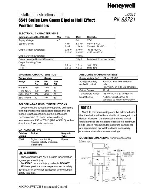
MOUNTING DIMENSIONS (for reference only)<br />
These products are NOT suitable for protection<br />
against personal injury.<br />
To AVOID personal injury or death, DO NOT<br />
USE these products as emergency stop or safety<br />
devices, or in any other application where human<br />
safety is at risk.<br />
MICRO SWITCH Sensing and Control
<strong>SS41</strong> <strong>Series</strong> Issue 2 PK 88781<br />
INTERFACING DIAGRAMS<br />
WARRANTY/REMEDY<br />
Honeywell warrants goods of its manufacture as<br />
being free of defective materials and faulty<br />
workmanship. Contact your local sales office for<br />
warranty information. If warranted goods are<br />
returned to Honeywell during the period of<br />
coverage, Honeywell will repair or replace without<br />
charge those items it finds defective. The foregoing<br />
is Buyer’s sole remedy and is in lieu of all other<br />
warranties, expressed or implied, including<br />
those of merchantability and fitness for a<br />
particular purpose.<br />
For application assistance, current specifications,<br />
pricing or name of the nearest Authorized<br />
Distributor, contact a nearby sales office. Or call:<br />
Specifications may change without notice. The<br />
information we supply is believed to be accurate<br />
and reliable as of this printing. However, we<br />
assume no responsibility for its use.<br />
While we provide application assistance,<br />
personally and through our literature, it is up to the<br />
customer to determine the suitability of the product<br />
in the application.<br />
1-800-537-6945 USA<br />
1-800-737-3360 Canada<br />
1-815-235-6847 International<br />
FAX<br />
1-815-235-6545 USA<br />
INTERNET<br />
http://www.sensing.honeywell.com<br />
info@micro.honeywell.com<br />
MICRO SWITCH<br />
Honeywell Inc.<br />
11 West Spring Street<br />
Freeport, Illinois 61032<br />
Printed with Soy Ink<br />
on 50% Recycled Paper<br />
PK 88781-2-EN IL50 GLO 897 Printed in USA<br />
Helping You Control Your World


