Lab #7: Analog I/O and Closed Loop Programming - WVU ...
Lab #7: Analog I/O and Closed Loop Programming - WVU ...
Lab #7: Analog I/O and Closed Loop Programming - WVU ...

Create successful ePaper yourself
Turn your PDF publications into a flip-book with our unique Google optimized e-Paper software.
<strong>Lab</strong> <strong>#7</strong>: <strong>Analog</strong> I/O <strong>and</strong> <strong>Closed</strong> <strong>Loop</strong><br />
<strong>Programming</strong><br />
Objectives:<br />
• Introduction to analog output<br />
• Familiarization with basic output <strong>and</strong> functions<br />
• Familiarization with scaling<br />
• Introduction to closed loop control with analog sensors<br />
Introduction:<br />
During the course of mechanical engineering, an engineer may have a need to be<br />
able to turn a motor or other apparatus at a variable speed by feeding it specific voltages.<br />
An engineer may also have a need for a program the runs continuously to monitor or<br />
record an input, or continuously change an output with respect to this input. These tasks<br />
often require the use of analog inputs <strong>and</strong> outputs.<br />
<strong>Analog</strong> Input<br />
<strong>Analog</strong> input reads the state of an analog apparatus. Unlike digital input, however,<br />
analog input can give us more specific information. An analog input returns a number<br />
related to the voltage present on its input terminals. The voltage usually comes from a<br />
sensor <strong>and</strong> is proportional to a measured quantity like pressure, temperature, speed, etc.<br />
Alternately, the input can represent the desired temperature, pressure, etc. <strong>and</strong> in these<br />
cases usually comes from a variable resistor called a potentiometer. The volume control<br />
knob on your stereo is usually connected to a potentiometer.<br />
Either way, the voltage represents an actual or desired level of something. The<br />
voltage must be scaled to properly represent engineering units. Scaling is a simple<br />
mathematical function—usually linear—more on that later. The analog voltage is<br />
converted to a number by the <strong>Analog</strong> to Digital Converter (ADC or A/D Converter).<br />
These will be discussed in detail in class. In your interface boards, the range can be<br />
selected by software, but the system is set up to provide an input range of -10V - +10V as<br />
the default. Your converters have 12 bits of resolution so what you read from the analog<br />
input channels will be accurate to +/-0.00488 V.<br />
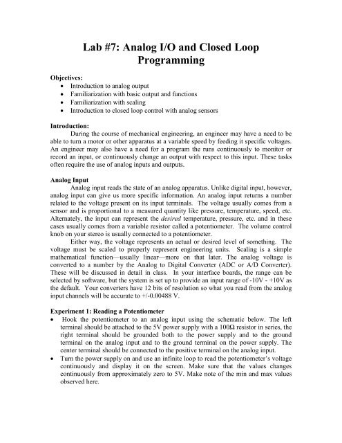
Experiment 1: Reading a Potentiometer<br />
• Hook the potentiometer to an analog input using the schematic below. The left<br />
terminal should be attached to the 5V power supply with a 100Ω resistor in series, the<br />
right terminal should be grounded both to the power supply <strong>and</strong> to the ground<br />
terminal on the analog input <strong>and</strong> to the ground terminal on the power supply. The<br />
center terminal should be connected to the positive terminal on the analog input.<br />
• Turn the power supply on <strong>and</strong> use an infinite loop to read the potentiometer’s voltage<br />
continuously <strong>and</strong> display it on the screen. Make sure that the values changes<br />
continuously from approximately zero to 5V. Make note of the min <strong>and</strong> max values<br />
observed here.
Fig. 6-3—Potentiometer diagram<br />
Fig. 5-2—<strong>Analog</strong> inputs<br />
<strong>Analog</strong> output<br />
<strong>Analog</strong> output is similar to the digital output that has already been covered,<br />
however, instead of just being on or off, you may output a variable voltage. The DAQ<br />
Board is capable of outputting a voltage between positive 10V <strong>and</strong> negative 10V;<br />
however this experiment will only use ±5V. If this output is hooked to a motor, as it is<br />
here, it means that the speed of the motor can be controlled by changing the output<br />
voltage.<br />
The chip attached to the DAQ Board’s analog output pins <strong>and</strong> shown in the figure<br />
serves an important purpose. Although the DAQ board can output a variable voltage, it is<br />
only capable of supplying 5mA of current. Such a small current is insufficient to turn a<br />
motor or other device. For this reason, the motor control chip is present. Using an<br />
operational amplifier, it is possible to magnify the current using an external source, while<br />
keeping the voltage output by the DAQ board the same. This allows the user to run a<br />
small motor at variable speeds directly from the DAQ.
Fig. 6-1—Motor control chip<br />
Using the DAQ board’s analog output function<br />
The analog_out function in the mechlab toolbox requires two parameters, channel<br />
<strong>and</strong> voltage. The DAQ board has two analog output channels, <strong>and</strong> can accept voltages<br />
ranging from -10V to +10V, <strong>and</strong> is accurate to approximately 0.001V. This give much<br />
flexibility to specify exactly what the user needs.<br />
Aside from the analog_out function, a secondary function called motor_out has<br />
been written. The purpose of this function is to easily scale -5V to +5V to -100% to<br />
+100%. The reason for this is that this is a simpler way to comm<strong>and</strong> the motor when<br />
using an encoder, as Matlab’s reaction time is too slow to accurately read the encoder if it<br />
is running much faster than 5V. It is important to underst<strong>and</strong> that these comm<strong>and</strong>s are<br />
essentially the same, however, it is encouraged that you make use of the motor_out<br />
comm<strong>and</strong> as often as possible for simplicity <strong>and</strong> avoidance of erroneous encoder<br />
readings. The motor_out comm<strong>and</strong>, like the analog_out, requires two parameters: channel<br />
(1 or 2) <strong>and</strong> speed (-100 to +100).<br />
Scaling<br />
Many sensors do not begin reading at 0 units of what they are measuring. For<br />
instance, the temperature sensors you will use in this lab will output a voltage of<br />
0.01V/°F. However, the sensor has a base temperature reading of 70°F, meaning if you<br />
would get a reading of 0.01°F, the temperature is 71°F rather than 1°F. For this reason,<br />
the sensor reading must be scaled using the line equation from basic Algebra:<br />
y=mx+b (1)<br />
Using this equation, the programmer can write a function to directly display the<br />
meaning of the output, rather than a voltage that still needs to be interpreted.<br />
<strong>Closed</strong> loop programming<br />
A closed loop program is one that executes indefinitely until manually stopped. In<br />
this lab, you will build a thermostat <strong>and</strong> a variable speed motor. Using the thermostat as
an example, think of how a heating system works. A desired temperature is given, which<br />
is compared to the room temperature. If the room temperature is lower than the desired<br />
temperature, the heat turns on, but if it is higher, the heat stays off. A person would not<br />
want to manually turn the heat on or off constantly to keep the room at the desired<br />
temperature, nor would the person want to have to continuously tell the thermostat to<br />
check the temperature. In essence, this is closed loop control. An infinite loop is created,<br />
so that the program will run on its own, over <strong>and</strong> over, without any external intervention,<br />
aside from changing the desired setpoint. “Set it <strong>and</strong> forget it,” as they say.<br />
Experiments:<br />
Experiment 1: Using analog speed control<br />
Connect the motor to one of the motor outputs <strong>and</strong> turn it on using the syntax<br />
motor_out(ch,speed). Change the speed several times <strong>and</strong> notice how the motor speed<br />
changes.<br />
Fig. 6-2—Motor connected to analog output<br />
Experiment 2: Variable speed control<br />
• Using the potentiometer as a setpoint, write a program to continuously vary the speed<br />
of the motor with respect to the position of the potentiometer. The motor should spin<br />
in reverse from -100 to 0 while the potentiometer is between 0 <strong>and</strong> 2V. The motor<br />
should remain off while the potentiometer reads between 2V <strong>and</strong> 3V. The motor<br />
should spin forward from 0 to +100 while the potentiometer reads between 3V <strong>and</strong><br />
5V. You will need to using scaling for this part.<br />
Project: Thermostat
• Attach the temperature sensor to the analog input. Scale its output to print the<br />
temperature in degrees. (See previous information on how this sensor reads.)<br />
• Scale your potentiometer’s reading of 0 to 5V to be 70°F to 140°F<br />
• Connect a 100Ω resistor directly to the digital output, so that when turned on it will<br />
heat up. CAUTION: THIS GETS HOT! Do not leave this on long or the resistor will<br />
burn.<br />
• Using the temperature sensor to detect the temperature of the resistor, write a program<br />
so that the potentiometer can be used to give a setpoint, this setpoint will be compared<br />
to the temperature of the resistor, <strong>and</strong> the resistor will turned on or off according to<br />
the temperature of the resistor compared to the setpoint temperature. Demonstrate this<br />
program to a TA.<br />
Fig. 6-5—Thermostat
Questions:<br />
1. (5 pts) Describe how the analog_out <strong>and</strong> the motor_out are related, <strong>and</strong> explain<br />
how the motor_out works, in relation to the analog_out comm<strong>and</strong>.<br />
2. (5 pts) Show the calculations needed to scale the motor input versus the<br />
potentiometer output in the closed loop motor control.<br />
3. (5 pts) Tell why the input is not simply scaled, but a “space” called a deadb<strong>and</strong><br />
is left in the center of the potentiometer input.<br />
4. (10 pts) Include your commented <strong>and</strong> formatted code for the closed loop motor<br />
speed control program.<br />
5. (Project)<br />
a. (15 pts) Include the code for temperature control project.<br />
b. (10 pts) Show the calculations for scaling the temperature input.