Lab 4: Using the Digital Multimeter (DMM)
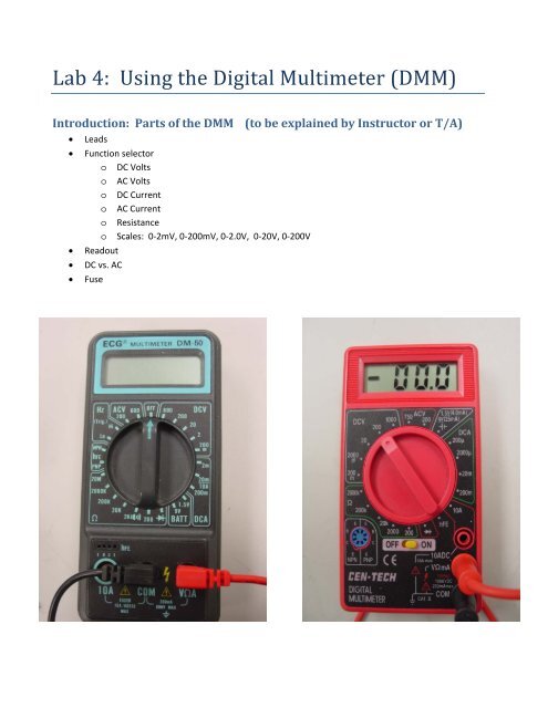
Lab 4: Using the Digital Multimeter (DMM)
Lab 4: Using the Digital Multimeter (DMM)

You also want an ePaper? Increase the reach of your titles
YUMPU automatically turns print PDFs into web optimized ePapers that Google loves.
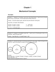
Resistor Color CodesResistor values can be determined by “reading” <strong>the</strong> bands of color printed on <strong>the</strong> resistor.Resistors of different wattages showing color code bands. Bottom = 0.25W. Color bands give resistanceand tolerance. Gold tolerance band is +/‐ 5%, silver is +/‐ 10%. Read values by taking first two digits andmultiply by 10 d3 where d3 is <strong>the</strong> number represented by <strong>the</strong> third color band. Chart is below. For example<strong>the</strong> resistor in <strong>the</strong> middle is a 1W, 47 x 10 3 Ω or 47kΩ resistor. The one above it is 2W, 27 x 10 2 Ω or 2700Ωor 2.7kΩ.
Experiment 1: Resistor tolerances and <strong>DMM</strong> accuracyEquipment:<strong>DMM</strong>, five x 1kΩ resistors.Procedure:• <strong>Lab</strong>el resistors with your lab station number and a letter, a,b,c, d or e• <strong>Lab</strong> partner 1 measure <strong>the</strong> resistance of each resistor and record• <strong>Lab</strong> partner 2 measure <strong>the</strong> resistance of each resistor and record• Repeat, so that each person measures each resistor three times.• Trade multimeters with one of <strong>the</strong> o<strong>the</strong>r groups at your bench and repeat, noting <strong>the</strong> new <strong>DMM</strong> inyour records. Compare <strong>the</strong> results by analyzing <strong>the</strong> differences between <strong>the</strong> measurements to seeif you can detect <strong>the</strong> influence of <strong>the</strong> <strong>DMM</strong>, <strong>the</strong> influence of <strong>the</strong> operator, and <strong>the</strong> tolerance of <strong>the</strong>resistors.Writeup:Write up this experiment as instructed in <strong>the</strong> <strong>Lab</strong> Report Guide, posted on eCampus under <strong>the</strong> “<strong>Lab</strong>s”folder. Pay special attention to <strong>the</strong> analysis section.Experiment 2: LED Current and output intensityEquipment:<strong>DMM</strong>, LED, 4 x 1kΩ resistor, breadboard, power supply, wiresProcedure:• Construct a circuit as shown in Figure 1. The LED has two leads and a flat spot on one side of <strong>the</strong>case. The Anode is usually <strong>the</strong> longer of <strong>the</strong> two leads, and <strong>the</strong> cathode has <strong>the</strong> flat spot. TheAnode goes toward <strong>the</strong> “+” side of <strong>the</strong> circuit and <strong>the</strong> cathode toward <strong>the</strong> “–“ side. Measure <strong>the</strong>resistance of <strong>the</strong> resistor you use, or use one with known resistance from Experiment 1, but record<strong>the</strong> value.• Turn on <strong>the</strong> power supply and switch <strong>the</strong> <strong>DMM</strong> to measure DC Volts. Measure <strong>the</strong> voltage across<strong>the</strong> LED. Record <strong>the</strong> reading. Measure <strong>the</strong> supply voltage and record <strong>the</strong> reading. Note that <strong>the</strong>setwo readings, plus <strong>the</strong> knowledge of <strong>the</strong> resistor value allow you to compute <strong>the</strong> current through<strong>the</strong> circuit. Do that now and record it.• Measure <strong>the</strong> resistance of a second 1kΩ resistor and add it in parallel with <strong>the</strong> first one. Note whathappens to <strong>the</strong> brightness of <strong>the</strong> LED. Compute <strong>the</strong> equivalent resistance of <strong>the</strong> two parallelresistors and record this value.• Switch <strong>the</strong> <strong>DMM</strong> back to DC Volts function. Measure and record <strong>the</strong> voltage across <strong>the</strong> LED.Compute <strong>the</strong> current through <strong>the</strong> circuit.
• Measure <strong>the</strong> resistance of a third 1kΩ resistorand add it in parallel to <strong>the</strong> o<strong>the</strong>r two. Againrecord <strong>the</strong> voltage across <strong>the</strong> LED. Don’t forgetto switch back to DC Volts before trying tomeasure voltage!! Compute <strong>the</strong> equivalentresistance of <strong>the</strong> three resistors in parallel andrecord <strong>the</strong> value. Compute <strong>the</strong> current through<strong>the</strong> circuit.• Now set up <strong>the</strong> <strong>DMM</strong> to measure current. The 0‐20mA scale should be adequate. Insert <strong>the</strong> <strong>DMM</strong>into <strong>the</strong> circuit as shown in <strong>the</strong> lab introduction,and measure <strong>the</strong> current through <strong>the</strong> LED with allthree resistors in parallel. Record <strong>the</strong> current forthis arrangement. Is it <strong>the</strong> same as <strong>the</strong> currentyou computed?• Remove <strong>the</strong> third resistor from <strong>the</strong> parallelarrangement and again measure and record <strong>the</strong>current. Compare to <strong>the</strong> computed current.Figure 1: Diode testing circuit• Remove <strong>the</strong> second resistor from <strong>the</strong> parallel arrangement and again measure and record <strong>the</strong>current. Compare to <strong>the</strong> computed current.MeasuredR1R2R3Equiv. RParallel V(LED) I (calc) I(meas) BrightnessWriteup• Write up this experiment as instructed in <strong>the</strong> <strong>Lab</strong> Report Guide. Plot diode current versus diodevoltage, diode current versus series resistance and diode current versus 1/(series resistance). Ineach plot, <strong>the</strong> current is <strong>the</strong> dependent variable (vertical axis). Explain <strong>the</strong> results. Discuss anydiscrepancies you find between <strong>the</strong> measured and calculated values for <strong>the</strong> circuit current.
Experiment 3: PhotoresistorEquipmentBreadboard, photoresistor, <strong>DMM</strong>, assorted fixed resistors, potentiometer, 5V power supply, wires.Procedure• Insert <strong>the</strong> photoresistor into <strong>the</strong> breadboard so it faces “up” toward <strong>the</strong> ceiling.• Measure and record <strong>the</strong> resistance of <strong>the</strong> photoresistor with no “shade” on it.• Cover <strong>the</strong> photoresistor completely and again measure and record its resistance.• Experiment with partially covering <strong>the</strong> photoresistor and determine how <strong>the</strong> resistance changeswith different degrees of coverage.ProjectDesign a circuit that uses a 5V power supply, one or more fixed resistors and a photoresistor (PR) to make aday/night detector. Depending on <strong>the</strong> range of your photoresistor you may or may not have <strong>the</strong> fixedresistors you need in your lab kit to construct your design. That’s OK, create <strong>the</strong> design and we’ll find you<strong>the</strong> resistors you need. Your circuit should be set up so that if it is “daylight” <strong>the</strong> voltage at <strong>the</strong> output of<strong>the</strong> circuit is less than 2 Volts, and if it is “night” <strong>the</strong> voltage is greater than 3.5 volts. To do this, you shouldhave a photoresistor in which <strong>the</strong> ratio of Rdark to Rlight is at least 4:1, preferably more. If your PR is notthat sensitive, try shining a flashlight onto it during <strong>the</strong> “daylight” phase and re‐measure its resistance tosee if you get a 4:1 or better ratio. If not, speak to a T/A about getting a different PR.Document your design , including your calculations to choose a fixed resistor value, and build your circuit.Show <strong>the</strong> T/A your calculations and demonstrate your circuit to a T/A by showing <strong>the</strong> output on your <strong>DMM</strong>for <strong>the</strong> dark and daylight situations.Experiment 4: PotentiometersEquipmentPotentiometer, <strong>DMM</strong>, 5V power supply, wires.ProcedureConnect <strong>the</strong> power supply to your potentiometer as shown in <strong>the</strong>diagram at right.1. Measure <strong>the</strong> voltage from ground to <strong>the</strong> center terminal of <strong>the</strong>potentiometer. Turn <strong>the</strong> shaft of <strong>the</strong> pot all <strong>the</strong> way counterclockwiseand slowly turn it clockwise and watch as <strong>the</strong> voltage changes on <strong>the</strong><strong>DMM</strong>.2. Disconnect <strong>the</strong> power supply and set <strong>the</strong> potentiometer somewhere in<strong>the</strong> middle of its range. Measure <strong>the</strong> resistance between <strong>the</strong> “left”terminal and <strong>the</strong> wiper and between <strong>the</strong> “right” terminal and <strong>the</strong> wiper.