MAE 211âMechatronics Lab #6: Analog Output and Closed Loop ...
MAE 211âMechatronics Lab #6: Analog Output and Closed Loop ...
MAE 211âMechatronics Lab #6: Analog Output and Closed Loop ...
- No tags were found...

Create successful ePaper yourself
Turn your PDF publications into a flip-book with our unique Google optimized e-Paper software.
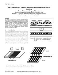
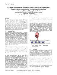
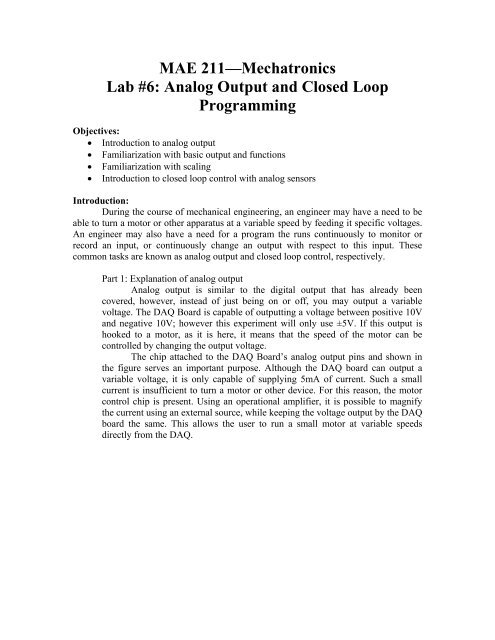
<strong>MAE</strong> 211—Mechatronics<strong>Lab</strong> <strong>#6</strong>: <strong>Analog</strong> <strong>Output</strong> <strong>and</strong> <strong>Closed</strong> <strong>Loop</strong>ProgrammingObjectives:• Introduction to analog output• Familiarization with basic output <strong>and</strong> functions• Familiarization with scaling• Introduction to closed loop control with analog sensorsIntroduction:During the course of mechanical engineering, an engineer may have a need to beable to turn a motor or other apparatus at a variable speed by feeding it specific voltages.An engineer may also have a need for a program the runs continuously to monitor orrecord an input, or continuously change an output with respect to this input. Thesecommon tasks are known as analog output <strong>and</strong> closed loop control, respectively.Part 1: Explanation of analog output<strong>Analog</strong> output is similar to the digital output that has already beencovered, however, instead of just being on or off, you may output a variablevoltage. The DAQ Board is capable of outputting a voltage between positive 10V<strong>and</strong> negative 10V; however this experiment will only use ±5V. If this output ishooked to a motor, as it is here, it means that the speed of the motor can becontrolled by changing the output voltage.The chip attached to the DAQ Board’s analog output pins <strong>and</strong> shown inthe figure serves an important purpose. Although the DAQ board can output avariable voltage, it is only capable of supplying 5mA of current. Such a smallcurrent is insufficient to turn a motor or other device. For this reason, the motorcontrol chip is present. Using an operational amplifier, it is possible to magnifythe current using an external source, while keeping the voltage output by the DAQboard the same. This allows the user to run a small motor at variable speedsdirectly from the DAQ.
Fig. 6-1—Motor control chipPart 2: Using the DAQ board’s analog output functionThe analog_out function in the mechlab toolbox requires two parameters,channel <strong>and</strong> voltage. The DAQ board has two analog output channels, <strong>and</strong> canaccept voltages ranging from -10V to +10V, <strong>and</strong> is accurate to approximately0.001V. This give much flexibility to specify exactly what the user needs.Aside from the analog_out function, a secondary function calledmotor_out has been written. The purpose of this function is to easily scale -5V to+5V to -100% to +100%. The reason for this is that this is a simpler way tocomm<strong>and</strong> the motor when using an encoder, as Matlab’s reaction time is too slowto accurately read the encoder if it is running much faster than 5V. It is importantto underst<strong>and</strong> that these comm<strong>and</strong>s are essentially the same, however, it isencouraged that you make use of the motor_out comm<strong>and</strong> as often as possible forsimplicity <strong>and</strong> avoidance of erroneous encoder readings. The motor_outcomm<strong>and</strong>, like the analog_out, requires two parameter, channel (1 or 2) <strong>and</strong> speed(-100 to +100).Part 3: ScalingMany sensors do not begin reading at 0 units of what they are measuring.For instance, the temperature sensors you will use in this lab will output a voltageof 0.01V/°F. However, the sensor has a base temperature reading of 70°F,meaning if you would get a reading of 0.01°F, the temperature is 71°F rather than1°F. For this reason, the sensor reading must be scaled using the line equationfrom basic Algebra:y=mx+b (1)Using this equation, the programmer can write a function to directlydisplay the meaning of the output, rather than a voltage that still needs to beinterpreted.
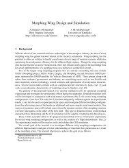
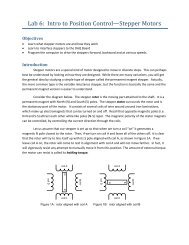
Part 4: <strong>Closed</strong> loop programmingA closed loop program is one that executes indefinitely until manuallystopped. In this lab, you will build a thermostat <strong>and</strong> a variable speed motor. Usingthe thermostat as an example, think of how a heating system works. A desiredtemperature is given, which is compared to the room temperature. If the roomtemperature is lower than the desired temperature, the heat turns on, but if it ishigher, the heat stays off. A person would not want to manually turn the heat onor off constantly to keep the room at the desired temperature, nor would theperson want to have to continuously tell the thermostat to check the temperature.In essence, this is closed loop control. An infinite loop is created, so that theprogram will run on its own, over <strong>and</strong> over, without any external intervention,aside from changing the desired setpoint. “Set it <strong>and</strong> forget it,” as they say.Experiments:Experiment 1: Using analog speed• Connect the motor to one of the motor outputs <strong>and</strong> turn it on using thesyntax motor_out(ch,speed). Change the speed several times <strong>and</strong>notice how the motor speed changes.Fig. 6-2—Motor connected to analog outputExperiment 2: Potentiometer• Hook the potentiometer to an analog input using the schematic below.The left terminal should be attached to the 5V power supply with a100Ω resistor in series, the right terminal should be grounded both tothe power supply <strong>and</strong> to the ground terminal on the analog input <strong>and</strong> tothe ground terminal on the power supply. The center terminal shouldbe connected to the positive terminal on the analog input.• Turn the power supply on <strong>and</strong> use an infinite loop to read thepotentiometer’s voltage continuously. Make sure that the values
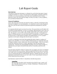
changes continuously from approximately zero to 5V. Make note ofthe min <strong>and</strong> max values observed here.Fig. 6-3—Potentiometer diagramExperiment 3: Variable speed• Using the potentiometer as a setpoint, write a program to continuouslyvary the speed of the motor with respect to the position of thepotentiometer. The motor should spin in reverse from -100 to 0 whilethe potentiometer is between 0 <strong>and</strong> 2V. The motor should remain offwhile the potentiometer reads between 2V <strong>and</strong> 3V. The motor shouldspin forward from 0 to +100 while the potentiometer reads between3V <strong>and</strong> 5V. You will need to using scaling for this part.Experiment 4: Reading RPM• Place an encoder <strong>and</strong> encoder wheel on your motor. Use this to readthe speed of you motor, <strong>and</strong> convert it to display the RPM of yourmotor every second, as the speed of the motor is varied.Fig. 6-4—Motor with encoder wheel
Project: Thermostat• Attach the temperature sensor to the analog input. Scale its output toprint the temperature in degrees. (See previous information on howthis sensor reads.)• Scale your potentiometer’s reading of 0 to 5V to be 70°F to 140°F• Connect a 100Ω resistor directly to the digital output, so that whenturned on it will heat up. CAUTION: THIS GETS HOT! Do not leavethis on long or the resistor will burn.• Using the temperature sensor to detect the temperature of the resistor,write a program so that the potentiometer can be used to give asetpoint, this setpoint will be compared to the temperature of theresistor, <strong>and</strong> the resistor will turned on or off according to thetemperature of the resistor compared to the setpoint temperature.Demonstrate this program to a TA.Fig. 6-5—ThermostatQuestions:1. (Experiment 1) (5 pts) Describe how the analog_out <strong>and</strong> the motor_out arerelated, <strong>and</strong> explain how the motor_out works, in relation to the analog_outcomm<strong>and</strong>.2. (Experiment 2) (5 pts) Why is the 100Ω resistor needed in the power line ofthis circuit?3. (Experiment 3)a. (5 pts) Show the calculations needed to scale the motor input versus thepotentiometer output.b. (5 pts) Tell why the input is not simply scaled, but a “space” called adeadb<strong>and</strong> is left in the center of the potentiometer input.4. (Experiment 4) (10 pts) Include your code for this program.
5. (Project)a. (12 pts) Include the code for this project.b. (6 pts) Show the calculations for scaling the temperature input.