Lab 6 Stepper Motor Control
Lab 6 Stepper Motor Control
Lab 6 Stepper Motor Control

Create successful ePaper yourself
Turn your PDF publications into a flip-book with our unique Google optimized e-Paper software.
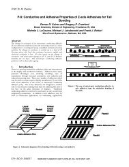
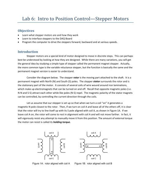
<strong>Lab</strong> 6: Intro to Position <strong>Control</strong>—<strong>Stepper</strong> <strong>Motor</strong>sObjectives• Learn what stepper motors are and how they work• Learn to interface steppers to the DAQ Board• Program the computer to drive the steppers forward, backward and at various speeds.Introduction<strong>Stepper</strong> motors are a special kind of motor designed to move in discrete steps. This can perhapsbest be understood by looking at how they are designed. While there are many variations, you will getthe general idea by studying a simple type of stepper called the permanent magnet stepper. Actually,the more common type is the variable reluctance stepper, but the function is basically the same and thepermanent magnet version is easier to understand.Consider the diagram below. The stepper rotor is the moving part attached to the shaft. It is apermanent magnet with North (N) and South (S) poles. The stepper stator surrounds the rotor and isthe stationary part of the motor. It consists of several coils of wire wound around iron laminations,which make up electromagnets that can be turned on and off. Recall that opposite magnetic poles (i.e.N‐N and S‐S) attract each other while like poles (N‐S) repel. The magnetic polarity of the stator magnetscan be controlled, by controlling the current direction through the coils.Let us assume that our stepper is set up so that when we turn a coil “on” it generates amagnetic N pole closest to the rotor. Then, if we turn on coil A and leave all of the others off, it is clearthat the rotor will try to line itself up with its S pole aligned with coil A, as shown in Figure 1A. If weleave coil A on, the rotor will come to rest in alignment with coil A and will not move farther. In fact, itwill vigorously resist any attempt to manually move it from this position. The amount of external torquethe motor can resist is called its holding torque.coil Acoil ASSNcoil Dcoil Dcoil Bcoil BNcoil CFigure 1A: rotor aligned with coil Acoil CFigure 1B: rotor aligned with coil B
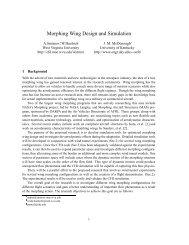
If we then turn off coil A and turn on coil B, the rotor will turn ¼ rotation to the right and align with coilB, as shown in Figure 1B. Continuing to rotate the magnetic field around the circle will cause the rotorto align next with coil C then coil D, etc. Each of these locations is a stable position. That is, as long asone of the coils is energized, the rotor will attempt to lock itself in alignment with that coil.<strong>Stepper</strong> ResolutionThe motor just described has only four stable positions, when operated in the full step mode. Itis easy to envision a need to have more options than this, and steppers are available with many morethan four steps per revolution. The ones you will be using in your lab have 100 steps per revolution, forexample. Many of the variations on the design of the stepper have been created with an eye toimproving the resolution and torque/speed characteristics of the motors. The invention of solid stateelectronic stepper controllers has made it possible to generate literally thousands of steps perrevolution from relatively simple stepper motors. One method for doing this is called half stepping andcan be done using your motors. Look again at Figure 1, and imagine that we control the coils in thefollowing way:1. Energize coil A and wait for the motor to come to equilibrium in alignment with coil A.2. Without turning off coil A, energize coil B. Assuming that the two coils generate equallypowerful magnetic fields, the rotor will come to rest halfway between coils A and B. It hasmoved exactly ½ step.3. Now turn off coil A, leaving only coil B energized, and the rotor will move on to align itself withcoil B.MicrosteppingThe same idea can be extended by the use of electronic current controls. Suppose instead of havingequal currents flowing in coil A and coil B, that the current in coil A were twice as large as the current incoil B. Now the rotor would come to rest a little more than ¼ of the way between A and B (tan ‐1 (0.5) =26.5 degrees). By controlling the relative strengths of the currents between two adjacent coils, the rotorcan be made to move in even smaller increments than the half steps described above.Unipolar/Bipolar WindingsThe motors you will use are unipolar. That means that you only have access to one end of eachwinding individually. Schematically, the motor windings look like Figure 2, with one wire being thecommon lead for all of the windings. It is possible using split power supplies and special controllers tocontrol the direction of current flow through these motors, but nobody would bother with that. In aunipolar motor, the positive supply voltage is usually fed to the common wire, and each of the windingsis then connected to a driver transistor, which acts as an on/off switch.
Bipolar motors are available which provide accessto both ends of each winding individually. These motorsallow relatively simple H‐bridge controllers to switch thedirection of the current through the windings, allowingeven more flexibility in the control of the motor, andoffering the possibility of achieving higher torque from agiven frame size. Returning to Figure 1, suppose thatwhile we were energizing coil A to be a North pole, wereversed the current in coil C and caused it to be a Southpole. Depending on the geometry of the motor and thestate of magnetic saturation of the rotor iron, additionaltorque might be derived from the motor in this way.CommonLeadCoil LeadsFigure 2: <strong>Stepper</strong> coil winding<strong>Lab</strong> Exercises: <strong>Stepper</strong> <strong>Control</strong> ProgramsConnect your motor to the interface board in the following way. Connect the black wire to +12V. Thenconnect the four colored wires to four successive digital outputs (“‐“ terminals) in the following order:brown, green, red, white. Recall that each of the digital outputs provides a path to the power supplyground when the output is turned on.To turn on a coil in the stepper motor, you need only to turn on the corresponding motor output. So thecommand digital_out(A,1) will turn on coil A, where “A” is the output to which you have wired thebrown wire. Likewise, digital_out(A+1,1) will turn on coil B through the green wire, etc. Use the digitaloutput commands to turn on and off the coils in the proper sequence to get the stepper to move. Trythis using Command Line inputs. Don’t forget to turn off coil A after turning on coil B, etc. When themotor is in a stable position, try to turn the shaft with your hand. The motor will resist surprisingly hardfor a little motor. The torque required to force the motor to move away from a stable position is calledthe holding torque and is one of the primary specifications for a stepper motor.Program 1: Forward and Reverse MotionKnowing that there are 100 full steps per revolution of the motor, write a program that will drive themotor one revolution clockwise and one revolution counterclockwise. Use the full‐ stepping mode. Puta piece of tape on the motor shaft as a “flag” to help you see how far the shaft has gone. Start bymaking a flow chart of your programming logic for making the program work.Hint: Don’t forget to turn off the coils at the appropriate times. Also, don’t forget that it willtake a finite amount of time for the stepper to move from one point to another, and that it willmove much slower than the computer can run through the program. You must insert some timedelay in the appropriate places or the motor will not be able to keep up. If the motion is erraticor it appears that steps are being skipped, you either have the coils out of sequence or you need
to insert more time. You can insert time delay by using the Matlab command pause(t ) where tis the amount of time in seconds you want the program to wait before executing the next step.Hint: You will probably want to use a for loop for this task. The general form of your loop willbeA = address;coil = A;for step = 1:100digital_out(coil,1);pause(p);coil = coil + 1;if coil >= A+4;coil = A;endend% address is the output number for coil A% default step size is 1 unless you specify it otherwise%coil is the output address for thecurrent coil% p is the amount of time to pause between steps%resets coil back to A for the cycle% end if statement% end forward for loopNOTE THAT THIS CODE WILL NOT WORK AS‐IS BECAUSE WE NEVER TURN OFF ANY OF THE COILS. It isjust given here to help you get started. Modify it to include turning off the correct coil at theappropriate time.Also note that the code above only counts up. You must add your own second loop or modify this oneto make the motor go backwards to its starting point.Also note that there are multiple ways to do this and the one shown here is simple to understand butnot particularly elegant. The whole business with the “if” statement can be eliminated by takingmodulo 4 of count: coil = mod(count,4); You are certainly free to make other improvements to theprogram, but be sure to properly comment your code so the T/A’s can understand it when they gradeyour lab.Program 2: Input from KeyboardFor motion control, we want to be able to tell the motor when to stop and which direction to go from aprogram or perhaps from the keyboard. Let’s use the keyboard as our input interface. Matlab canaccept input from the keyboard via the command “input(‘prompt’). Type help input for moreinformation on this command.Modify your first program to prompt the user for a number between ‐100 and 100, and use this numberto drive the motor that number of steps in the forward (n>0) or reverse directions, correspondingly.Hint: You can set up a for loop with a variable as the start point, the end point or the step size for thatmatter. So, for example, it is permissible to writefor j = P:Q:R %P, Q and R are integer variables. Q is the step size and can be negativedo stuff;endNote that P,Q, and R must have already been assigned values before you can call them in a loop like this.
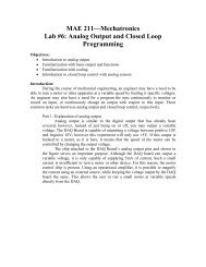
Program 3: Scaling I/OIn the real world, we deal in engineering units like millimeters and degrees, not in “steps”. Modify yourprogram so the user is prompted to enter the number of degrees to move, with the limit between ‐170and +170. Insert a math statement to convert the input to a number of steps for your program.Demonstrate your program to one of the T/A’s before going on. Save the code for your <strong>Lab</strong> Report.Program 4: Home PositionNext, we want to see how to make our robot go to a specific point in space. To do this, we must have areference position we call “home” or “zero” or “the origin”. For robots, this is usually called “home”.Use a rubber band or some tape or a dab of hot‐melt glue to fasten a Lego “beam” to your motor shaftso it sticks out like an arm. Set up the optical proximity sensor to detect when the end of the beam is inthe HOME position—see the diagram below. The optical sensor is wired as follows:Red: +5VBlack: 5V GroundOrange: Digital InputFor best accuracy, Home should always be approached from the same direction, since the beam hasfinite thickness >0. Robots always find home as the first thing they do when they are powered up.Modify your program so when it first starts, the motor is driven slowly in the clockwise direction untilthe optical sensor turns on. When the sensor turns on, the robot should stop moving and set itsposition counter to zero. We will use the convention that positive is counterclockwise and negative isclockwise.Lego beamTo digitalinput+5V<strong>Stepper</strong>motorOptical sensor emitsa beam of IR light anddetects it if it reflectsfrom objectGndF
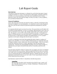
EndYStartFind HomePosition,disp(‘Ready’)Prompt forquit flagWanna quit?Final ProgramNow synthesize everything you have learned into onecomplete position control program. The programshould find home, then ask the user if they want toexit the program. If so, end. If not, ask for an anglebetween 0‐330 o and move the arm to that position.It should then go back and prompt for exit again, askfor a new position and go there, and just keep doingthis until the user gives the quit signal. Here is ageneral “outline” of what your program will look like.Note that each of these boxes has a significantamount of code inside. You should draw a moredetailed flow chart for each of the major elements ofthe program. Demonstrate your program to theT/As before disassembling your setup.NGet newpositionfromKeyboardHint: You can make your code more compact byusing the concept of position error. You know yourcurrent position. When you read a new positioncommand from the keyboard, compute the error:error = desired_angle – current angle;Calculate errorNow the error is a signed value that you can scale togive you the number of steps and the direction youneed to go to get to the new commanded location. Itcan be used directly in your for loop in a number ofways. A simple one would be as the end of thecounter:Is error zero?NMove motorto reduceerrorCalculate newerrorYnumsteps = floor(0.5 + abs(error)/3.6); % rounds tointegersteps = numsteps*sign(error); % sets directionfor count = 0:sign(error):stepsMove the motor; %you figure this out ☺endYou can do this in a simple, clunky way if you can’tfigure this out, but it’s rewarding to write nicecompact code when possible (and, it runs faster).
<strong>Lab</strong> Report• Write a an introduction summarizing the operation of stepper motors and showing a schematicof how you are controlling yours using the digital outputs.• Summarize each of the programs you have written. Describe the purpose of the program andbriefly describe the strategy you used to solve the problem. Include formatted and commentedsource code for each program.