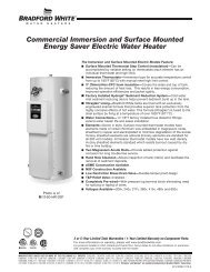
DIRECT VENT GAS WATER HEATER - Bradford White
DIRECT VENT GAS WATER HEATER - Bradford White
DIRECT VENT GAS WATER HEATER - Bradford White

You also want an ePaper? Increase the reach of your titles
YUMPU automatically turns print PDFs into web optimized ePapers that Google loves.
Water Connections continued-<br />
WARNING<br />
For protection against excessive temperatures and pressure, install<br />
temperature and pressure protective equipment required by local codes,<br />
but not less than a combination temperature and pressure relief valve<br />
certified by a nationally recognized testing laboratory that maintains<br />
periodic inspection of production of listed equipment or materials as<br />
meeting the requirements of the Standard for Relief Valves and<br />
Automatic Gas Shutoff Devices for Hot Water Supply Systems, ANSI<br />
Z21.22 and the Standard CAN1-4.4 Temperature, Pressure,<br />
Temperature and Pressure Relief Valves and Vacuum Relief Valves.<br />
The combination temperature and pressure relief valve must be marked<br />
with a maximum set pressure not to exceed the maximum working<br />
pressure of the water heater. The hourly BTU discharge capacity or the<br />
rated steam relief capacity of the combination temperature and pressure<br />
relief valve must not be less than the input rating of the water heater.<br />
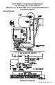
Install the combination temperature and pressure relief valve into the<br />
opening provided and marked for this purpose on the water heater.<br />
Note: Some models may already be equipped or supplied with a<br />
combination temperature and pressure relief valve. Verify that the<br />
combination temperature and pressure relief valve complies with local<br />
codes. If the combination temperature and pressure relief valve does<br />
not comply with local codes, replace it with one that does. Follow the<br />
installation instructions above on this page.<br />
Install a discharge line that terminates six (6) inches (15 cm) above the<br />
floor, or any distance below the structural floor, to the outlet of the<br />
combination temperature and pressure relief valve. DO NOT allow<br />
water from the discharge line to contact any live electrical part. The<br />
discharge line is to be installed to allow for complete drainage of both<br />
the combination temperature and pressure relief valve and the discharge<br />
line. The water from the discharge line must be directed to a suitable<br />
drain or area that will not be damaged by water Refer to “LOCATING<br />
THE <strong>WATER</strong> <strong>HEATER</strong>.” The discharge opening must not be subjected<br />
to blockage or freezing. DO NOT thread, plug or cap the discharge line.<br />
It is recommended that a minimum clearance of four (4) inches (10.2<br />
cm) be provided on the side of the water heater for servicing and<br />
maintenance of the combination temperature and pressure relief valve.<br />
Do not place a shutoff valve between the combination temperature and<br />
pressure relief valve and the water heater, or on discharge pipes<br />
between such valves or the atmosphere.<br />
15