DIRECT VENT GAS WATER HEATER - Bradford White
DIRECT VENT GAS WATER HEATER - Bradford White
DIRECT VENT GAS WATER HEATER - Bradford White

You also want an ePaper? Increase the reach of your titles
YUMPU automatically turns print PDFs into web optimized ePapers that Google loves.
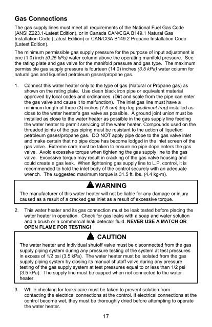
Gas Connections<br />
The gas supply lines must meet all requirements of the National Fuel Gas Code<br />
(ANSI Z223.1-Latest Edition), or in Canada CAN/CGA B149.1 Natural Gas<br />
Installation Code (Latest Edition) or CAN/CGA B149.2 Propane Installation Code<br />
(Latest Edition).<br />
The minimum permissible gas supply pressure for the purpose of input adjustment is<br />
one (1.0) inch (0.25 kPa) water column above the operating manifold pressure. See<br />
the rating plate and gas valve for the manifold pressure and gas type. The maximum<br />
permissible gas supply pressure is fourteen (14.0) inches (3.5 kPa) water column for<br />
natural gas and liquefied petroleum gases/propane gas.<br />
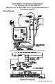
1. Connect this water heater only to the type of gas (Natural or Propane gas) as<br />
shown on the rating plate. Use clean black iron pipe or equivalent material<br />
approved by local codes and ordinances. (Dirt and scale from the pipe can enter<br />
the gas valve and cause it to malfunction). The inlet gas line must have a<br />
minimum length of three (3) inches (7.6 cm) drip leg (sediment trap) installed as<br />
close to the water heater’s gas valve as possible. A ground joint union must be<br />
installed as close to the water heater as possible in the gas supply line feeding<br />
the water heater to permit servicing of the water heater. Compounds used on the<br />
threaded joints of the gas piping must be resistant to the action of liquefied<br />
petroleum gases/propane gas. DO NOT apply pipe dope to the gas valve inlet<br />
and make certain that no pipe dope has become lodged in the inlet screen of the<br />
gas valve. Extreme care must be taken to ensure no pipe dope enters the gas<br />
valve. Avoid excessive torque when tightening the gas supply line to the gas<br />
valve. Excessive torque may result in cracking of the gas valve housing and<br />
could create a gas leak. When tightening gas supply line to L.P. control, it is<br />
recommended to hold the inlet body of the control securely with an adequate<br />
wrench. The suggested maximum torque is 31.5 ft. lbs. (4.4 kg-m).<br />
WARNING<br />
The manufacturer of this water heater will not be liable for any damage or injury<br />
caused as a result of a cracked gas inlet as a result of excessive torque.<br />
2. This water heater and its gas connection must be leak tested before placing the<br />
water heater in operation. Check for gas leaks with a soap and water solution<br />
and a brush or a commercial leak detector fluid. NEVER USE A MATCH OR<br />
OPEN FLAME FOR TESTING!<br />
CAUTION<br />
The water heater and individual shutoff valve must be disconnected from the gas<br />
supply piping system during any pressure testing of the system at test pressures<br />
in excess of 1/2 psi (3.5 kPa). The water heater must be isolated from the gas<br />
supply piping system by closing its manual shutoff valve during any pressure<br />
testing of the gas supply system at test pressures equal to or less than 1/2 psi<br />
(3.5 kPa). The supply line must be capped when not connected to the water<br />
heater.<br />
3. While checking for leaks care must be taken to prevent solution from<br />
contacting the electrical connections at the control. If electrical connections at the<br />
control become wet, they must be thoroughly dried before attempting to operate<br />
the water heater.<br />
17