TELORVEK II TP-50A TPI Fuel Injection Systems - Ron Francis Wiring
TELORVEK II TP-50A TPI Fuel Injection Systems - Ron Francis Wiring
TELORVEK II TP-50A TPI Fuel Injection Systems - Ron Francis Wiring

Create successful ePaper yourself
Turn your PDF publications into a flip-book with our unique Google optimized e-Paper software.
Page #6<br />
CANISTER PURGE: The purge solenoid is controlled by the ECM and allows ported manifold vacuum to purge the<br />
vaporsfrom the canister. Canister Purge: Plug in the red connector with the PINK & DK GREEN wires into the<br />
canister purgesolenoid and run the wires back to the Telorvek panel.<br />
Connect the three PINK wires to the Telorvek panel as follows:(PURGE SOL A->3) to #3, (DIVERT SOL A->5)<br />
and(AIR PORT SOL A->5) both wires connect to #5. Connect the DK GREEN wire (PURGE SOL B->38) to<br />
#38, BLACK (DIVERT SOL B->40) to #40 and BROWN (AIR PORT B->39) to #39.<br />
VEHICLE SPEED SENSOR (VSS): A VSS signal input is needed on all General Motors <strong>TP</strong>I engines. If the ECM does not see<br />
that input a CODE 24 WILL SET The VSS input helps control some of the EGR and IAC functions. You need to provide<br />
this input and prevent this code one of two ways.<br />
Using a 700 R4 Transmission The first is most 700 R4 transmissions have the factory pulse generator located in them.<br />
This can be connected into the computer to provide this signal. For the 700 R4 transmission that has a speedometer cable<br />
connector we have developed a pulse generator (part #PG-6A) that installs in line on the cable to provide the speed signal<br />
into the computer. This transmission also requires a torque converter lock-up signal which is given by the ECM from the<br />
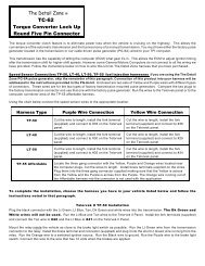
input it receives from the pulse generator. The Detail Zone TC-60 wiring kit includes the wiring for the TCC lock-up and the<br />
correct connectors to plug into the factory pulse generator to make this connection easy.<br />
Other Transmissions A speed signal into the computer can done simply by purchasing the PG-6A pulse generator. It<br />
installs into the speedometer cable and following the instructions will wire into the harness. If you would like to wire the<br />
VSS circuit yourself, terminal #35 is the VSS low (ground side), #36 is the VSS high (signal) and if you have an electric<br />
speedometer terminal #37 is for that connection.<br />
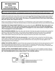
700R4 Transmission Panel Connections The Detail Zone offers a wiring kit (TC-60) for the 700R4 transmission which<br />
allows the computer to control torque converter lock-up. If you would like to wire in this circuit yourself, terminal #41 is the<br />
high gear switch and terminal #42 is the torque converter lock-up control.<br />
Cold Start Injectors Some GM fuel injection engines have a ninth injector used for cold starting. <strong>Wiring</strong> your vehicle as a<br />
1990 does not require this injector to be connected. The 1990 engine computer allows more fuel to the engine during cold<br />
starts. The injector as well as the sensor for the ninth injector mounted on the front of the engine can be removed and<br />
plugged or left in place un-connected.<br />
Final Hookups<br />
Connect the large prewired ORANGE wire to the ignition circuit of your ignition switch. This is an ignition feed that is<br />
controlled by the ignition switch. This is not an accessory feed and must remain hot even when the engine is<br />
cranking. Connect the large prewired RED battery feed wire to a battery feed. This is a battery feed that must<br />
remain hot even with the key off. Make sure this is a good connection. If you have a Master Disconnect switch, install<br />
this wire on the battery side of the switch so it will remain hot with the Master Disconnect turned off. The<br />
BLACK ground wire from the <strong>TELORVEK</strong> <strong>II</strong> Panel runs direct to the battery. Do not consider grounding the battery<br />
to the frame and then the engine to the frame. Run the battery ground directly to the engine.<br />
If you turn the key on but do not crank engine, you will hear the fuel pump for about 2 to 4 seconds before it stops.<br />
This will indicate the pump is ready. During normal operating it is best if you do not wait till the pump stops as this is not<br />
an indication that the pressure is up. There is no need to "pump" the throttle on fuel injection cars.<br />
You have now completed the kit installation. You may have noted empty terminals on the Telorvek panel that do not<br />
have any wire connections to them. The Detail Zone runs all computer connections out of the computer plug(s) even if<br />
they are not used in aftermarket applications.<br />
Other Harness Connections: The Detail Zone offers a CF-29 cooling fan and A/C request wiring kit for connecting into<br />
an electric radiator cooling fan as well as into the A/C circuit to raise the engine idle when the A/C compressor is on. If you<br />
would like to wire these items yourself, the necessary wires have been run out of the computer plug to terminals on the<br />
Telorvek panel.