product installation instructions - Ron Francis Wiring
product installation instructions - Ron Francis Wiring
product installation instructions - Ron Francis Wiring

Create successful ePaper yourself
Turn your PDF publications into a flip-book with our unique Google optimized e-Paper software.
CC-57<br />
Cruise Control One<br />
Touch Activation Relay<br />
This <strong>product</strong> has been designed to operate Rostra Electronic Cruise Control System part #250-1223 (<strong>Ron</strong> <strong>Francis</strong><br />
<strong>Wiring</strong> part number CC-60) only. Do not attempt to connect this kit to any other type of cruise control system.<br />
Installing this kit allows the cruise control unit to be set using one of <strong>Ron</strong> <strong>Francis</strong> <strong>Wiring</strong> push button column dress up<br />
levers or momentary dash mounted push button type switch. NOTE: This <strong>product</strong> allows control of the set and<br />
coast functions of the cruise control system. The resume or accelerate functions of the cruise control system<br />
WILL NOT operate when using this relay kit.<br />
Refer to the <strong>installation</strong> <strong>instructions</strong> provided with our CC-60 Electronic cruise control system for all <strong>installation</strong> and<br />
trouble shooting questions. Follow the instruction below to connect the relay system into the cruise control wire harness.<br />
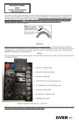
MOUNTING THE TOGGLE ON/OFF SWITCH: Mount the switch in the dash. IMPORTANT: Mount this switch in an<br />
accessible location. This is the cruise control systems on/off switch and is your secondary disengagement<br />
switch. In the event your brake light switch failed to disengage the cruise control system, turning this switch<br />
off will disengage the cruise control system.<br />
RELAY MOUNTING &WIRING: Mount the relay under the dash. The relay has a green and yellow wires running from<br />
it going to a white four gang connector. This connector has an additional red and brown wires which is addressed<br />
later in these <strong>instructions</strong>. This connector mates into the control switch wire harness connector running from the<br />
cruise control system making sure the same color wires are across from each other in the connector.<br />
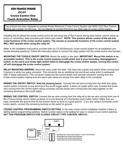
WIRING THE ON/OFF SWITCH: Note the drawing below. Connect the red wire running from the white four gang<br />
control switch connector to one terminal of the on/off toggle switch. It does not matter which one. Connect the brown<br />
wire running from the control switch wiring connector and the brown wire running from the relay together on the<br />
remaining terminal on the on/off switch.<br />
WIRING THE CONTROL SWITCH: Connect the tan wire running from the relay kit to the tan wire running from one of<br />
<strong>Ron</strong> <strong>Francis</strong> wiring column dress up levers or to one terminal of a momentary push button switch. Make sure you<br />
have connected the ground wire for the column dress up lever to a good ground. If you are using a momentary push<br />
button switch, connect the remaining terminal on the switch to ground.<br />
CRUISE CONTROL PROGRAMMING SWITCH SETTING: In the main cruise control <strong>installation</strong> booklet it refers to<br />
setting twelve programming switches. Switch number twelve is the setting for open or closed circuit control switches.<br />
SET THIS PROGRAM SWITCH FOR CLOSED CIRCUIT TYPE CONTROL SWITCH.
© Copyright 2005 <strong>Ron</strong> Frrancis' (REVISED 11/17/05) P:\INST\cc-57