product installation instructions - Ron Francis Wiring
product installation instructions - Ron Francis Wiring
product installation instructions - Ron Francis Wiring

Create successful ePaper yourself
Turn your PDF publications into a flip-book with our unique Google optimized e-Paper software.
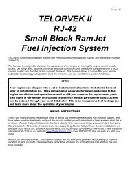
Page #1TELORVEK EFI5 .0,5.8Fue1 994-96FordTruck&LlInj e ctio nS ystemi g h tin g(ML-95)WIRING INSTRUCTIONSThank you for purchasing the absolute finest of wiring kits for the Ford Motor Co. fuel injection engine.We have taken considerable time to work out the circuitry so that you, the customer will understand atleast some of what this is all about. We ask that you follow our <strong>instructions</strong> closely. We recommend usinga high pressure in tank fuel (45 PBS min.) pump. Custom <strong>installation</strong>s are available from Tanks Inc.(phone #320-558-6882) and Rock Valley (phone #800-344-1934). There are some valuable HOW -TO’son our website (www.thedetailzone.com) under PROJECTS that can help you with your install.Should you eliminate a sensor, your injection system will not work at its peak and will probably be in somevariation of back up mode. There are many factors that will help you get a trouble free start up that youmust consider.NOTE!!FORD diagnostic procedures are very detailed, lengthy and impossible to cover in this set of<strong>instructions</strong>. Purchasing the FORD ENGINE/ EMISSIONS DIAGNOSIS shop manual will helpyou learn about the engine you installed and guide you through the correct diagnosticprocedures Ford recommends. This book is available through your local Ford dealer or HelmInc. Helm is the distributor for the shop manuals for General Motors and Ford Motor Company.Helm can be contacted at 800-782-4356 or on their web site www.helminc.comWARNING!After the kit <strong>installation</strong> is complete and it is necessary to diagnose a startingor drive ability problem, follow the procedures recommended in the shopmanual. All voltage tests must be preformed using a HIGH impedance, digitalvoltmeter. DO NOT use a test light on this system! DAMAGE WILL BE DONEto the engine computer if a test light is used on this system.STARTING INSTALLATIONSince there are so many individual circuits to complete, we recommend that you connect them in the orderthat we prescribe. Disconnect the battery before starting and do not reconnect until instructed.There will be many connections to the TELORVEK panel so plan the location of the panel in an area withroom to work. We suggest mounting the panel in an assessable location, in the trunk, under the seat orunder the dash are good. In order to allow for the proper spacing between the computer and the Telorvekpanel, plug the connector into the computer (ECM) and mount the panel and computer. For safety,disconnect the ECM connector until finished the <strong>installation</strong>. A poor <strong>installation</strong> will result in a poorrunning car. The number referred to from this point on will be the location on one of the terminalblocks located on the TELORVEK panel.
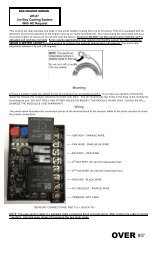
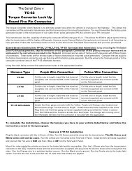
Page #2Always put the first terminal under a screw with the fat wire side down as in thedrawing. Install any second terminals just the opposite as this will allow the screw tohold squarely and tight. The insulation from one terminal should not interfere with theone next to it.Use a crimping tool that is designed for insulated terminals. If the tool punctures theinsulation (plastic) or damages it in any way, you are using the wrong tool. The proper tool will only"flatten" the plastic and if the handles are squeezed completely, the proper crimp has been made. Get inthe habit of test pulling at each terminal as you crimp it to the wire.After all wires are connected to the engine, wire tie them together or use 3/4 inch Zip loom to protect them.This can be done before any connections are made to the panel. Since all wires are marked, running theentire group to the panel at one time is fine. Some terminals on the panel may not be used!*******Important! We have supplied three sizes of terminals for your use on the panels itself. The Yellow is usedon the 10-12 gauge wire, Blue is used on 14-16 gauge wire and Red is used for the bulk of the smallerwires. Each individual bag <strong>instructions</strong> will be marked as to when to use the yellow or blue, terminals, allother wires will use the red terminals. NOTE You will be moving around to different terminals on the TELORVEK panel tomake connections. For this reason extra care is needed when making allconnections to the panel. NOTE If you have a 1996 model engine/transmission and your ECM uses a 104 pinconnection you cannot use this ECM with this wiring kit. You will need toacquire a 1995 Ford Truck/Bronco that matches your engine size andtransmission.
Page #3InjectorsTwo different wiring scenarios are listed below. Based on the part of countryyou live in as well as the engine and transmission you are using, the correctinjector harness wiring bag has been supplied. Look at the bag numbersupplied in your kit and follow the paragraph below that pertains to that bag.Always follow the printing on the wires themselves!!Bag #20. INJECTORS 5.0 automatic transmission or 5.8 California emissions: The injector wiring ismade up in a harness with two branches, one branch for the left side (drivers side) injectors and one forthe right side injectors. Locate the right side injector connectors (injectors 1 through 4) and lay them outon the manifold. Now lay the left side injector (5 through 8) connectors out on the manifold. Note theprinting on the wires running from the injector connectors making sure the correct connectors are pluggedonto the correct injectors: red & tan to INJ 1, red & white to INJ 2, red & brown to INJ 3, red & lt blue to INJ4, red & black to INJ 5, red & lt green to INJ 6, red & purple to INJ 7 and red and dk blue to INJ 8.Now run the wires back to the panel. Connect the reds INJ 1->7 and INJ 5->7 to #7. Connect the tan INJ1->100 to #100, white INJ 2->101 to #101, brown INJ 3->102 to #102, lt blue INJ 4->103 to #103, blackINJ 5->104 to #104, lt green INJ 6->105 to #105, purple INJ 7->106 to #106 and dk blue INJ 8->107 to#107.Bag #20A. INJECTORS 5.0 manual transmission or 5.8 standard emissions: The injector wiring ismade up in a harness with two branches, one branch for the left side (drivers side) injectors and one forthe right side injectors. Locate the right side injector connectors (injectors 1 through 4) and lay them outon the manifold. Now lay the left side injector (5 through 8) connectors out on the manifold. Note theprinting on the wires running from the injector connectors making sure the correct connectors are pluggedonto the correct injectors: red & tan to INJ 1, red & white to INJ 2, red & white to INJ 3, red & tan to INJ 4,red & tan to INJ 5, red & white to INJ 6, red & white to INJ 7 and red and tan to INJ 8.Now run the wires back to the panel. Connect the reds INJ 1->7 and INJ 2->7 to #7. Connect the tanINJECTORS->100 to #100 and the white INJECTORS->101 to #101.Bag #21. IGNITION COIL: The ignition coil is mounted on the rear of the intake manifold. Plug in theconnector and run the wires back to the Telorvek panel. Using blue terminals connect the red wire (IGNCOIL->10) to #10 and using red terminals connect the purple wire (IGN COIL->12) to #12.Bag #22. COOLANT TEMPERATURE SENSOR: After attaching the plug to the sensor located on thetop front of the motor next to the distributor run the two wires to the panel. Using the red terminals,connect the lt green wire (ECT->15) to #15 and the gray wire (ECT->94) to #94.Bag #23. INTAKE AIR TEMPERATURE SENSOR (IAT): Plug the connector onto the IAT sensor and runthe wires to the Telorvek Panel. Using the red terminals connect the yellow wire (IAT->16) to #16 and thegray wire (IAT->94) to #94.Bag #24. IDLE SPEED CONTROL: The ISC is located on the top front of the throttle body. Plug in theconnector and run the wires back to the panel. Using the red terminals, connect the white wire (ISC->17)to #17 and the red wire (IAC->8) to #8.
Page #4Bag #25. THROTTLE POSITION SENSOR (TPS): Plug the connector into the sensor located in thethrottle body and run the wires back to the panel. Using the red terminals connect the brown (TPS->36) to#36, white (TPS->38) to #38 and gray (TPS->96) to #96.Bag #26. EXHAUST GAS RECIRCULATION VALVE POSITION SENSOR (EGRVP): Plug the connectoronto the EGRVP. Using red terminals run the lt green wire (EGRVP->39) to #39, brown wire (EGRVP->36)to #36 and the gray (EGRVP->96) to #96.Bag #27. IGNITION CONTROL MODULE CONNECTION: The ICM requires some of the wires to beshielded from any electrical interference, that is why three of the wires (pink, gray, solid strand) in theconnector are wrapped.Carefully uncoil the harness and plug it into the ICM then run all the wires to the Telorvek panel. Removethe tape and shielding material back only as far as it is necessary for the length of the wire to be cut andallowing enough wire to make the connections on the panel. In the shielded harness there is a solid strandwire with no insulation. Install a blue terminal on it and connect it to #26. After the connection is madewrap the exposed wire from the shielded harness to #26 with electrical tape. Using red terminals the othertwo wires in the shielded harness are connected as follows, pink (ICM->19) to #19 and gray (ICM->20) to#20. Connect the four remaining wires running from the ICM connector as follows: purple (ICM->12) to#12, red (ICM->10) to #10, black (ICM->25) to #25 and purple (ICM->18) to #18.If you are installing a tach in your vehicle, connect the purple wire 13->TACH to #13 and run the wire tothe tach. Follow the tach manufactures <strong>installation</strong> <strong>instructions</strong> on the wiring of this instrument.Bag #28 DISTRIBUTOR: The distributor wiring requires the wires to be shielded from any electricalinterference, that is why the orange, gray and solid strand in the connector are wrapped.Carefully uncoil the harness and plug it into the distributor then run all the wires to the Telorvek panel.Remove the tape and shielding material back only as far as it is necessary for the length of the wire to becut and allowing enough wire to make the connections on the panel. In the shielded harness there is asolid strand wire with no insulation, install a blue terminal on it and connect it to #26. After the connectionis made wrap the exposed wire from the shielded harness to #26 with electrical tape. Using red terminalsare connect the remaining wires in the shielded harness as follows, orange (DIST->21) to #21 and gray(DIST->20) to #20. Now connect the black wire (DIST->25 to #25 and the red wire (DIST->9) to #9.
Page #5Oxygen Sensor(s)Three different wiring scenarios are listed below. Based on the part of country you live in as well asthe engine and transmission you are using the correct o2 sensor wiring bag has been supplied. Lookat the bag number supplied in your kit and follow the paragraph below that pertains to that bag.Always follow the printing on the wires themselves!!Bag #29. OXYGEN SENSOR 94-95 5.0 w/E4OD automatic transmission: This area of the vehicle ishot so keep the wires away from the exhaust. Install the sensor as close to the block as possible. Plugin the connector into the O2 sensor and run the wires to the Telorvek panel. Using the red terminalsconnect the red wire (02 SENSOR->11) to #11 and the black wire (O2 SENSOR->28 to #28. Connect thelt blue (O2 SENSOR->22) to #22 and the orange wire (O2 SENSOR->92) to #92.Bag #29A. OXYGEN SENSOR 95 5.0 w/4R70W automatic transmission or 94-95 5.8 w/automatic ormanual transmission with standard emissions: This area of the vehicle is hot so keep the wires awayfrom the exhaust. Install the sensor as close to the block as possible. Plug in the connector into theO2 sensor and run the wires to the Telorvek panel. Using the red terminals connect the red wire (02SENSOR->11) to #11 and the black wire (O2 SENSOR->28 to #28. Connect the lt blue (O2 SENSOR->99) to #99 and the orange wire (O2 SENSOR->92) to #92.Bag #29B. OXYGEN SENSORS (2) 94-95 5.8 automatic or manual transmission w/Californiaemission: This area of the vehicle is hot so keep the wires away from the exhaust. Install the right andleft side o2 sensors in the exhaust system as close to the block as possible. After the sensors areinstalled, plug the connector with the dk blue, red, gray and black into the left sensor. Plug the connectorwith the black, gray, lt blue and red wires into the right o2 sensor and run all the wires back to the panel.Using the red terminals connect the red wires (LEFT 02 SEN->11) and the (RIGHT O2 SEN->11) to #11.Connect the black wire (RIGHT O2 SEN->28) to #28 and the other black wire (LEFT O2 SEN->27) to #27.Connect the lt blue (RIGHT O2 SEN->22) to #22, gray (RIGHT O2 SEN->95) to #95, dk blue (LEFT O2SEN->83) to #83 and the gray (LEFT O2 SEN->95) to #95.Bag #30 MANIFOLD ABSOLUTE PRESSURE SENSOR (MAP) 5.0,5.8 engine w/manual transmissionand standard emission only: Mount the MAP sensor in the engine compartment. Plug in the connectorand run the wires back to the panel. Connect the brown wire (MAP->37) to #37, black (MAP->40) to #40and gray (MAP->95) to #95.Bag #30A MASS AIR FLOW SENSOR (MAF) 5.0 engine w/automatic transmission or 5.8 enginew/California emission: Mount the MAF sensor in the air inlet tube between the air filter and throttle body.Plug in the connector and run the wires back to the panel. Using the blue terminals connect the black wire(MAF->27) to #27 and the red MAF->8 to #8. Using the red terminals connect the tan (MAF->46) to #46and the lt blue (MAF->47) to #47.
Page #6VIP diagnostic connectorTwo different wiring scenarios are listed below. Based on the part of country you live in as well as theengine and transmission you are using the correct VIP wiring bag has been supplied. Look at the bagnumber supplied in your kit and follow the paragraph below that pertains to that bag.Always follow the printing on the wires themselves!!Bag #31. V.I.P. SELF TEST 5.0 w/manual transmission or 5.8 w/standard emission: Mount bothconnectors inside the vehicle under the dash and run the wires to the Telorvek Panel. Using the redterminals connect the tan (VIP 1->46) to #46, tan (VIP 1->48 to #48, gray (VIP 1->97) to #97, lt green (VIP1->44) to #44, lt blue (VIP 1->41) to #41 and the white (VIP 2->45) to #45.The remaining lt Green & red wires are for the dash mounted service engine soon (S.E.S) light. The lightmust be a two wire un-grounded light. Connect the lt green wire (44->SES LT) to #44 on the TelorvekPanel and run it to a dash indicator light and connect it to one of the wires running from the light. The redwire (65->SES LT) connects to #65 on the panel and run to the other wire running from the light. This lightis not required as the yellow light on top of the Telorvek Panel has the same function.Bag #31A. V.I.P. SELF TEST 5.0 w/automatic transmission or 5.8 w/California emission: Mount bothconnectors inside the vehicle under the dash and run the wires to the Telorvek Panel. Using the redterminals connect the tan (VIP 1->42) to #42, gray (VIP 1->97) to #97, pink (VIP 1->43) to #43, lt green(VIP 1->44) to #44, lt blue (VIP 1->41) to #41 and the white (VIP 2->45) to #45.The remaining lt Green & red wires are for the dash mounted service engine soon (S.E.S) light. The lightmust be a two wire un-grounded light. Connect the lt green wire (44->SES LT) to #44 on the TelorvekPanel and run it to a dash indicator light and connect it to one of the wires running from the light. The redwire (65->SES LT) connects to #65 on the panel and run to the other wire running from the light. This lightis not required as the yellow light on top of the Telorvek Panel has the same function.
Page #7Transmission <strong>Wiring</strong> & InstructionsAutomatic Electronic Transmission <strong>Wiring</strong>Three different wiring scenarios are listed below. Based on the part of country you live in as well asthe engine and transmission you are using the correct transmission wiring bag has been supplied.Look at the bag number supplied in your kit and follow the paragraph that pertains to that bag.Always follow the printing on the wires themselves!!Manual TransmissionsW iring bags #32, #33 and #35 are not supplied with this type transmission. W iring bag #34 vehiclespeed sensor still must be installed to provide the engine computer with a speed signal input.Bag #32. E4OD TRANSMISSION CONNECTIONS 5.0 engine or 95 5.8 engine w/California emission:The E4OD transmission is a electronically controlled four speed automatic transmission. Plug theconnector into the transmission and run the wires to the Telorvek panel. Using the red terminals, connectthe orange wire (TRANS 7->70) to #70, yellow (TRANS 4->73) to #73, brown (TRANS 5->71) to #71, gray(TRANS 8->98) to #98, orange (TRANS 3->74) to #74, pink (TRANS 2->72) to #72 and the white (TRANS11->75 to #75 . Using blue terminals, connect the red (TRANS 1->67) and the red (TRANS 12->67) to#67.The Purple wire (77->BRK SW) connects to #77 and runs to the cold side of the brake light switch. Thiswire should only have 12 volts with the brake pedal depressed.Bag #32A. E4OD TRANSMISSION CONNECTIONS 94-95 5.8 engine w/standard emission: The E4ODtransmission is a electronically controlled four speed automatic transmission. Plug the connector into thetransmission and run the wires to the Telorvek panel. Using the red terminals, connect the orange wire(TRANS 7->85) to #85, yellow (TRANS 4->73) to #73, brown (TRANS 5->71) to #71, gray (TRANS 8->98)to #98, orange (TRANS 3->72) to #72, pink (TRANS 2->43) to #43 and the white (TRANS 11->75 to #75 .Using blue terminals, connect the red (TRANS 1->67) and the red (TRANS 12->67) to #67.The Purple wire (77->BRK SW) connects to #77 and runs to the cold side of the brake light switch. Thiswire should only have 12 volts with the brake pedal depressed.Bag #32B. 4R70W TRANSMISSION CONNECTIONS 95 5.0 engine: The 4R70W transmission is aelectronically controlled four speed automatic transmission. Plug the connector into the transmission andrun the wires to the Telorvek panel. Using the red terminals, connect the orange wire (TRANS 5->92) to#92, yellow (TRANS 3->73) to #73, white (TRANS 10->75) to #75, gray (TRANS 9->98) to #98, orange(TRANS 1->74) to #74 and the pink (TRANS 6->72) to #72. Using blue terminals, connect the red(TRANS 8->67), red (TRANS 7->67) to #67 and the red (TRANS 2->68) to #68.The Purple wire (77->BRK SW) connects to #77 and runs to the cold side of the brake light switch. Thiswire should only have 12 volts with the brake pedal depressed.The remaining two gang connector is for the output shaft speed sensor located in the tail shaft of thetransmission. After plugging in the connector run the wires to the panel. Connect the gray wire (SHAFTSPD SEN->98) to #98 and the dk green wire (SHAFT SPD SEN->84) to #84.
Page #8Bag #33. TRANSMISSION CONTROL SWITCH (TCS) & TRANSMISSION CONTROL INDICATORLIGHT (TCIL): The ECM has the capability to lock-out fourth gear of the transmission with a push of abutton. Pushing the momentary contact TCS button will light and blink the TCIL and lock-out fourth gearin the transmission for city driving. Pushing the button again will turn the TCIL off and release the lock-outallowing the transmission to shift into fourth gear for highway driving.Mount a momentary contact switch in dash or near the shifter lever. Connect the red wire (66->TCS) to#66 and the tan wire (79->TCS) to #79 and run both wires to the TCS switch. You may connect the wiresto either terminal on the switch.The TCIL light must be a two wire un-grounded light. Mount the light in the dash where it is visible whiledriving. Connect the white wire (78->TCIL) to #78 and the red wire (66->TCIL) to #66 and run both wires tothe TCIL light and make the connections.Bag #34. VEHICLE SPEED SENSOR: On a stock vehicle application the rear anti-lock brake sensorsends a signal to the programmable speedometer/odometer module (PSOM). The module then convertsthis signal into a standard 8000 pulses per mile (8 pulses per revolution) signal all Ford ECM'S accept. Inorder for the transmission to function properly this signal must be provided to the ECM.Speedometer cable driven eight pulse generators (PG-8) are available however will have to be adapted toyour speedometer cable. This service can be preformed at your local speedometer shop.If you discussed using a manual or non-electronic transmission at the time of order we have applied thetypical Ford speed sensor connector to the proper wires. You can connect this to Ford Speed Sensor partnumber: E9TZ-9E731-A. This sensor can be adapted to most C4, C6, AOD and manual transmissions.After mounting the generator connect the (VSS HIGH->80) to #80 and run it to the signal output wire fromthe generator. Connect the (VSS LOW->28) wire to #28 and run it to the VSS low output wire from thegenerator. Some aftermarket generators require an ignition feed to the unit. If so connect it can beconnected to #8 on the panel.Bag #35. MANUAL LEVER POSITION SWITCH (MLPS) : The manual lever position switch is located onthe left hand side of the transmission. The MLPS controls neutral safety, back-up and lever positionfunctions. W e have included wires in the MLPS connector to allow you to get full use out of the switch.Connect the circuits in the switch as follows:NEUTRALB ACKL EVERP OSThe heavier gauge Lt Blue (IGNITION SW->) and the Purple (START SOL->) wiresare for the neutral safety circuit. Locate the wire that runs from the ignition switch to the starter solenoid.Cut the wire and connect the Lt Blue wire (IGNITION SW->) to the wire running from the ignition switchand the Purple wire (START SOL->) to the wire running from the starter solenoid. NOTE: If you are wiringthis circuit to one of our Component Panel wiring kits, these wires will be a color for color match./SAFETY-UPL IGHTS::Connect the dk Green wire (BACK UP LT FEED) to a 12 volt ignition source. Thiswire should have 12 volts only with the key in the run position. Run the other dk Green wire (TO BACK UPLTS) to the rear of the vehicle and connect it to both back-up lights. The lights must be grounded.: Run the yellow and gray wires to the Telorvek panel. Using the redterminals, connect the yellow wire (MLPS->76) to #76 and the gray wire (MLPS->97) to #97.ITIONCIRCUITBag #36. FUEL PUMP, INERTIA SWITCH & FUEL PUMP RELAY: We have included the wiringnecessary for the Ford inertia switch. The inertia switch cuts off the electric fuel pump in the advent of anaccident. Mount the inertia switch in the rear of the vehicle in a dry area. Plug the connector into the inertiaswitch. Using the blue terminals connect the tan wire (INERTIA SW->81) to #81 on the Telorvek panel.Run the other tan wire (INERTIA SW->PUMP) to the electric fuel pump. Hook the wire to the positiveterminal on the pump. From the negative terminal on the pump connect a wire and run it to a goodground.
Page #9NOTE: The inertia switch has a red button on top of it that must be set (pushed down) in order for the fuelpump to operate. If the pump fails to operate check the inertia switch making sure the red button is in thedown position.FUEL PUMP RELAY: The fuel pump relay is located in the cover of the TELORVEK panel and is prewired.A relay must be installed in the connector (GM part #14100455) or the pump WILL NOT operate.Emission Control <strong>Wiring</strong>Two different wiring scenarios are listed below. Based on the part of country you live in as well as theengine and transmission you are using the correct emission control wiring bag has been supplied.Look at the bag number supplied in your kit and follow the paragraph below that pertains to that bag.Always follow the printing on the wires themselves!!Bag #37. EGR SOLENOID (EGR), AIR DIVERT & AIR BYPASS SOLENOIDS, CANISTER PURGESOLENOID 5.0 engine w/automatic transmission or 5.8 engine w/California emission:EGR: Plug the connector into the EGR solenoid. Using the red terminals run the red wire (EGR SOL->6)to #6 and the brown wire (EGR SOL->49) to #49.AIR DIVERT & AIR BYPASS SOLENOIDS: Controlled by the ECM, these solenoids control the fresh airflow into the exhaust reducing the hydrocarbon and carbon monoxide content of the exhaust.BYPASS SOLENOID: Plug the connector into the bypass solenoid and run the wires to the panel. Usingthe red terminals connect the red wire (BYPASS SOL->5) to #5 and the white wire (BYPASS SOL->51) to#51.AIR DIVERT SOLENOID: Plug the connector into the air divert solenoid and run the wires to the panel.Using the red terminals, connect the red wire (DIVERT SOL->6) to #6 and the brown wire (DIVERT SOL->50) to #50.CANISTER PURGE SOLENOID: Plug the connector into the Canister Purge Solenoid. Using redterminals connect the red wire (CP SOL->5) to #5 and the gray wire (CP SOL->52) to #52 using a redterminals.Bag #37A. EGR SOLENOID (EGR), AIR DIVERT & AIR BYPASS SOLENOIDS, CANISTER PURGESOLENOID 5.0 engine w/manual transmission or 5.8 engine w/standard emission:EGR: Plug the connector into the EGR solenoid. Using the red terminals run the red wire (EGR SOL->6)to #6 and the brown wire (EGR SOL->49) to #49.AIR DIVERT & AIR BYPASS SOLENOIDS: Controlled by the ECM, these solenoids control the fresh airflow into the exhaust reducing the hydrocarbon and carbon monoxide content of the exhaust.BYPASS SOLENOID: Plug the connector into the bypass solenoid and run the wires to the panel. Usingthe red terminals connect the red wire (BYPASS SOL->5) to #5 and the orange wire (BYPASS SOL->74)to #74.AIR DIVERT SOLENOID: Plug the connector into the air divert solenoid and run the wires to the panel.Using the red terminals, connect the red wire (DIVERT SOL->6) to #6 and the brown wire (DIVERT SOL->52) to #52.CANISTER PURGE SOLENOID: Plug the connector into the Canister Purge Solenoid. Using redterminals, connect the red wire (CP SOL->5) to #5 and the white wire (CP SOL->51) to #51.
Page #10 NOTE The remaining wiring bag (#38) is used on 5.0 engines only. If you areinstalling this kit on a 5.8 engine, this bag will not be supplied.Bag #38 KNOCK SENSOR (5.0 ENGINES ONLY): The knock sensor signals the ECM to retard timing ifengine knocks during operation. Plug the connector into the sensor and run the wires back to the panel.Connect the yellow wire (KNOCK->23) to #23 and the gray wire (KNOCK->93) to #93.FINISHING UPConnect the large pre-wired orange wire to the ignition circuit of your ignition switch. This is an ignitionfeed that is controlled by the ignition switch. This is not an accessory feed and must remain hot evenwhen the engine is cranking.Connect the large pre-wired red battery feed wire to a battery feed. This is a battery feed that must remainhot even with the key off. Make sure this is a good connection. If you have a Master Disconnect switch,install this wire on the battery side of the switch so it will remain hot with the Disconnect off.The black ground wire from the TELORVEK Panel runs direct to the battery. Run the battery grounddirectly to the engine not the frame first.This includes rear mounted batteries.STARTING THE ENGINEYou have now made all of the connections necessary to TRY to start your car. If you try now, you will bedisappointed since you did not hook up the battery. You can do so now.Priming the Fuel SystemThe fuel system can be primed by grounding the fuel pump lead in the V.I.P Self Test Connector. Thislead is a lt blue wire (VIP 1->41) located in the large V.I.P Test connector on the short end of theconnector. With the key off, run a jumper wire from the connector to ground. Turn the key on andcarefully bleed off any air pressure at the schrader valve until fuel runs out. CARE SHOULD BE TAKENTO AVOID ANY SPILLAGE WHILE FOLLOWING THIS PROCEDURE. After making sure all the air is outof the lines, turn the key off and remove the jumper wire.We're trying...The Detail Zone has made every effort to assure a quality <strong>product</strong> and can assure you that this systemworks well in your application. Most of the 'problem' calls we have had to date are basic trouble shootingquestions which have nothing to do with the TELORVEK system we sold you.We are committed to offering the most user friendly wiring systems available and support this with manyyears experience in the wiring and fuel injection fields. Please be certain that all connections are correctand tests run before calling. Your unit can be tested at any Ford Motor Company Dealership with nodifficulty.USING THE CHECK ENGINE LIGHTThe check engine light performs just the same as it would in any newer car, when the key is turned on(engine not running) the light will stay on until the engine starts. When the check engine light comes onduring engine operation, it is an indication of a fault in the system. It will be necessary to have thecomputer scanned by your local Ford dealership or repair facility. Due to changes in engine computerprogramming by Ford, this system can not be diagnosed properly W ITHOUT a scan tool.
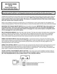
Page #11Breakout Box Circuit DiagnosisThe Telorvek panel can be used as a BREAKOUT BOX for testing circuits running to and from theEEC Processor. Listed below is the Ford circuit number, circuit description, E.E.C processor pinnumber, Telorvek panel number the circuit runs to, Ford wire color and the color of wire we used.Following the diagnostic procedures that can be found in the ENGINE / EMISSIONS DIAGNOSISSHOP MANUAL that can be purchased at your local Ford dealer all trouble codes can bediagnosed.NOTE: Not all of the terminals on this panel will be used in your application. Your kit wassupplied with the correct wiring based on the engine year and size. The following chart will list thesame items/sensors but on different panel terminals. This is due to three different engine sizes areconnected to this panel. Follow the <strong>installation</strong> <strong>instructions</strong> and the printing on the wires carefullywhen connecting wires to this panel.Circuit Description EEC pin# Panel # Ford Color TDZ Color361 Ign, Air By-Pass/Canister Purge Sol 5 Red Red361 Ign, EGR Sol/Air Divert Sol 6 Red Red361 Ign, Injectors 7 Red Red361 Ign, ISC, MAF (*) 37,57 8 Red Red16 Ign, Distributor 9 Red Red361 Ign, Positive Coil,ICM 10 Red Red298 Ign, O2 Sensor, (2 Wires CA Emissions) 11 Pink/Orange Orange11 ICM, NEG Coil 12 Tan/Yellow Purple11 Tach 13 Tan/Yellow Purple14354 ECT 7 15 Lt Green/Red Lt Green743 IAT 25 16 Gray Yellow264 ISC 21 17 White/Lt Blue White382 ICM 4 18 Yellow/Black Purple929 ICM 36 19 Pink/Lt Blue Pink395 ICM, Distributor 56 20 Gray/Orange Gray259 Distributor 16 21 Orange/Red Orange74 O2 Sensor 44 22 Gray/Lt Blue Lt Blue310 Knock Sensor (5.0 ONLY) 23 23 Yellow/Red Yellow24570 GRND, Dist, ICM 25 Black/White Black48 GRND, ICM,Dist Shield 20,40 26 Black/White, Black Solid & Black969 GRND, MAF, O2 Sensor 6,60 27 Black Black57 GRND, VSS, O2 Sensor 28 Black Black29->35 not used351 EGRVP, TPS 26 36 Brown/White Brown351 MAP Sensor 37 Brown/White Brown355 TPS 47 38 Gray/White White352 EGRVP 27 39 Brown/Lt Green Lt Green358 MAP (*) 45 40 Lt Green/Black Black926 VIP 1, FP Relay 22 41 Lt Blue/Orange Lt Blue914 VIP 1 (*) 18 42 Tan/Orange Tan915 VIP 1 19 43 Pink/Lt Blue Pink658 VIP 1, SES LT 17 44 Pink/Lt Green Lt Green209 VIP 2 48 45 White/Pink White968 MAF or VIP 9 46 Tan/Lt Blue Tan967 MAF 50 47 Lt Blue/Red Lt Blue914 VIP (man trans) 28 48 Tan/Orange Tan360 EGR Solenoid 33 49 Brown/Pink Brown200 Air Divert Solenoid 34 50 Brown Brown190 Air Bypass or Can Purge 31 51 White/Orange White101 Air Bypass or Can Purge 11 52 Gray/Yellow Gray53->63 not used(*) Does not apply to all applications
Circuit Description EEC pin# Panel # Ford Color TDZ Color361 FP Relay IGN 64 Red Red361 IGN, S.E.S LT 65 Red/Yellow Red361 IGN, TCIL, TCS 66 Red Red361 IGN, Trans 67 White/Red Red361 IGN, Trans 68 Red Red37 Battery 1 69 Yellow Yellow923 Trans 49 70 Orange/Black Orange924 Trans 55 71 Brown/Orange Brown315 Trans 52 72 Pink/Orange Pink480 Trans 53 73 Pink/Yellow Yellow237 Trans, Air Bypass (*) 51 74 Orange/Yellow Orange925 Trans 38 75 White/Yellow White199 MLPS 30 76 Lt Blue/Yellow Yellow511 Brake Input 2 77 Lt Green Purple911 TCIL 32 78 White/Lt Green White224 TCS 41 79 Tan/White Tan679 VSS 3 80 Gray/Black Gray238 FP Relay, Inertia SW 8 81 Dk Green/Yellow Tan198 AC Pressure SW 10 82 Dk Green/Orange --348 O2 Sensor (*) 43 83 Pink --970 Output Shaft VSS 5 84 Dk Green/White Dk Green784 Trans Fluid Temp,4 X 4 Ind 42 85 Lt Blue/Black Orange86->91 not used923 O2 Sensor 49 92 Orange/Black Orange359 Knock Sensor 93 Gray/Red Gray359 IAT, ECT 46 94 Gray/Red Gray359 O2, MAP Sensor 95 Gray/Red Gray359 TPS, EGRVP 96 Gray/Red Gray359 VIP 1, MLP 97 Gray/Red Gray359 Trans 8 98 Gray/Red Gray766 O2 Sensor(*) 29 99 Black/Lt Green Lt Blue555 Injector 58 100 Tan Tan556 Injector 59 101 White White557 Injector 39 102 Brown/Yellow Brown558 Injector 35 103 Brown/Lt Blue Lt Blue559 Injector 15 104 Tan/Black Black560 Injector 12 105 Lt Green/Orange Lt Green561 Injector 13 106 Tan/Red Purple562 Injector 14 107 Lt Blue Dk Blue109->120 not usedPage #12
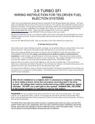
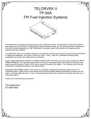
Page #13Fuse Designation & SizeThe harness has a total of eight fuses. Shown below is a diagram of what each fuse protects. Theillustration is the front view of the Telorvek panel.Fuse Block #1 Fuse Block #2I SC,MAF,DI GNE i sCMtrib ITutor,Co IONi l, ICM,2 0AMPF uelPumpReB ATTERYl a y,ECM2 0AMPI I n GNj e ctors ITION1 5AMPT ransmI GNITi s IONi o n1 0AMPE GR ,A ir I D GNi v ertSo ITIONl e noi d s1 0AMPF uelPumpReL țTCI GNlIL,TCSa y( ITIONI GN), S .E.S2 0AMPS o l e noA i r By-PasșC anI GNITIONi d s i s terPurge1 0AMPO xygenSensor I GNITION1 0AMPD esF usei g natio nB Fl useSo ck#1i z eD esF usei g natio nF useSB l o ck#2i z eCopyright InfringementThe Detail Zone has taken the extra effort to produce a quality, easy tounderstand <strong>instructions</strong>. We will aggressively prosecute any other harnesssupplier who attempts to copy this material!!COPYRIGHT © 1995 The Detail Zone