product installation instructions - Ron Francis Wiring
product installation instructions - Ron Francis Wiring
product installation instructions - Ron Francis Wiring

Create successful ePaper yourself
Turn your PDF publications into a flip-book with our unique Google optimized e-Paper software.
Page #6Bag #57 CENTRAL CONTROL MODULE: The Central Control Module (CCM)communicates through the serial data link with the Electronic Control Module (ECM). Thiscommunication allows a scan tool to be connected to the ALDL connector so any troubleshooting can be done. By installing the CCM you will also be able to use all factory GeneralMotors parts. The CCM performs many functions however only a few can be utilized on astreet rod application.Battery & Ignition Connections to the CCM: Plug in the Lt Green connector into theCCM. Uncoil the wires and run the Yellow wire (F1->BATTERY) to a 12 volt (Hot All The Time)source. Run the Orange wire (E5->IGNITION) to a ignition source that is hot (12 Volts) with thekey on and in the crank position. Run the Red wire (E4->ACC IGNITION) to the accessory sideof the ignition switch. This wire must be hot (12 Volts) with the key in the run position but turnoff in the crank position.Ground, Serial Data: Run the Black wire (E16->GROUND) to ground. Run the Tan Wire(E13->49) to terminal #49 on the Telorvek panel. This wire allows the CCM to communicatewith the ECM.Install the black connector into the CCM. Run the Black wire (C1->GROUND) to ground. Runthe Yellow wire (D6->ALDL G) to the ALDL connector and install it in terminal (G) using theterminal provided. Extra care should be taken in making sure this wire is installed in the rightslot.VEHICLE SPEED SENSOR (VSS): A VSS signal input is needed on all General Motors TPIengines. If the ECM does not see that input a CODE 24 WILL SET. The VSS input helpscontrol some of the EGR and IAC functions. You need to provide this input and prevent thiscode one of two ways.Using a 700 R4 TransmissionThe first is most 700 R4 transmissions have the factory pulse generator located in them. Thiscan be connected into the computer to provide this signal. For the 700 R4 transmission that hasa speedometer cable connector we have developed a pulse generator (part #PG6A) thatinstalls in line on the cable to provide the speed signal into the computer. This transmission alsorequires a torque converter lock-up signal which is given by the ECM from the input it receivesfrom the pulse generator. The Detail Zone’s transmission wiring kits includes the wiring for theTCC lock-up and the correct connectors to plug into the factory pulse generator to make thisconnection easy.Other TransmissionsA speed signal into the computer can done simply by purchasing the PG-6A pulse generator. Itinstalls into the speedometer cable and following the <strong>instructions</strong> will wire into the harness.
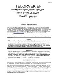
Page #7FINISHING UPConnect the large prewired Orange wire to the ignition circuit of your ignition switch. This is anignition feed that is controlled by the ignition switch. This is not an accessory feed and mustremain hot even when the engine is cranking.Connect the large prewired Yellow battery feed wire to a battery feed. This is a battery feedthat must remain hot even with the key off. Make sure this is a good connection. If you have aMaster Disconnect switch, install this wire on the battery side of the switch so it will remain hotwith the Disconnect off.The Black ground wire from the TELORVEK III Panel runs direct to the battery. Do notconsider grounding the battery to the frame and then the engine to the frame. Run the batteryground directly to the engine.STARTING THE ENGINEYou have now made all of the connections necessary to TRY to start your car. If you try now,you will be disappointed since you did not hook up the battery. You can do so now. If you turnthe key on but do not crank engine, you will hear the fuel pump for about 2 to 4 seconds beforeit stops. This will indicate the pump is ready. During normal operating it is best if you do notwait till the pump stops as this is not an indication that the pressure is up. There is no need to"pump" the throttle on fuel injected cars.TROUBLE CODES:Connecting a jumper wire from terminal A to terminal B of the ALDL connector (white and blackwires) will allow the computer to "flash" trouble codes in the "CODES" light mounted on theTELORVEK III panel or dash board. Each code will flash 3 times. Each number is flashedseparate. Example: Thirteen is flashed as a single flash followed by three flashes. This willrepeat three times before moving on to any addition codes. Since the engine must be stoppedfor this test, code 12 will always flash first.12 Distributor not operating (turning)13 Left Oxygen Sensor Circuit14 Coolant Temperature Sensor (High Temp.Indicated)15 Coolant Temperature Sensor (Low Temp.Indicated)16 Opti-Spark Ignition (Low Resolution Pulse)21 Throttle Position Sensor (Signal Voltage High)22 Throttle Position Sensor (Signal Voltage Low)23 Intake Air Temperature Sensor (Low Temp.Indicated)24 Vehicle Speed Sensor25 Intake Air Temperature Sensor (High Temp.Indicated)26 Quad-Driver Module (#1 Circuit)27 Quad-Driver Module (#2 Circuit)28 Quad-Driver Module (#3 Circuit)32 Exhaust Gas Recirculation Circuit33 Map Absolute Pressure (High Voltage LowVacuum)34 Map Absolute Pressure (Low Voltage HighVacuum)36 Opti-spark Ignition (Faulty High Resolution OrExtra Low Pulse Detected)41 Electronic Spark Timing (Open Or Shorted)42 Electronic Spark Timing (Grounded Circuit)43 Electronic Spark Control (Knock Sensors)44 Left Oxygen Sensor (Lean)45 Left Oxygen Sensor (Rich)51 MEM-CAL (Replace Prom)52 Engine Oil Temperature (Low Temp. Indicated)53 System Over-voltage (Check Alternator)55 Fuel Lean Monitor62 Engine Oil Temperature Circuit (High Temp.Indicated)63 Right Oxygen Sensor Circuit (Open Circuit)64 Right Oxygen Sensor Circuit (Lean)65 Right Oxygen Sensor Circuit (Rich)
Page #9General Motors EFI Connections1) (NOT USED)2) (NOT USED)3) Coil Driver Connector13) Coolant TemperatureSensor14) Canister PurgeSolenoid4) (NOT USED)5) EGR Solenoid6) ALDL Connector15) Male DistributorTest Connector16) Female DistributorTest Connector7) Oxygen Sensor8) Injectors9) Knock Sensor17) Oil SwitchConnector18) Throttle Position Sensor/ Engine Oil Temp Sensor10) Manifold Air PressureSensor19) Fuel Pump, Fan, Park/NeutralRelay11) Idle Air Control20) Intake Air Temp Sensor12) Air Divert Solenoid151617181920