RCBO - Lutron Lighting Installation Specialists
RCBO - Lutron Lighting Installation Specialists
RCBO - Lutron Lighting Installation Specialists

Create successful ePaper yourself
Turn your PDF publications into a flip-book with our unique Google optimized e-Paper software.
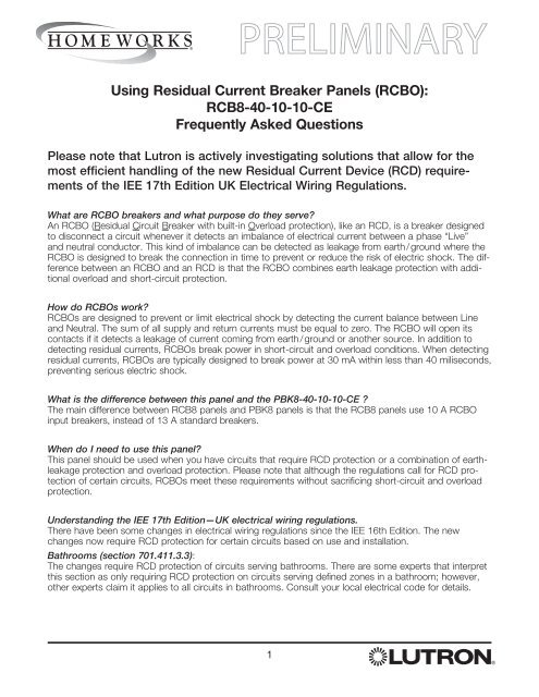
Using Residual Current Breaker Panels (<strong>RCBO</strong>):<br />
RCB8-40-10-10-CE<br />
Frequently Asked Questions<br />
Please note that <strong>Lutron</strong> is actively investigating solutions that allow for the<br />
most efficient handling of the new Residual Current Device (RCD) requirements<br />
of the IEE 17th Edition UK Electrical Wiring Regulations.<br />
What are <strong>RCBO</strong> breakers and what purpose do they serve<br />
An <strong>RCBO</strong> (Residual Circuit Breaker with built-in Overload protection), like an RCD, is a breaker designed<br />
to disconnect a circuit whenever it detects an imbalance of electrical current between a phase “Live”<br />
and neutral conductor. This kind of imbalance can be detected as leakage from earth / ground where the<br />
<strong>RCBO</strong> is designed to break the connection in time to prevent or reduce the risk of electric shock. The difference<br />
between an <strong>RCBO</strong> and an RCD is that the <strong>RCBO</strong> combines earth leakage protection with additional<br />
overload and short-circuit protection.<br />
How do <strong>RCBO</strong>s work<br />
<strong>RCBO</strong>s are designed to prevent or limit electrical shock by detecting the current balance between Line<br />
and Neutral. The sum of all supply and return currents must be equal to zero. The <strong>RCBO</strong> will open its<br />
contacts if it detects a leakage of current coming from earth / ground or another source. In addition to<br />
detecting residual currents, <strong>RCBO</strong>s break power in short-circuit and overload conditions. When detecting<br />
residual currents, <strong>RCBO</strong>s are typically designed to break power at 30 mA within less than 40 miliseconds,<br />
preventing serious electric shock.<br />
What is the difference between this panel and the PBK8-40-10-10-CE <br />
The main difference between RCB8 panels and PBK8 panels is that the RCB8 panels use 10 A <strong>RCBO</strong><br />
input breakers, instead of 13 A standard breakers.<br />
When do I need to use this panel<br />
This panel should be used when you have circuits that require RCD protection or a combination of earthleakage<br />
protection and overload protection. Please note that although the regulations call for RCD protection<br />
of certain circuits, <strong>RCBO</strong>s meet these requirements without sacrificing short-circuit and overload<br />
protection.<br />
Understanding the IEE 17th Edition—UK electrical wiring regulations.<br />
There have been some changes in electrical wiring regulations since the IEE 16th Edition. The new<br />
changes now require RCD protection for certain circuits based on use and installation.<br />
Bathrooms (section 701.411.3.3):<br />
The changes require RCD protection of circuits serving bathrooms. There are some experts that interpret<br />
this section as only requiring RCD protection on circuits serving defined zones in a bathroom; however,<br />
other experts claim it applies to all circuits in bathrooms. Consult your local electrical code for details.<br />
1
General circuits (section 411.3.3):<br />
The changes require RCD protection on all circuits serving socket-outlets rated up to 20A intended for<br />
general-use and mobile equipment rated up to 32A for outdoor use.<br />
Other circuits (sections 522.6.6, 522.6.7, and 522.6.8):<br />
Changes have been made regarding how cable must be protected, adding RCD protection in particular<br />
installations.<br />
Four basic ways to provide protection of circuit cabling as described in the regulations:<br />
1. Installing cable at least 50 mm deep.<br />
2. Mechanical protection (conduit or the like).<br />
3. Special routing of cables within specifically defined zones - so called “safe zones”.<br />
4. RCD protection (new).<br />
Two characteristics of installations determine which protection method(s) are acceptable:<br />
1. Supervised or unsupervised.<br />
2. Metallic parts in the walls.<br />
Here is how these interplay:<br />
A. When installed at least 50 mm deep, and the walls do not contain metallic parts, the cables in supervised<br />
or unsupervised installations require no further protection (No RCD’s, no mechanical protection,<br />
no special cable routing).<br />
B. When installed at least 50 mm deep, and the walls contain metallic parts, the cables in unsupervised<br />
installations must be mechanically protected or RCD protected.<br />
C. When installed
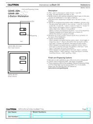
<strong>Installation</strong> Instructions<br />
Please Read Before Installing<br />
Residual Current<br />
Breaker Panel<br />
RCB8-40-10-10-CE<br />
220‐240 V 50 Hz 40 A<br />
Important Notes<br />
Codes: All wiring must be installed in accordance with all<br />
local and national electrical codes.<br />
Cooling: This equipment is air-cooled. Mount in a place<br />
where the vented cover will not be blocked. Clearance of<br />
30 cm (12 in) is required in front of the unit.<br />
Environment: This unit is intended for indoor use only.<br />
Mounting Location: Modules will hum slightly and internal<br />
relays will click while in use. Mount in a location where such<br />
noise is acceptable.<br />
Mount panel so that mains voltage wiring will be at least<br />
1,8 m (6 ft) from audio or electronic equipment and its<br />
wiring.<br />
<strong>Installation</strong><br />
1. Mount Rough-In Enclosure using one of the following<br />
methods (mounting hardware is not provided):<br />
a. Surface Mount—Use keyholes shown in Figure 2 with<br />
bolts sufficient for 45 kg (100 lbs) load (M6 (1/4 in)<br />
bolts recommended).<br />
b. Recess Mount—Use screws sufficient for 45 kg<br />
(100 lbs) through the corners of the panel. Mount<br />
panel flush to or not more than 3 mm (1/8 in) below the<br />
finished wall surface. Enclosure is 9,8 cm (3 7 ⁄8 in) deep<br />
past cover mounting holes. Enclosure cover dimensions<br />
are 161 cm x 47 cm (63 3 ⁄8 in x 18 1 ⁄2 in).<br />
WARNING: Locate and lock supply breakers (MCB)<br />
in the OFF position before wiring to power terminal<br />
blocks. Wiring with the power ON can result in serious<br />
personal injury or death.<br />
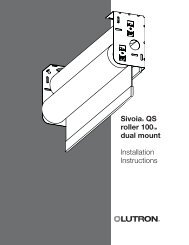
2. Run power wiring (220-240 V ) into the panel. Locations<br />
to run power wiring into the panel are shown at right<br />
(Figure 3). The main circuit breaker (MCB) is a 4 pole, 3<br />
phase and will accept wire up to 35 mm 2 (2 AWG) as<br />
shown in Figure 1 below. Tighten circuit breaker (MCB) to<br />
3 N•m (2,2 in-lbs). Do not overtighten.<br />
Figure 1—Power Wiring<br />
Main Circuit Breaker (MCB)<br />
Figure 2—Panel Dimensions<br />
5,4 (2,1)<br />
113 (44,5)<br />
41,6 (16,4)<br />
33<br />
(13,0)<br />
33<br />
(13,0)<br />
42,7<br />
(16,8)<br />
45,7<br />
(18,0)<br />
Preferred Power Wiring Entry<br />
Recess Mount with 4 Screws<br />
Surface Mount with Keyholes<br />
Module Locations (8 max.)<br />
Terminal Blocks<br />
Output Breakers<br />
Input Breakers<br />
4-pole, 3 Phase<br />
Main Circuit Breaker (MCB)<br />
160 (63,0)<br />
diameter:<br />
8 mm<br />
(0,31 in)<br />
diameter:<br />
16 mm<br />
(0,63 in)<br />
UP<br />
Mount Panel<br />
Vertically<br />
Figure 3—Wire Entry and Panel Mounting<br />
Phase 1<br />
Phase 2<br />
Phase 3<br />
Neutral<br />
Torque breakers to 3,0 N•m (2,2 in-lbs)<br />
Alternate Power Wiring Entry<br />
Control Wiring Entry (IEC PELV)
3. Install load wiring. Dress the wire to the left side of the<br />
terminal blocks (modules will be to the right of the terminal<br />
blocks as shown in Figure 3). Terminal blocks will<br />
accept one 4,0 mm 2 (12 AWG) wire or two 1,0 mm 2 to<br />
1,5 mm 2 (18 AWG to 16 AWG) wires. Tighten terminal<br />
blocks to 0,40 to 0,57 N•m (3,5 to 5,0 in-lbs). Do not<br />
overtighten.<br />
Each module controls up to 4 loads. Wiring for the HW-<br />
RPM-4A / 4U-LL-230 modules is shown in Figure 5.<br />
Label each wire clearly as you wire to the terminal blocks.<br />
NOTE: The total combined load of all four circuits in an<br />
HW-RPM-4A / 4U-LL-230 module must be 10 A<br />
(2 300 VA) or less. No individual output of the HW-RPM-<br />
4A / 4U-LL-230 module may exceed 10 A (2 300 VA).<br />
Exceeding these maximums can damage the module.<br />
4. Test all load wiring. Turn on input power to the module<br />
locations using the module circuit breakers (shown in<br />
Figure 3). The pre-installed bypass jumpers will distribute<br />
power to each load and MUST NOT be removed until after<br />
all loads are fully tested and all modules are installed.<br />
Check all connected lighting to ensure it is on. If a circuit<br />
breaker trips, a wiring error exists and must be resolved.<br />
Note: Do not remove bypass jumpers at this time. They<br />
will be removed after the modules are installed.<br />
5. Install cover. Ensure vents are on the right hand side of<br />
the cover, over the module area. Tighten cover screws<br />
to 2,3 N•m (20 in-lbs). If a processor or module interface<br />
has not been installed, leave this instruction sheet in the<br />
enclosure.<br />
Figure 5—Module Wiring (HW-RPM-4A-LL-230<br />
and HW-RPM-4U-LL-230 only)<br />
Output 1<br />
Output 2<br />
Output 3<br />
Output 4<br />
(Module 1 of 8 shown)<br />
Red 1<br />
Red 2<br />
Red 3<br />
Red 4<br />
Brown<br />
Blue<br />
Torque terminal blocks from<br />
0,4 to 0,57 N•m (3,5 in-lbs to 5 in-lbs)<br />
Torque circuit breakers 3 N•m (2,2 in-lbs)<br />
Figure 4—Load Wiring<br />
Bypass Jumper<br />
(do not remove until<br />
after the modules are installed)<br />
Output 1<br />
Output 2<br />
Load<br />
Output 3<br />
Output 4<br />
(Module 1 of 8 shown)<br />
Load Neutral 1<br />
Load Neutral 2<br />
Load Neutral 3<br />
Load Neutral 4<br />
Blue<br />
<strong>Lutron</strong> Electronics Co., Inc.<br />
7200 Suter Road<br />
Coopersburg, PA 18036<br />
USA<br />
<strong>Lutron</strong> EA Ltd.<br />
6 Sovereign Close<br />
Wapping, London E1W 3JF, UK<br />
Made and printed in the U.S.A. 9 / 08 P/N 043-XXX Rev. A<br />
Torque terminal blocks from<br />
0,4 to 0,57 N•m (3,5 in-lbs to 5 in-lbs)<br />
<strong>Lutron</strong> GL Ltd.<br />
15 Hoe Chiang Road<br />
#07-03<br />
Singapore 089316<br />
4<br />
Warranty: For Warranty information, please see the Warranty enclosed with the product, or visit www.lutron.com/resiinfo.<br />
This product may be covered under one or more of the following U.S. patents: 4,797,599; 4,889,999; 5,170,068; 5,237,207 and corresponding<br />
foreign patents. U.S. and foreign patents pending. <strong>Lutron</strong>, HomeWorks and the sunburst logo are registered trademarks and the HomeWorks logo<br />
is a trademark of <strong>Lutron</strong> Electronics Co., Inc.<br />
©2008 <strong>Lutron</strong> Electronics Co., Inc.