SwRI engineers design, build and test a prototype wind turbine array
SwRI engineers design, build and test a prototype wind turbine array
SwRI engineers design, build and test a prototype wind turbine array

Create successful ePaper yourself
Turn your PDF publications into a flip-book with our unique Google optimized e-Paper software.
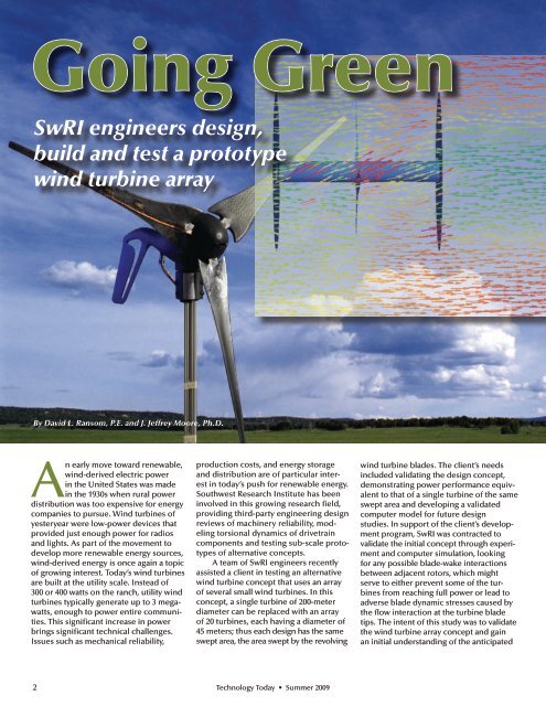
Going Green<br />
<strong>SwRI</strong> <strong>engineers</strong> <strong>design</strong>,<br />
<strong>build</strong> <strong>and</strong> <strong>test</strong> a <strong>prototype</strong><br />
<strong>wind</strong> <strong>turbine</strong> <strong>array</strong><br />
By David L. Ransom, P.E. <strong>and</strong> J. Jeffrey Moore, Ph.D.<br />
An early move toward renewable,<br />
<strong>wind</strong>-derived electric power<br />
in the United States was made<br />
in the 1930s when rural power<br />
distribution was too expensive for energy<br />
companies to pursue. Wind <strong>turbine</strong>s of<br />
yesteryear were low-power devices that<br />
provided just enough power for radios<br />
<strong>and</strong> lights. As part of the movement to<br />
develop more renewable energy sources,<br />
<strong>wind</strong>-derived energy is once again a topic<br />
of growing interest. Today’s <strong>wind</strong> <strong>turbine</strong>s<br />
are built at the utility scale. Instead of<br />
300 or 400 watts on the ranch, utility <strong>wind</strong><br />
<strong>turbine</strong>s typically generate up to 3 megawatts,<br />
enough to power entire communities.<br />
This significant increase in power<br />
brings significant technical challenges.<br />
Issues such as mechanical reliability,<br />
production costs, <strong>and</strong> energy storage<br />
<strong>and</strong> distribution are of particular interest<br />
in today’s push for renewable energy.<br />
Southwest Research Institute has been<br />
involved in this growing research field,<br />
providing third-party engineering <strong>design</strong><br />
reviews of machinery reliability, modeling<br />
torsional dynamics of drivetrain<br />
components <strong>and</strong> <strong>test</strong>ing sub-scale <strong>prototype</strong>s<br />
of alternative concepts.<br />
A team of <strong>SwRI</strong> <strong>engineers</strong> recently<br />
assisted a client in <strong>test</strong>ing an alternative<br />
<strong>wind</strong> <strong>turbine</strong> concept that uses an <strong>array</strong><br />
of several small <strong>wind</strong> <strong>turbine</strong>s. In this<br />
concept, a single <strong>turbine</strong> of 200-meter<br />
diameter can be replaced with an <strong>array</strong><br />
of 20 <strong>turbine</strong>s, each having a diameter of<br />
45 meters; thus each <strong>design</strong> has the same<br />
swept area, the area swept by the revolving<br />
<strong>wind</strong> <strong>turbine</strong> blades. The client’s needs<br />
included validating the <strong>design</strong> concept,<br />
demonstrating power performance equivalent<br />
to that of a single <strong>turbine</strong> of the same<br />
swept area <strong>and</strong> developing a validated<br />
computer model for future <strong>design</strong><br />
studies. In support of the client’s development<br />
program, <strong>SwRI</strong> was contracted to<br />
validate the initial concept through experiment<br />
<strong>and</strong> computer simulation, looking<br />
for any possible blade-wake interactions<br />
between adjacent rotors, which might<br />
serve to either prevent some of the <strong>turbine</strong>s<br />
from reaching full power or lead to<br />
adverse blade dynamic stresses caused by<br />
the flow interaction at the <strong>turbine</strong> blade<br />
tips. The intent of this study was to validate<br />
the <strong>wind</strong> <strong>turbine</strong> <strong>array</strong> concept <strong>and</strong> gain<br />
an initial underst<strong>and</strong>ing of the anticipated<br />
2<br />
Technology Today • Summer 2009
D016925-2097<br />
David L. Ransom, P.E., (left) is a principal<br />
engineer in <strong>SwRI</strong>’s Fluids Engineering<br />
Department in the Mechanical <strong>and</strong> Materials<br />
Engineering Division. Ransom specializes in<br />
rotordynamics <strong>and</strong> structural dynamics for both<br />
energy <strong>and</strong> space exploration applications.<br />
Dr. J. Jeffrey Moore is a program manager in<br />
the Fluids Engineering Department. Moore’s<br />
areas of expertise include turbomachinery<br />
rotordynamics <strong>and</strong> fluid dynamics research for<br />
the natural gas, power generation <strong>and</strong> <strong>wind</strong><br />
power industries.<br />
D017017<br />
<strong>design</strong> challenges for a full-scale <strong>array</strong>.<br />
The <strong>SwRI</strong> team proposed to arrange<br />
multiple commercially available <strong>wind</strong><br />
<strong>turbine</strong>s in an <strong>array</strong> pattern <strong>and</strong> perform<br />
<strong>test</strong>s to evaluate the <strong>design</strong> for<br />
performance as well as mechanical<br />
integrity. <strong>SwRI</strong> researchers also used<br />
computational fluid dynamics to study<br />
the possible blade-wake or tip-vortex<br />
interactions between adjacent rotors.<br />
Wind tunnel <strong>test</strong>ing<br />
As a result of the initial evaluation,<br />
the <strong>SwRI</strong> team <strong>design</strong>ed, built <strong>and</strong> <strong>test</strong>ed<br />
a <strong>turbine</strong> <strong>array</strong> <strong>prototype</strong> to verify key<br />
performance characteristics <strong>and</strong> to support<br />
future <strong>design</strong> work<br />
on larger <strong>turbine</strong> <strong>array</strong>s.<br />
The <strong>array</strong> consisted of<br />
seven 400-watt, commercially<br />
available <strong>wind</strong><br />
<strong>turbine</strong>s constructed on<br />
a 25-foot-tall platform.<br />
The center <strong>turbine</strong> of the<br />
<strong>array</strong> was erected at a<br />
height of 15 feet to meet<br />
the centerline of the<br />
<strong>wind</strong> tunnel at NASA’s<br />
Langley Research Center<br />
in Hampton, Va. The<br />
Langley Full Scale Tunnel<br />
(LFST) is a National Historical<br />
L<strong>and</strong>mark significant<br />
to the advancement<br />
of aeronautical research<br />
dating from 1931 <strong>and</strong><br />
continuing today through model <strong>test</strong>s<br />
of all current front-line U.S. jet fighter<br />
aircraft. The tunnel is 50 feet in length, 60<br />
feet wide <strong>and</strong> 30 feet high.<br />
Performance <strong>test</strong> results<br />
Researchers added instrumentation<br />
to each <strong>turbine</strong> in <strong>SwRI</strong>’s seven-rotor <strong>array</strong><br />
to provide data on center <strong>turbine</strong> power,<br />
blade strain <strong>and</strong> <strong>turbine</strong> speed. Several<br />
flow visualization features were included<br />
in the experimental rig to better underst<strong>and</strong><br />
potential <strong>turbine</strong> interactions.<br />
The seven-rotor <strong>array</strong> was <strong>test</strong>ed in<br />
a variety of conditions, including varying<br />
the number of active <strong>turbine</strong>s, spacing<br />
between active <strong>turbine</strong>s, <strong>wind</strong> speed <strong>and</strong><br />
The <strong>wind</strong> <strong>turbine</strong> <strong>array</strong> was evaluated in the Langley Full Scale Tunnel,<br />
at NASA Langley Research Center, Hampton, Va. The center <strong>turbine</strong> is<br />
15 feet from the tunnel floor. The <strong>wind</strong> tunnel is 30 feet high.<br />
D017014<br />
Technology Today • Summer 2009 3
D017028<br />
Spacing study results for 9 meters per second <strong>wind</strong><br />
speed indicate no measurable difference in power<br />
performance of the middle <strong>turbine</strong> over the full range of<br />
spacing conditions.<br />
<strong>array</strong> yaw relative to <strong>wind</strong> direction. The<br />
results of all conditions were compared<br />
to the baseline performance results of a<br />
single <strong>turbine</strong>. The repeatability of the<br />
results was found to be around 4 percent.<br />
This demonstrates that even across a<br />
wide range of <strong>test</strong> article configurations,<br />
the maximum possible impact to <strong>turbine</strong><br />
performance is less than 4 percent, suggesting<br />
that performance from operation<br />
in an <strong>array</strong> configuration does not significantly<br />
affect performance.<br />
The <strong>SwRI</strong> team conducted a study in<br />
which the outer six <strong>turbine</strong>s were initially<br />
spaced at 2 percent of the diameter relative<br />
to the center <strong>turbine</strong>. Spacing was<br />
then incrementally increased to a maximum<br />
of 16 percent. Spacing study results<br />
indicated that the influence of the neighboring<br />
rotors in the full seven-rotor <strong>array</strong><br />
was not detectable within the repeatability<br />
of the <strong>test</strong> results. This indicated that<br />
any possible effects of rotor interaction<br />
on <strong>array</strong> performance were limited to less<br />
than 4 percent when compared to singlerotor<br />
performance. Tests run in the yaw<br />
condition did show a distinct drop in performance<br />
as expected, but the spacing<br />
influence in yaw was still negligible.<br />
Flow visualization<br />
Using a<br />
smoke rake integrated<br />
with the<br />
LFST traversing<br />
mechanism, <strong>SwRI</strong><br />
<strong>engineers</strong> injected<br />
smoke streams<br />
into the flow for<br />
overall streamline<br />
visualization. Initial<br />
results showed<br />
periodic fluctuations in the smoke streams<br />
corresponding to the vortex shedding frequency<br />
of the primary rake structure. This<br />
is an unsteady flow phenomenon in<br />
which vortices form behind an obstruction<br />
in the flow (the rake structure)<br />
<strong>and</strong> periodically detach, creating disturbances<br />
in the smoke flow. Because<br />
of this, additional smoke <strong>test</strong>ing was<br />
performed by rotating the rake so that<br />
the outflow ports of the tines were not<br />
directly downstream of this wake.<br />
The team attempted several variations<br />
in the smoke rake arrangements,<br />
such as spacing <strong>and</strong> restricting the number<br />
of tubes to obtain clearer images,<br />
but inherent turbulence in the flow<br />
made it difficult to generate a clear<br />
image of the flow field surrounding the<br />
A smoke generator <strong>and</strong> smoke rake were<br />
installed in the Langley Full Scale Tunnel.<br />
The traversing mechanism permitted remote<br />
control of rake location to help visualize flow<br />
at different locations on the <strong>array</strong>.<br />
D016580<br />
4<br />
Technology Today • Summer 2009
D017011<br />
Smoke streams illustrate periodic vortex shedding<br />
from the smoke rake wake on the smoke<br />
streams. The influence of vortex shedding is<br />
minimized by rotating the rake.<br />
<strong>turbine</strong>s. In still images <strong>and</strong> video, no<br />
clear structure of the flow field was evident<br />
because of the <strong>turbine</strong>s. St<strong>and</strong>ard<br />
<strong>and</strong> slow-motion video with stroboscopic<br />
illumination synchronized to the<br />
rotation of the center <strong>turbine</strong> showed<br />
the flow field passing through the <strong>turbine</strong><br />
planes with no apparent effect.<br />
This was evidenced by the fact that the<br />
strobe light could not “freeze” images of<br />
smoke patterns. Instead, the smoke continually<br />
moved in all recorded images.<br />
<strong>SwRI</strong> researchers used a mixture of<br />
titanium dioxide (TiO 2<br />
), kerosene <strong>and</strong><br />
oleic acid to record flow patterns on<br />
the rotating blades. The mixture was<br />
painted onto the front <strong>and</strong> back sides<br />
of one of the center <strong>turbine</strong> blades, <strong>and</strong><br />
the tunnel was subsequently brought<br />
up to operating condition. This allowed<br />
the TiO 2<br />
mixture to travel on the surface<br />
under the aerodynamic forces while the<br />
kerosene evaporated, leaving a trace of<br />
the surface flow patterns.<br />
The <strong>SwRI</strong> team installed a grid<br />
of retro-reflective tufts on the <strong>array</strong><br />
structure downstream of the <strong>turbine</strong><br />
blade plane to<br />
examine flow<br />
structure in the<br />
wake of the <strong>turbine</strong>s.<br />
During<br />
operation, the<br />
tufts reacted to<br />
the local flow<br />
field. Photographs<br />
of the<br />
tuft <strong>array</strong> showed the flow structure at<br />
the tuft grid for the two-rotor case when<br />
the center <strong>and</strong> upper rotors are separated<br />
by 2 percent. Capturing images in<br />
this configuration was difficult because<br />
of the added wake of the photographer<br />
<strong>and</strong> camera when filming from upstream<br />
of the <strong>turbine</strong> <strong>array</strong>. Nonetheless, the<br />
tufts showed some angularity in the wake<br />
of the two active <strong>turbine</strong>s <strong>and</strong> were very<br />
well aligned with the mean flow direction<br />
everywhere else. A more straight-on<br />
view might have shown the dividing line<br />
between the swirled flow at the bottom<br />
of the top <strong>turbine</strong> (swirled flow to the<br />
left) <strong>and</strong> the top of the middle <strong>turbine</strong><br />
(swirled flow to the right).<br />
D017013<br />
Strain gage measurements<br />
Researchers installed strain gages<br />
on a single blade of the <strong>array</strong>’s center<br />
<strong>turbine</strong>. The gages were placed at three<br />
locations: outboard, midboard <strong>and</strong> inboard<br />
from the tip <strong>and</strong> data was transmitted<br />
through a telemetry system. Measured<br />
root mean square (RMS) strain distribution<br />
at the 12 m/sec <strong>wind</strong> speed shows<br />
typical cantilever beam shape with peak<br />
strain at the inboard (IB) location <strong>and</strong><br />
minimum strain at the outboard (OB)<br />
location. This is an indication of the blade<br />
load distribution, which would demonstrate<br />
more variation between various<br />
Technology Today • Summer 2009 5
This photo shows grid tuft visualization for a<br />
two-rotor configuration at 2 percent <strong>turbine</strong><br />
<strong>array</strong> spacing.<br />
D017012<br />
spacing configurations if there was a<br />
real influence on <strong>turbine</strong> performance.<br />
These results show no clear difference<br />
in the RMS strain distribution, even with<br />
closely spaced <strong>turbine</strong>s.<br />
Researchers compared data from<br />
the frequency spectrum of the measured<br />
dynamic strain between the two-rotor<br />
data at 2 percent spacing <strong>and</strong> the full<br />
<strong>array</strong> data at 2 percent spacing, all at 9<br />
meters per second (m/sec) <strong>wind</strong> speed.<br />
The synchronous response was elevated<br />
for the two closely spaced rotor <strong>test</strong>s<br />
compared to the single rotor results. This<br />
indicates some amount of blade wake<br />
interaction, despite the inability to detect<br />
interaction with either performance measurement<br />
or flow visualization.<br />
Computational fluid dynamics (CFD)<br />
simulation<br />
To support future <strong>design</strong> studies,<br />
the research team developed <strong>and</strong> analyzed<br />
a CFD model of the <strong>test</strong> rotor for<br />
D017015<br />
various<br />
<strong>wind</strong> speed<br />
<strong>and</strong> <strong>turbine</strong><br />
spacing conditions.<br />
With a<br />
CFD simulation<br />
that was validated<br />
by experimental data,<br />
<strong>SwRI</strong> <strong>engineers</strong> gained<br />
more insight into the<br />
structure of the flow<br />
through the <strong>turbine</strong> <strong>array</strong>.<br />
Similar to the <strong>wind</strong> tunnel <strong>test</strong>s,<br />
a parametric spacing study was<br />
performed in CFD simulation with<br />
similar results. The CFD-predicted<br />
power performance of the <strong>turbine</strong>s<br />
was not strongly influenced by the<br />
<strong>array</strong> configuration. However, it was<br />
clear that there was some interaction<br />
between neighboring <strong>turbine</strong>s, such as a<br />
reduction in tangential velocity between<br />
two co-rotating <strong>turbine</strong>s.<br />
The center <strong>turbine</strong> blade was instrumented with six strain gages using<br />
a telemetry system to transmit data to the data acquisition system.<br />
The freestream <strong>wind</strong> flowing into<br />
the rotor blade usually generates a wake<br />
that develops downstream of the blade<br />
because of rotation. The wake can be<br />
divided into the central vortex<br />
generated by the hub <strong>and</strong> the<br />
tip vortex developed from<br />
the blade tip. The flow<br />
field results in an<br />
unusually complex<br />
three-dimensional<br />
vortex structure<br />
that was captured accurately<br />
with the<br />
CFD simulation<br />
for an <strong>array</strong> of<br />
two co-rotating<br />
<strong>turbine</strong>s. The interaction<br />
between the vortex structure<br />
produced by two co-rotating <strong>turbine</strong>s is<br />
quantified <strong>and</strong> power performance for the<br />
<strong>turbine</strong> <strong>array</strong> is predicted.<br />
6<br />
Technology Today • Summer 2009
The graph shows measured root mean square (RMS) strain<br />
distribution along the <strong>turbine</strong> blade. Measured<br />
results show no clear difference in RMS strain for varying<br />
<strong>turbine</strong> <strong>array</strong> spacing.<br />
Acknowledgments<br />
The authors would like to acknowledge the contributions<br />
of the other team members who made<br />
this project a success: Program Manager Leigh<br />
Griffith, Staff Scientist Dr. Jerome Helffrich, Research<br />
Engineer Dr. Vishy Iyengar, Research Engineer<br />
Jonathan Moody, Principal Technician Terry<br />
Schiebel, Engineer Melissa Wilcox <strong>and</strong><br />
former <strong>SwRI</strong> staff member Dr. Daniel Scharpf.<br />
D017029<br />
Future studies<br />
Based on the results of<br />
this combined experimental<br />
<strong>and</strong> analytical development<br />
program, <strong>SwRI</strong> researchers<br />
drew several conclusions<br />
regarding the operation of<br />
<strong>wind</strong> <strong>turbine</strong>s in a closely<br />
spaced <strong>array</strong>.<br />
Any possible effects of rotor interaction<br />
on <strong>array</strong> performance were limited<br />
to less than 4 percent when compared to<br />
single-rotor performance. Based on the<br />
single session repeatability, it was more<br />
likely that the influence of adjacent rotors<br />
was less than one percent for nearoptimum<br />
tip speed ratios. Operation in a<br />
yawed orientation did not impact the <strong>array</strong><br />
any more than it did a single rotor. Computational<br />
fluid dynamics tools can be<br />
used to model the multi-rotor concept,<br />
which can be very important in evaluating<br />
future <strong>wind</strong> <strong>turbine</strong> <strong>design</strong>s.<br />
The results of this activity were<br />
encouraging, <strong>and</strong> the experimental program<br />
provided a large amount of data<br />
to support future <strong>wind</strong> <strong>turbine</strong> <strong>array</strong><br />
development work. The performance<br />
data, flow visualization results <strong>and</strong> blade<br />
strain data can all be used to validate<br />
simulation tools as required in future<br />
<strong>design</strong> cycles. The progress made on the<br />
CFD modeling provided the knowledge<br />
necessary to more accurately model<br />
future <strong>design</strong>s with the ability to validate<br />
new ideas <strong>and</strong> techniques against existing<br />
experimental results. The effort<br />
expended in the current phase will continue<br />
to pay dividends as the <strong>wind</strong> <strong>turbine</strong><br />
<strong>array</strong> concept matures <strong>and</strong> reaches<br />
field operation. v<br />
Questions about this article<br />
Contact Ransom at (210) 522-5281 or<br />
david.ransom@swri.org or Moore at<br />
(210) 522-5812 or jeff.moore@swri.org.<br />
Computational fluid dynamic vector plot results demonstrate reduced tangential<br />
velocity at the interface between two <strong>turbine</strong>s. CFD simulation predicts only slight<br />
influence of adjacent <strong>turbine</strong>s on <strong>array</strong> performance.<br />
D017018<br />
Technology Today • Summer 2009 7