IVS 102 Operating Instructions - Armstrong Pumps
IVS 102 Operating Instructions - Armstrong Pumps
IVS 102 Operating Instructions - Armstrong Pumps

You also want an ePaper? Increase the reach of your titles
YUMPU automatically turns print PDFs into web optimized ePapers that Google loves.
<strong>IVS</strong> <strong>102</strong><br />
<strong>Operating</strong> <strong>Instructions</strong>
Contents<br />
<strong>Armstrong</strong> <strong>IVS</strong> <strong>102</strong> High Power <strong>Operating</strong> <strong>Instructions</strong><br />
Contents<br />
1 How to Read these <strong>Operating</strong> <strong>Instructions</strong> 4<br />
1.1.1 Copyright, Limitation of Liability and Revision Rights 4<br />
2 Safety 6<br />
2.1.1 High Voltage Warning 6<br />
2.1.2 Safety <strong>Instructions</strong> 6<br />
2.1.3 General Warning 6<br />
2.1.4 Before Commencing Repair Work 7<br />
2.1.5 Special Conditions 7<br />
2.1.7 Avoid unintended start 8<br />
2.1.8 Safe Stop of the frequency converter 8<br />
2.1.9 IT Mains 8<br />
3 Mechanical Installation 10<br />
3.1 How to Get Started 10<br />
3.2 Pre-installation 11<br />
3.2.1 Planning the Installation Site 11<br />
3.2.2 Receiving the Frequency Converter 11<br />
3.2.3 Transportation and Unpacking 12<br />
3.2.4 Lifting 12<br />
3.2.5 Mechanical Dimensions 15<br />
3.2.6 Rated Power 21<br />
3.3 Mechanical Installation 22<br />
3.3.3 Terminal Locations - Frame size D 24<br />
3.3.4 Terminal Locations - Frame size E 27<br />
3.3.5 Terminal Locations - Frame size F 33<br />
3.3.6 Cooling and Airflow 37<br />
3.4 Field Installation of Options 43<br />
3.4.1 Installation of Duct Cooling Kit in Rittal Enclosures 43<br />
3.4.2 Installation of Top-only Duct Cooling Kit 44<br />
3.4.3 Installation of Top and Bottom Covers for Rittal Enclosures 45<br />
3.4.4 Installation of Top and Bottom Covers 45<br />
3.4.5 Outside Installation/ NEMA 3R Kit for Rittal Enclosures 46<br />
3.4.6 Outside Installation /NEMA 3R Kit of Industrial Enclosures 47<br />
3.4.7 Installation of IP00 to IP20 Kits 47<br />
3.4.8 Installation of IP00s D3, D4, & E2 Cable Clamp Bracket 47<br />
3.4.9 Installation on Pedestal 48<br />
3.4.10 Installation of Mains Shield for Frequency Converters 49<br />
3.4.11 F Frame USB Extension Kit 49<br />
3.4.12 Installation of Input Plate Options 50<br />
MG.12.P2.02 1
Contents<br />
<strong>Armstrong</strong> <strong>IVS</strong> <strong>102</strong> High Power <strong>Operating</strong> <strong>Instructions</strong><br />
3.4.13 Installation of D or E Loadshare Option 50<br />
3.5 Frame size F Panel Options 51<br />
4 Electrical Installation 54<br />
4.1 Electrical Installation 54<br />
4.1.1 Power Connections 54<br />
4.1.12 Mains Connection 70<br />
4.1.14 Fuses 72<br />
4.1.20 Control Cable Routing 77<br />
4.1.22 Electrical Installation, Control Terminals 79<br />
4.2 Connection Examples 80<br />
4.2.1 Start/Stop 80<br />
4.2.2 Pulse Start/Stop 80<br />
4.3 Electrical Installation - additional 81<br />
4.3.1 Electrical Installation, Control Cables 81<br />
4.3.2 Switches S201, S202, and S801 83<br />
4.4 Final Set-up and Test 84<br />
4.5 Additional Connections 86<br />
4.5.1 Mechanical Brake Control 86<br />
4.5.3 Motor Thermal Protection 86<br />
5 How to Operate the Frequency Converter 87<br />
5.1.2 How to Operate Graphical LCP (GLCP)How to operate graphical LCP 87<br />
5.1.6 Tips and Tricks 95<br />
6 How to Programme 98<br />
6.1.2 Quick Menu mode 100<br />
6.1.3 Function Set-ups 106<br />
6.1 Parameter lists 130<br />
6.1.1 Main Menu Structure 130<br />
6.1.2 0-** Operation and Display 131<br />
6.1.3 1-** Load / Motor 132<br />
6.1.4 2-** Brakes 133<br />
6.1.5 3-** Reference / Ramps 133<br />
6.1.6 4-** Limits / Warnings 134<br />
6.1.7 5-** Digital In / Out 135<br />
6.1.8 6-** Analog In / Out 136<br />
6.1.9 8-** Communication and Options 137<br />
6.1.10 9-** Profibus 138<br />
6.1.11 10-** CAN Fieldbus 139<br />
6.1.12 11-** LonWorks 139<br />
2 MG.12.P2.02
Contents<br />
<strong>Armstrong</strong> <strong>IVS</strong> <strong>102</strong> High Power <strong>Operating</strong> <strong>Instructions</strong><br />
6.1.13 13-** Smart Logic Controller 140<br />
6.1.14 14-** Special Functions 141<br />
6.1.15 15-** FC Information 142<br />
6.1.16 16-** Data Readouts 144<br />
6.1.17 18-** Info & Readouts 146<br />
6.1.18 20-** FC Closed Loop 147<br />
6.1.19 21-** Ext. Closed Loop 148<br />
6.1.20 22-** Application Functions 150<br />
6.1.21 23-** Time Based Funtions 151<br />
6.1.22 24-** Application Functions 2 152<br />
6.1.23 25-** Cascade Pack Controller 153<br />
6.1.24 26-** Analog I / O Option MCB 109 154<br />
7 General Specifications 155<br />
8 Warnings and Alarms 168<br />
8.1.1 Alarms and Warnings 168<br />
8.1.2 Fault Messages 172<br />
Index 178<br />
MG.12.P2.02 3
How to Read these <strong>Operating</strong>...<br />
<strong>Armstrong</strong> <strong>IVS</strong> <strong>102</strong> High Power <strong>Operating</strong> <strong>Instructions</strong><br />
1<br />
1 How to Read these <strong>Operating</strong> <strong>Instructions</strong><br />
1.1.1 Copyright, Limitation of Liability and Revision Rights<br />
This publication contains information proprietary to <strong>Armstrong</strong>. By accepting and using this manual the user agrees that the<br />
information contained herein will be used solely for operating equipment from <strong>Armstrong</strong> or equipment from other vendors<br />
provided that such equipment is intended for communication with <strong>Armstrong</strong> equipment over a serial communication link. This<br />
publication is protected under the Copyright laws of Denmark and most other countries.<br />
<strong>Armstrong</strong> does not warrant that a software program produced according to the guidelines provided in this manual will<br />
function properly in every physical, hardware or software environment.<br />
Although <strong>Armstrong</strong> has tested and reviewed the documentation within this manual, <strong>Armstrong</strong> makes no warranty or<br />
representation, neither expressed nor implied, with respect to this documentation, including its quality, performance, or fitness<br />
for a particular purpose.<br />
In no event shall <strong>Armstrong</strong> be liable for direct, indirect, special, incidental, or consequential damages arising out of the use, or<br />
the inability to use information contained in this manual, even if advised of the possibility of such damages. In particular,<br />
<strong>Armstrong</strong> is not responsible for any costs, including but not limited to those incurred as a result of lost profits or revenue, loss<br />
or damage of equipment, loss of computer programs, loss of data, the costs to substitute these, or any claims by third parties.<br />
<strong>Armstrong</strong> reserves the right to revise this publication at any time and to make changes to its contents without prior notice or<br />
any obligation to notify former or present users of such revisions or changes.<br />
1.1.2 Symbols<br />
Symbols used in this manual:<br />
NOTE<br />
Indicates something to be noted by the reader.<br />
CAUTION<br />
Indicates a general warning.<br />
WARNING<br />
Indicates a high-voltage warning.<br />
✮<br />
Indicates default setting<br />
1.1.3 Available Literature for <strong>IVS</strong> <strong>102</strong><br />
- <strong>Operating</strong> <strong>Instructions</strong> MG.12.Ex.yy provide the necessary information for getting the frequency converter up and<br />
running.<br />
- Design Guide MG.12.Rx.yy entails all technical information about the frequency converter and customer design and<br />
applications.<br />
- Programming Guide MG.12.Fx.yy provides information on how to programme and includes complete parameter<br />
descriptions.<br />
x = Revision number<br />
yy = Language code<br />
<strong>Armstrong</strong> technical literature is available in print from your local <strong>Armstrong</strong> Sales Office<br />
4 MG.12.P2.02
How to Read these <strong>Operating</strong>...<br />
<strong>Armstrong</strong> <strong>IVS</strong> <strong>102</strong> High Power <strong>Operating</strong> <strong>Instructions</strong><br />
1.1.4 Abbreviations and Standards<br />
1 1<br />
Abbreviations: Terms: SI-units: I-P units:<br />
a Acceleration m/s 2 ft/s 2<br />
AWG American wire gauge<br />
Auto Tune Automatic Motor Tuning<br />
°C Celsius<br />
I Current A Amp<br />
ILIM Current limit<br />
Joule Energy J = N∙m ft-lb, Btu<br />
°F Fahrenheit<br />
FC Frequency Converter<br />
f Frequency Hz Hz<br />
kHz Kilohertz kHz kHz<br />
LCP Local Control Panel<br />
mA Milliampere<br />
ms Millisecond<br />
min Minute<br />
MCT Motion Control Tool<br />
M-TYPE Motor Type Dependent<br />
Nm Newton Metres in-lbs<br />
IM,N Nominal motor current<br />
fM,N Nominal motor frequency<br />
PM,N Nominal motor power<br />
UM,N Nominal motor voltage<br />
par. Parameter<br />
PELV Protective Extra Low Voltage<br />
Watt Power W Btu/hr, hp<br />
Pascal Pressure Pa = N/m2 psi, psf, ft of water<br />
IINV Rated Inverter Output Current<br />
RPM Revolutions Per Minute<br />
SR Size Related<br />
T Temperature C F<br />
t Time s s,hr<br />
TLIM Torque limit<br />
U Voltage V V<br />
Table 1.1 Abbreviation and standards table.<br />
MG.12.P2.02 5
Safety<br />
<strong>Armstrong</strong> <strong>IVS</strong> <strong>102</strong> High Power <strong>Operating</strong> <strong>Instructions</strong><br />
2<br />
2Safety<br />
2.1.1 High Voltage Warning<br />
WARNING<br />
The voltage of the frequency converter and the MCO 101<br />
option card is dangerous whenever it is connected to mains.<br />
Incorrect installation of the motor or frequency converter<br />
may causedeath, serious injury or damage to the equipment.<br />
Consequently, it is essential to comply with the instructions<br />
in this manual as well as local and national rules and safety<br />
regulations.<br />
2.1.2 Safety <strong>Instructions</strong><br />
WARNING<br />
Prior to using functions directly or indirectly influencing<br />
personal safety (e.g. Safe Stop, Fire Mode or other functions<br />
either forcing the motor to stop or attempting to keep it<br />
functioning) a thorough risk analysis and system test must<br />
be carried through. The system tests must include testing<br />
failure modes regarding the control signalling (analog and<br />
digital signals and serial communication.<br />
NOTE<br />
Before using Fire Mode, contact <strong>Armstrong</strong><br />
• Make sure the frequency converter is properly connected to earth.<br />
• Do not remove mains connections, motor connections or other power connections while the frequency converter is<br />
connected to power.<br />
• Protect users against supply voltage.<br />
• Protect the motor against overloading according to national and local regulations.<br />
• The earth leakage current exceeds 3.5 mA.<br />
• The [OFF] key is not a safety switch. It does not disconnect the frequency converter from mains.<br />
2.1.3 General Warning<br />
WARNING<br />
Warning:<br />
Touching the electrical parts may be fatal - even after the<br />
equipment has been disconnected from mains.<br />
Also make sure that other voltage inputs have been disconnected,<br />
(linkage of DC intermediate circuit), as well as the<br />
motor connection for kinetic back-up.<br />
Before touching any potentially live parts of the frequency<br />
converter, wait at least as follows: Be aware that there may<br />
be high voltage on the DC link even when the Control Card<br />
LEDs are turned off. A red LED is mounted on a circuit board<br />
inside the drive to indicate the DC bus voltage. The red LED<br />
will stay lit until the DC link is 50 Vdc or lower.<br />
Voltage Power size Min. Waiting Time<br />
380 - 480 V 110 - 250 kW 20 minutes<br />
315 - 1000 kW 40 minutes<br />
525 - 690 V 45 - 400 kW 20 minutes<br />
450- 1400 kW 30 minutes<br />
Be aware that there may be high voltage on the DC link even when the LEDs are turned off.<br />
6 MG.12.P2.02
Safety<br />
<strong>Armstrong</strong> <strong>IVS</strong> <strong>102</strong> High Power <strong>Operating</strong> <strong>Instructions</strong><br />
WARNING<br />
Leakage Current<br />
The earth leakage current from the frequency converter<br />
exceeds 3.5 mA. According to IEC 61800-5-1 a reinforced<br />
Protective Earth connection must be ensured by means of: a<br />
min. 10mm2 Cu or 16mm2 Al PE-wire or an addtional PE wire<br />
- with the same cable cross section as the Mains wiring -<br />
must be terminated separately.<br />
Residual Current Device<br />
This product can cause a D.C. current in the protective<br />
conductor. Where a residual current device (RCD) is used for<br />
extra protection, only an RCD of Type B (time delayed) shall<br />
be used on the supply side of this product. See also RCD<br />
Application Note MN.90.GX.02.<br />
Protective earthing of the frequency converter and the use<br />
of RCD's must always follow national and local regulations.<br />
2 2<br />
2.1.4 Before Commencing Repair Work<br />
1. Disconnect the frequency converter from mains<br />
2. Disconnect DC bus terminals 88 and 89<br />
3. Wait at least the time mentioned in section General Warning above<br />
4. Remove motor cable<br />
2.1.5 Special Conditions<br />
Electrical ratings:<br />
The rating indicated on the nameplate of the frequency converter is based on a typical 3-phase mains power supply, within the<br />
specified voltage, current and temperature range, which is expected to be used in most applications.<br />
The frequency converters also support other special applications, which affect the electrical ratings of the frequency converter.<br />
Special conditions which affect the electrical ratings might be:<br />
• Single phase applications<br />
• High temperature applications which require de-rating of the electrical ratings<br />
• Marine applications with more severe environmental conditions.<br />
Other applications might also affect the electrical ratings.<br />
Consult the relevant sections in this manual and in the for information about the electrical ratings.<br />
Installation requirements:<br />
The overall electrical safety of the frequency converter requires special installation considerations regarding:<br />
• Fuses and circuit breakers for over-current and short-circuit protection<br />
• Selection of power cables (mains, motor, brake, loadsharing and relay)<br />
• Grid configuration (grounded delta transformer leg, IT,TN, etc.)<br />
• Safety of low-voltage ports (PELV conditions).<br />
Consult the relevant clauses in these instructions and in the for information about the installation requirements.<br />
MG.12.P2.02 7
Safety<br />
<strong>Armstrong</strong> <strong>IVS</strong> <strong>102</strong> High Power <strong>Operating</strong> <strong>Instructions</strong><br />
2<br />
2.1.6 Installation at High Altitudes (PELV)<br />
WARNING<br />
Installation at high altitude:<br />
380 - 480 V: At altitudes above 3 km, please contact<br />
<strong>Armstrong</strong> regarding PELV.<br />
525 - 690 V: At altitudes above 2 km, please contact<br />
<strong>Armstrong</strong> regarding PELV.<br />
2.1.7 Avoid unintended start<br />
WARNING<br />
While the frequency converter is connected to mains, the<br />
motor can be started/stopped using digital commands, bus<br />
commands, references or via the Local Control Panel.<br />
• Disconnect the frequency converter from mains<br />
whenever personal safety considerations make it<br />
necessary to avoid unintended start.<br />
• To avoid unintended start, always activate the<br />
[OFF] key before changing parameters.<br />
• Unless terminal 37 is turned off, an electronic fault,<br />
temporary overload, a fault in the mains supply, or<br />
lost motor connection may cause a stopped motor<br />
to start.<br />
2.1.8 Safe Stop of the frequency converter<br />
For versions fitted with a Safe Stop terminal 37 input, the frequency converter can perform the safety function Safe Torque Off<br />
(As defined by draft CD IEC 61800-5-2) or Stop Category 0 (as defined in EN 60204-1).<br />
It is designed and approved suitable for the requirements of Safety Category 3 in EN 954-1. This functionality is called Safe Stop.<br />
Prior to integration and use of Safe Stop in an installation, a thorough risk analysis on the installation must be carried out in<br />
order to determine whether the Safe Stop functionality and safety category are appropriate and sufficient. In order to install and<br />
use the Safe Stop function in accordance with the requirements of Safety Category 3 in EN 954-1, the related information and<br />
instructions of the must be followed! The information and instructions of the <strong>Operating</strong> <strong>Instructions</strong> are not sufficient for a<br />
correct and safe use of the Safe Stop functionality!<br />
2.1.9 IT Mains<br />
WARNING<br />
IT mains<br />
Do not connect frequency converters with RFI-filters to<br />
mains supplies with a voltage between phase and earth of<br />
more than 440 V for 400 V converters and 760 V for 690 V<br />
converters.<br />
For 400 V IT mains and delta earth (grounded leg), mains<br />
voltage may exceed 440 V between phase and earth.<br />
For 690 V IT mains and delta earth (grounded leg), mains<br />
voltage may exceed 760 V between phase and earth.<br />
14-50 RFI Filter can be used to disconnect the internal RFI capacitors from the RFI filter to ground.<br />
8 MG.12.P2.02
Safety<br />
<strong>Armstrong</strong> <strong>IVS</strong> <strong>102</strong> High Power <strong>Operating</strong> <strong>Instructions</strong><br />
2.1.10 Software Version and Approvals: <strong>IVS</strong> <strong>102</strong><br />
<strong>IVS</strong> <strong>102</strong><br />
Software version: 3.2.x<br />
2 2<br />
This manual can be used with all <strong>IVS</strong> <strong>102</strong> frequency converters with software version 3.2.x.<br />
The software version number can be seen from 15-43 Software Version.<br />
2.1.11 Disposal Instruction<br />
Equipment containing electrical components must not be disposed of together with domestic waste.<br />
It must be separately collected with electrical and electronic waste according to local and currently valid<br />
legislation.<br />
MG.12.P2.02 9
Mechanical Installation<br />
<strong>Armstrong</strong> <strong>IVS</strong> <strong>102</strong> High Power <strong>Operating</strong> <strong>Instructions</strong><br />
3 Mechanical Installation<br />
3<br />
3.1 How to Get Started<br />
3.1.1 About How to Install<br />
This chapter covers mechanical and electrical installations to and from power terminals and control card terminals.<br />
Electrical installation of options is described in the relevant <strong>Operating</strong> <strong>Instructions</strong> and Design Guide.<br />
3.1.2 How to Get Started<br />
The frequency converter is designed to achieve a quick and EMC-correct installation by following the steps described below.<br />
WARNING<br />
Read the safety instructions before installing the unit.<br />
Failure to follow recommendations could result in death or<br />
serious injury.<br />
Mechanical Installation<br />
• Mechanical mounting<br />
Electrical Installation<br />
• Connection to Mains and Protecting Earth<br />
• Motor connection and cables<br />
• Fuses and circuit breakers<br />
• Control terminals - cables<br />
Quick Setup<br />
• Local Control Panel, LCP<br />
• Automatic Motor Adaptation, AMA<br />
• Programming<br />
Frame size is depending on enclosure type, power range and mains voltage.<br />
10 MG.12.P2.02
3 3<br />
Mechanical Installation<br />
<strong>Armstrong</strong> <strong>IVS</strong> <strong>102</strong> High Power <strong>Operating</strong> <strong>Instructions</strong><br />
Illustration 3.1 Diagram showing basic installation including mains,<br />
motor, start/stop key, and potentiometer for speed adjustment.<br />
3.2 Pre-installation<br />
3.2.1 Planning the Installation Site<br />
CAUTION<br />
Before performing the installation it is important to plan the<br />
installation of the frequency converter. Neglecting this may<br />
result in extra work during and after installation.<br />
Select the best possible operation site by considering the following (see details on the following pages, and the respective<br />
Design Guides):<br />
• Ambient operating temperature<br />
• Installation method<br />
• How to cool the unit<br />
• Position of the frequency converter<br />
• Cable routing<br />
• Ensure the power source supplies the correct voltage and necessary current<br />
• Ensure that the motor current rating is within the maximum current from the frequency converter<br />
• If the frequency converter is without built-in fuses, ensure that the external fuses are rated correctly.<br />
3.2.2 Receiving the Frequency Converter<br />
When receiving the frequency converter please make sure that the packaging is intact, and be aware of any damage that might<br />
have occurred to the unit during transport. In case damage has occurred, contact immediately the shipping company to claim<br />
the damage.<br />
MG.12.P2.02 11
Mechanical Installation<br />
<strong>Armstrong</strong> <strong>IVS</strong> <strong>102</strong> High Power <strong>Operating</strong> <strong>Instructions</strong><br />
3.2.3 Transportation and Unpacking<br />
Before unpacking the frequency converter it is recommended that it is located as close as possible to the final installation site.<br />
Remove the box and handle the frequency converter on the pallet, as long as possible.<br />
3<br />
NOTE<br />
The card box cover contains a drilling master for the<br />
mounting holes in the D frames. For the E size, please refer to<br />
section Mechanical Dimensions later in this chapter.<br />
Illustration 3.2 Mounting Template<br />
3.2.4 Lifting<br />
Always lift the frequency converter in the dedicated lifting eyes. For all D and E2 (IP00) enclosures, use a bar to avoid bending<br />
the lifting holes of the frequency converter.<br />
Illustration 3.3 Recommended lifting method, frame sizes D and E.<br />
12 MG.12.P2.02
Mechanical Installation<br />
<strong>Armstrong</strong> <strong>IVS</strong> <strong>102</strong> High Power <strong>Operating</strong> <strong>Instructions</strong><br />
WARNING<br />
The lifting bar must be able to handle the weight of the<br />
frequency converter. See Mechanical Dimensions for the<br />
weight of the different frame sizes. Maximum diameter for<br />
bar is 2.5 cm (1 inch). The angle from the top of the drive to<br />
the lifting cable should be 60° C or greater.<br />
3 3<br />
Illustration 3.5 Recommended lifting method, frame size F2.<br />
Illustration 3.4 Recommended lifting method, frame size F1.<br />
MG.12.P2.02 13
Mechanical Installation<br />
<strong>Armstrong</strong> <strong>IVS</strong> <strong>102</strong> High Power <strong>Operating</strong> <strong>Instructions</strong><br />
3<br />
NOTE<br />
Note the plinth is provided in the same packaging as the<br />
frequency converter but is not attached to frame sizes F1-F4<br />
during shipment. The plinth is required to allow airflow to<br />
the drive to provide proper cooling. The F frames should be<br />
positioned on top of the plinth in the final installation<br />
location. The angle from the top of the drive to the lifting<br />
cable should be 60° C or greater.<br />
In addition to the drawings above a spreader bar is an<br />
acceptable way to lift the F Frame.<br />
Illustration 3.6 Recommended lifting method, frame size F3.<br />
Illustration 3.7 Recommended lifting method, frame size F4.<br />
14 MG.12.P2.02
3 3<br />
Mechanical Installation<br />
<strong>Armstrong</strong> <strong>IVS</strong> <strong>102</strong> High Power <strong>Operating</strong> <strong>Instructions</strong><br />
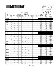
3.2.5 Mechanical Dimensions<br />
*<br />
Please note airflow directions<br />
*<br />
Please note airflow directions<br />
MG.12.P2.02 15
Mechanical Installation<br />
<strong>Armstrong</strong> <strong>IVS</strong> <strong>102</strong> High Power <strong>Operating</strong> <strong>Instructions</strong><br />
3<br />
*<br />
Please note airflow directions<br />
16 MG.12.P2.02
3 3<br />
Mechanical Installation<br />
<strong>Armstrong</strong> <strong>IVS</strong> <strong>102</strong> High Power <strong>Operating</strong> <strong>Instructions</strong><br />
*<br />
Please note airflow directions<br />
MG.12.P2.02 17
Mechanical Installation<br />
<strong>Armstrong</strong> <strong>IVS</strong> <strong>102</strong> High Power <strong>Operating</strong> <strong>Instructions</strong><br />
3<br />
1) Minimum clearance from ceiling<br />
F1 IP 21/54 - NEMA 1/12 F3 IP 21/54 - NEMA 1/12<br />
18 MG.12.P2.02
Mechanical Installation<br />
<strong>Armstrong</strong> <strong>IVS</strong> <strong>102</strong> High Power <strong>Operating</strong> <strong>Instructions</strong><br />
F2 IP 21/54 - NEMA 1/12 F4 IP 21/54 - NEMA 1/12<br />
1) Minimum clearance from ceiling<br />
3 3<br />
MG.12.P2.02 19
Mechanical Installation<br />
<strong>Armstrong</strong> <strong>IVS</strong> <strong>102</strong> High Power <strong>Operating</strong> <strong>Instructions</strong><br />
3<br />
Mechanical dimensions , Frame size D<br />
Frame Size D1 D2 D3 D4<br />
110 - 132 kW at 400 V<br />
(380 - 480 V)<br />
45 - 160 kW at 690 V<br />
(525-690 V)<br />
160 - 250 kW at 400 V<br />
(380 - 480 V)<br />
200 - 400 kW at 690 V<br />
(525-690 V)<br />
110 - 132 kW at 400 V<br />
(380 - 480 V)<br />
45 - 160 kW at 690 V<br />
(525-690 V)<br />
160 - 250 kW at 400 V<br />
(380 - 480 V)<br />
200 - 400 kW at 690 V<br />
(525-690 V)<br />
IP<br />
NEMA<br />
21<br />
Type 1<br />
54<br />
Type 12<br />
21<br />
Type 1<br />
54<br />
Type 12<br />
00<br />
Chassis<br />
00<br />
Chassis<br />
Shipping dimensions Height 650 mm 650 mm 650 mm 650 mm 650 mm 650 mm<br />
Width 1730 mm 1730 mm 1730 mm 1730 mm 1220 mm 1490 mm<br />
Depth 570 mm 570 mm 570 mm 570 mm 570 mm 570 mm<br />
Drive dimensions Height 1209 mm 1209 mm 1589 mm 1589 mm 1046 mm 1327 mm<br />
Width 420 mm 420 mm 420 mm 420 mm 408 mm 408 mm<br />
Depth 380 mm 380 mm 380 mm 380 mm 375 mm 375 mm<br />
Max weight 104 kg 104 kg 151 kg 151 kg 91 kg 138 kg<br />
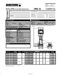
Mechanical dimensions, frame size E and F<br />
Frame Size E1 E2 F1 F2 F3 F4<br />
315 - 450 kW at 400<br />
V<br />
(380 - 480 V)<br />
450 - 630 kW at 690<br />
V<br />
(525-690 V)<br />
315 - 450 kW at 400<br />
V<br />
(380 - 480 V)<br />
450 - 630 kW at 690<br />
V<br />
(525-690 V)<br />
500 - 710 kW at 400<br />
V<br />
(380 - 480 V)<br />
710 - 900 kW at 690<br />
V<br />
(525-690 V)<br />
800 - 1000 kW at 400<br />
V<br />
(380 - 480 V)<br />
1000 - 1200 kW at<br />
690 V<br />
(525-690 V)<br />
500 - 710 kW at 400<br />
V<br />
(380 - 480 V)<br />
710 - 900 kW at 690<br />
V<br />
(525-690 V)<br />
800 - 1000 kW at 400<br />
V<br />
(380 - 480 V)<br />
1000 - 1400 kW at<br />
690 V<br />
(525-690 V)<br />
IP<br />
NEMA<br />
Shipping<br />
dimensions<br />
Drive<br />
dimensions<br />
Height<br />
21, 54<br />
Type 1/ Type 12<br />
00<br />
Chassis<br />
21, 54<br />
Type 1/ Type 12<br />
21, 54<br />
Type 1/ Type 12<br />
21, 54<br />
Type 1/ Type 12<br />
21, 54<br />
Type 1/ Type 12<br />
840 mm 831 mm 2324 mm 2324 mm 2324 mm 2324 mm<br />
Width 2197 mm 1705 mm 1569 mm 1962 mm 2159 mm 2559 mm<br />
Depth 736 mm 736 mm 1130 mm 1130 mm 1130 mm 1130 mm<br />
Height 2000 mm 1547 mm 2204 2204 2204 2204<br />
Width 600 mm 585 mm 1400 1800 2000 2400<br />
Depth 494 mm 498 mm 606 606 606 606<br />
Max<br />
weight<br />
313 kg 277 kg 1004 1246 1299 1541<br />
20 MG.12.P2.02
3 3<br />
Mechanical Installation<br />
<strong>Armstrong</strong> <strong>IVS</strong> <strong>102</strong> High Power <strong>Operating</strong> <strong>Instructions</strong><br />
3.2.6 Rated Power<br />
Frame size D1 D2 D3 D4<br />
Enclosure IP 21/54 21/54 00 00<br />
protection NEMA Type 1/ Type 12 Type 1/ Type 12 Chassis Chassis<br />
110 - 132 kW at 400 V 150 - 250 kW at 400 V 110 - 132 kW at 400 V 150 - 250 kW at 400 V<br />
Normal overload<br />
(380 - 480 V)<br />
(380 - 480 V)<br />
(380 - 480 V)<br />
(380 - 480 V)<br />
rated power - 110%<br />
45 - 160 kW at 690 V 200 - 400 kW at 690 V 45 - 160 kW at 690 V 200 - 400 kW at 690 V<br />
overload torque<br />
(525-690 V)<br />
(525-690 V)<br />
(525-690 V)<br />
(525-690 V)<br />
Frame size E1 E2 F1/F3 F2/F4<br />
IP 21/54 00 21/54 21/54<br />
Enclosure<br />
NEM<br />
protection<br />
Type 1/ Type 12 Chassis Type 1/ Type 12 Type 1/ Type 12<br />
A<br />
315 - 450 kW at 400 V 315 - 450 kW at 400 V 500 - 710 kW at 400 V<br />
800 - 1000 kW at 400 V<br />
Normal overload<br />
(380 - 480 V)<br />
(380 - 480 V)<br />
(380 - 480 V)<br />
(380 - 480 V)<br />
rated power - 110%<br />
450 - 630 kW at 690 V 450 - 630 kW at 690 V 710 - 900 kW at 690 V 1000 - 1400 kW at 690 V<br />
overload torque<br />
(525-690 V)<br />
(525-690 V)<br />
(525-690 V)<br />
(525-690 V)<br />
NOTE<br />
The F frames have four different sizes, F1, F2, F3 and F4 The<br />
F1 and F2 consist of an inverter cabinet on the right and<br />
rectifier cabinet on the left. The F3 and F4 have an additional<br />
options cabinet left of the rectifier cabinet. The F3 is an F1<br />
with an additional options cabinet. The F4 is an F2 with an<br />
additional options cabinet.<br />
MG.12.P2.02 21
Mechanical Installation<br />
<strong>Armstrong</strong> <strong>IVS</strong> <strong>102</strong> High Power <strong>Operating</strong> <strong>Instructions</strong><br />
3.3 Mechanical Installation<br />
3<br />
Preparation of the mechanical installation of the frequency converter must be done carefully to ensure a proper result and to<br />
avoid additional work during installation. Start taking a close look at the mechanical drawings at the end of this instruction to<br />
become familiar with the space demands.<br />
3.3.1 Tools Needed<br />
To perform the mechanical installation the following tools are needed:<br />
• Drill with 10 or 12 mm drill<br />
• Tape measure<br />
• Wrench with relevant metric sockets (7-17 mm)<br />
• Extensions to wrench<br />
• Sheet metal punch for conduits or cable glands in IP 21/Nema 1 and IP 54 units<br />
• Lifting bar to lift the unit (rod or tube max. Ø 25 mm (1 inch), able to lift minimum 400 kg (880 lbs)).<br />
• Crane or other lifting aid to place the frequency converter in position<br />
• A Torx T50 tool is needed to install the E1 in IP21 and IP54 enclosure types.<br />
3.3.2 General Considerations<br />
Space<br />
Ensure proper space above and below the frequency converter to allow airflow and cable access. In addition space in front of<br />
the unit must be considered to enable opening of the door of the panel.<br />
Illustration 3.10 Space in front of IP21/IP54 enclosure type, frame<br />
size F1<br />
Illustration 3.8 Space in front of IP21/IP54 enclosure type, frame<br />
size D1 and D2 .<br />
Illustration 3.11 Space in front of IP21/IP54 enclosure type, frame<br />
size F3<br />
Illustration 3.9 Space in front of IP21/IP54 enclosure type, frame<br />
size E1.<br />
Illustration 3.12 Space in front of IP21/IP54 enclosure type, frame<br />
size F2<br />
22 MG.12.P2.02
Mechanical Installation<br />
<strong>Armstrong</strong> <strong>IVS</strong> <strong>102</strong> High Power <strong>Operating</strong> <strong>Instructions</strong><br />
Illustration 3.13 Space in front of IP21/IP54 enclosure type, frame<br />
size F4<br />
3 3<br />
Wire access<br />
Ensure that proper cable access is present including necessary bending allowance. As the IP00 enclosure is open to the bottom<br />
cables must be fixed to the back panel of the enclosure where the frequency converter is mounted, i.e. by using cable clamps.<br />
NOTE<br />
All cable lugs/ shoes must mount within the width of the<br />
terminal bus bar.<br />
MG.12.P2.02 23
Mechanical Installation<br />
<strong>Armstrong</strong> <strong>IVS</strong> <strong>102</strong> High Power <strong>Operating</strong> <strong>Instructions</strong><br />
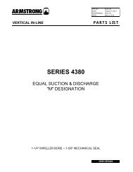
3.3.3 Terminal Locations - Frame size D<br />
Take the following position of the terminals into consideration when you design for cables access.<br />
3<br />
Illustration 3.14 Position of power connections, frame size D3 and D4<br />
24 MG.12.P2.02
3 3<br />
Mechanical Installation<br />
<strong>Armstrong</strong> <strong>IVS</strong> <strong>102</strong> High Power <strong>Operating</strong> <strong>Instructions</strong><br />
Illustration 3.15 Position of power connections with disconnect switch, frame size D1 and D2<br />
Be aware that the power cables are heavy and hard to bend. Consider the optimum position of the frequency converter for<br />
ensuring easy installation of the cables.<br />
MG.12.P2.02 25
Mechanical Installation<br />
<strong>Armstrong</strong> <strong>IVS</strong> <strong>102</strong> High Power <strong>Operating</strong> <strong>Instructions</strong><br />
NOTE<br />
All D frames are available with standard input terminals or<br />
disconnect switch. All terminal dimensions can be found in<br />
the following table.<br />
3<br />
IP 21 (NEMA 1) / IP 54 (NEMA 12)<br />
IP 00 / Chassis<br />
Frame size D1 Frame size D2 Frame size D3 Frame size D4<br />
A 277 (10.9) 379 (14.9) 119 (4.7) 122 (4.8)<br />
B 227 (8.9) 326 (12.8) 68 (2.7) 68 (2.7)<br />
C 173 (6.8) 273 (10.8) 15 (0.6) 16 (0.6)<br />
D 179 (7.0) 279 (11.0) 20.7 (0.8) 22 (0.8)<br />
E 370 (14.6) 370 (14.6) 363 (14.3) 363 (14.3)<br />
F 300 (11.8) 300 (11.8) 293 (11.5) 293 (11.5)<br />
G 222 (8.7) 226 (8.9) 215 (8.4) 218 (8.6)<br />
H 139 (5.4) 142 (5.6) 131 (5.2) 135 (5.3)<br />
I 55 (2.2) 59 (2.3) 48 (1.9) 51 (2.0)<br />
J 354 (13.9) 361 (14.2) 347 (13.6) 354 (13.9)<br />
K 284 (11.2) 277 (10.9) 277 (10.9) 270 (10.6)<br />
L 334 (13.1) 334 (13.1) 326 (12.8) 326 (12.8)<br />
M 250 (9.8) 250 (9.8) 243 (9.6) 243 (9.6)<br />
N 167 (6.6) 167 (6.6) 159 (6.3) 159 (6.3)<br />
O 261 (10.3) 260 (10.3) 261 (10.3) 261 (10.3)<br />
P 170 (6.7) 169 (6.7) 170 (6.7) 170 (6.7)<br />
Q 120 (4.7) 120 (4.7) 120 (4.7) 120 (4.7)<br />
R 256 (10.1) 350 (13.8) 98 (3.8) 93 (3.7)<br />
S 308 (12.1) 332 (13.0) 301 (11.8) 324 (12.8)<br />
T 252 (9.9) 262 (10.3) 245 (9.6) 255 (10.0)<br />
U 196 (7.7) 192 (7.6) 189 (7.4) 185 (7.3)<br />
V 260 (10.2) 273 (10.7) 260 (10.2) 273 (10.7)<br />
Table 3.1 Cable positions as shown in drawings above. Dimensions in mm (inch).<br />
26 MG.12.P2.02
3 3<br />
Mechanical Installation<br />
<strong>Armstrong</strong> <strong>IVS</strong> <strong>102</strong> High Power <strong>Operating</strong> <strong>Instructions</strong><br />
3.3.4 Terminal Locations - Frame size E<br />
Terminal Locations - E1<br />
Take the following position of the terminals into consideration when designing the cable access.<br />
Illustration 3.16 IP21 (NEMA Type 1) and IP54 (NEMA Type 12) enclosure power connection positions<br />
MG.12.P2.02 27
Mechanical Installation<br />
<strong>Armstrong</strong> <strong>IVS</strong> <strong>102</strong> High Power <strong>Operating</strong> <strong>Instructions</strong><br />
3<br />
Illustration 3.17 IP21 (NEMA type 1) and IP54 (NEMA type 12) enclosure power connection positions (detail B)<br />
28 MG.12.P2.02
3 3<br />
Mechanical Installation<br />
<strong>Armstrong</strong> <strong>IVS</strong> <strong>102</strong> High Power <strong>Operating</strong> <strong>Instructions</strong><br />
Illustration 3.18 IP21 (NEMA type 1) and IP54 (NEMA type 12) enclosure power connection position of disconnect switch<br />
Frame size Unit type Dimension for disconnect terminal<br />
IP54/IP21 UL AND NEMA1/NEMA12<br />
E1<br />
250/315 kW (400V) AND 355/450-500/630<br />
KW (690 V)<br />
381 (15.0) 253 (9.9) 253 (9.9) 431 (17.0) 562 (22.1) N/A<br />
315/355-400/450 kW (400V) 371 (14.6) 371 (14.6) 341 (13.4) 431 (17.0) 431 (17.0) 455 (17.9)<br />
MG.12.P2.02 29
Mechanical Installation<br />
<strong>Armstrong</strong> <strong>IVS</strong> <strong>102</strong> High Power <strong>Operating</strong> <strong>Instructions</strong><br />
Terminal locations - Frame size E2<br />
Take the following position of the terminals into consideration when designing the cable access.<br />
3<br />
Illustration 3.19 IP00 enclosure power connection positions<br />
30 MG.12.P2.02
3 3<br />
Mechanical Installation<br />
<strong>Armstrong</strong> <strong>IVS</strong> <strong>102</strong> High Power <strong>Operating</strong> <strong>Instructions</strong><br />
Illustration 3.20 IP00 enclosure power connection positions<br />
Illustration 3.21 IP00 enclosure power connections positions of disconnect switch<br />
Note that the power cables are heavy and difficult to bend. Consider the optimum position of the frequency converter for<br />
ensuring easy installation of the cables.<br />
MG.12.P2.02 31
Mechanical Installation<br />
<strong>Armstrong</strong> <strong>IVS</strong> <strong>102</strong> High Power <strong>Operating</strong> <strong>Instructions</strong><br />
Each terminal allows use of up to 4 cables with cable lugs or use of standard box lug. Earth is connected to relevant termination<br />
point in the drive.<br />
3<br />
Illustration 3.22 Terminal in details<br />
NOTE<br />
Power connections can be made to positions A or B<br />
Frame size Unit type Dimension for disconnect terminal<br />
IPOO/CHASSIS A B C D E F<br />
E2<br />
250/315 kW (400V) AND 355/450-500/630<br />
KW (690 V)<br />
381 (15.0) 245 (9.6) 334 (13.1) 423 (16.7) 256 (10.1) N/A<br />
315/355-400/450 kW (400V) 383 (15.1) 244 (9.6) 334 (13.1) 424 (16.7) 109 (4.3) 149 (5.8)<br />
32 MG.12.P2.02
3 3<br />
Mechanical Installation<br />
<strong>Armstrong</strong> <strong>IVS</strong> <strong>102</strong> High Power <strong>Operating</strong> <strong>Instructions</strong><br />
3.3.5 Terminal Locations - Frame size F<br />
Terminal locations - Frame size F1 and F3<br />
Illustration 3.23 Terminal locations - Inverter Cabinet - F1 and F3 (front, left and right side view). The gland plate is 42 mm below .0 level.<br />
1) Earth ground bar<br />
2) Motor terminals<br />
3) Brake terminals<br />
Illustration 3.24 Terminal Locations - Regen Terminals - F1 and F3<br />
MG.12.P2.02 33
Mechanical Installation<br />
<strong>Armstrong</strong> <strong>IVS</strong> <strong>102</strong> High Power <strong>Operating</strong> <strong>Instructions</strong><br />
Terminal locations - Frame size F2 and F4<br />
3<br />
Illustration 3.25 Terminal locations - Inverter Cabinet - F2 and F4 (front, left and right side view). The gland plate is 42 mm below .0 level.<br />
1) Earth ground bar<br />
Illustration 3.26 Terminal Locations - Regen Terminals - F2 and F4<br />
34 MG.12.P2.02
3 3<br />
Mechanical Installation<br />
<strong>Armstrong</strong> <strong>IVS</strong> <strong>102</strong> High Power <strong>Operating</strong> <strong>Instructions</strong><br />
Terminal locations - Rectifier (F1, F2, F3 and F4)<br />
Illustration 3.27 Terminal locations - Rectifier (Left side, front and right side view). The gland plate is 42 mm below .0 level.<br />
1) Loadshare Terminal (-)<br />
2) Earth ground bar<br />
3) Loadshare Terminal (+)<br />
Terminal locations - Options Cabinet (F3 and F4)<br />
Illustration 3.28 Terminal locations - Options Cabinet (Left side, front and right side view). The gland plate is 42 mm below .0 level.<br />
1) Earth ground bar<br />
MG.12.P2.02 35
Mechanical Installation<br />
<strong>Armstrong</strong> <strong>IVS</strong> <strong>102</strong> High Power <strong>Operating</strong> <strong>Instructions</strong><br />
Terminal locations - Options Cabinet with circuit breaker/ molded case switch (F3 and F4)<br />
3<br />
Illustration 3.29 Terminal locations - Options Cabinet with circuit breaker/ molded case switch (Left side, front and right side view). The gland<br />
plate is 42 mm below .0 level.<br />
1) Earth ground bar<br />
Power size 2 3 4 5<br />
500 kW (480 V), 710-800 kW<br />
34.9 86.9 122.2 174.2<br />
(690 V)<br />
560-1000 kW (480 V),<br />
46.3 98.3 119.0 171.0<br />
900-1400 kW (690 V)<br />
Table 3.2 Dimension for terminal<br />
36 MG.12.P2.02
Mechanical Installation<br />
<strong>Armstrong</strong> <strong>IVS</strong> <strong>102</strong> High Power <strong>Operating</strong> <strong>Instructions</strong><br />
3.3.6 Cooling and Airflow<br />
Cooling<br />
Cooling can be obtained in different ways, by using the cooling ducts in the bottom and the top of the unit, by taking air in and<br />
out the back of the unit or by combining the cooling possibilities.<br />
Duct cooling<br />
A dedicated option has been developed to optimize installation of IP00/chassis frequency converters in Rittal TS8 enclosures<br />
utilizing the fan of the frequency converter for forced air cooling of the backchannel. The air out the top of the enclosure could<br />
but ducted outside a facility so the heat loses from the backchannel are not dissipated within the control room reducing airconditioning<br />
requirements of the facility.<br />
Please see Installation of Duct Cooling Kit in Rittal enclosures, for further information.<br />
3 3<br />
Back cooling<br />
The backchannel air can also be ventilated in and out the back of a Rittal TS8 enclosure. This offers a solution where the<br />
backchannel could take air from outside the facility and return the heat loses outside the facility thus reducing air-conditioning<br />
requirements.<br />
NOTE<br />
A door fan(s) is required on the enclosure to remove the heat<br />
losses not contained in the backchannel of the drive and any<br />
additional losses generated from other components installed<br />
inside the enclosure. The total required air flow must be<br />
calculated so that the appropriate fans can be selected.<br />
Some enclosure manufacturers offer software for performing<br />
the calculations (i.e. Rittal Therm software). If the drive is the<br />
only heat generating component in the enclosure, the<br />
minimum airflow required at an ambient temperature of<br />
45 o C for the D3 and D4 drives is 391 m 3 /h (230 cfm). The<br />
minimum airflow required at an ambient temperature of<br />
45 o C for the E2 drive is 782 m 3 /h (460 cfm).<br />
Airflow<br />
The necessary airflow over the heat sink must be secured. The flow rate is shown below.<br />
Enclosure protection Frame size Door fan(s) / Top fan airflow Heatsink fan(s)<br />
IP21 / NEMA 1<br />
D1 and D2 170 m 3 /h (100 cfm) 765 m 3 /h (450 cfm)<br />
IP54 / NEMA 12<br />
E1 P315T5, P450T7, P500T7 340 m 3 /h (200 cfm) 1105 m 3 /h (650 cfm)<br />
E1 P355-P450T5, P560-P630T7 340 m 3 /h (200 cfm) 1445 m 3 /h (850 cfm)<br />
IP21 / NEMA 1 F1, F2, F3 and F4 700 m 3 /h (412 cfm)* 985 m 3 /h (580 cfm)*<br />
IP54 / NEMA 12 F1, F2, F3 and F4 525 m 3 /h (309 cfm)* 985 m 3 /h (580 cfm)*<br />
IP00 / Chassis D3 and D4 255 m 3 /h (150 cfm) 765 m 3 /h (450 cfm)<br />
E2 P315T5, P450T7, P500T7 255 m 3 /h (150 cfm) 1105 m 3 /h (650 cfm)<br />
E2 P355-P450T5, P560-P630T7 255 m 3 /h (150 cfm) 1445 m 3 /h (850 cfm)<br />
* Airflow per fan. Frame size F contain multiple fans.<br />
Table 3.3 Heatsink Air Flow<br />
MG.12.P2.02 37
Mechanical Installation<br />
<strong>Armstrong</strong> <strong>IVS</strong> <strong>102</strong> High Power <strong>Operating</strong> <strong>Instructions</strong><br />
External ducts<br />
If additional duct work is added externally to the Rittal cabinet the pressure drop in the ducting must be calculated. Use the<br />
charts below to derate the frequency converter according to the pressure drop.<br />
3<br />
Illustration 3.30 D frame Derating vs. Pressure Change<br />
Drive air flow: 450 cfm (765 m 3 /h)<br />
Illustration 3.31 E frame Derating vs. Pressure Change (Small Fan), P315T5 and P450T7-P500T7<br />
Drive air flow: 650 cfm (1105 m 3 /h)<br />
Illustration 3.32 E frame Derating vs. Pressure Change (Large Fan), P355T5-P450T5 and P560T7-P630T7<br />
Drive air flow: 850 cfm (1445 m 3 /h)<br />
38 MG.12.P2.02
3 3<br />
Mechanical Installation<br />
<strong>Armstrong</strong> <strong>IVS</strong> <strong>102</strong> High Power <strong>Operating</strong> <strong>Instructions</strong><br />
Illustration 3.33 F1, F2, F3, F4 frame Derating vs. Pressure Change<br />
Drive air flow: 580 cfm (985 m 3 /h)<br />
3.3.7 Installation on the Wall - IP21 (NEMA 1) and IP54 (NEMA 12) Units<br />
This only applies to frame sizes D1 and D2 . It must be considered where to install the unit.<br />
Take the relevant points into consideration before you select the final installation site:<br />
• Free space for cooling<br />
• Access to open the door<br />
• Cable entry from the bottom<br />
Mark the mounting holes carefully using the mounting template on the wall and drill the holes as indicated. Ensure proper<br />
distance to the floor and the ceiling for cooling. A minimum of 225 mm (8.9 inch) below the frequency converter is needed.<br />
Mount the bolts at the bottom and lift the frequency converter up on the bolts. Tilt the frequency converter against the wall and<br />
mount the upper bolts. Tighten all four bolts to secure the frequency converter against the wall.<br />
Illustration 3.34 Lifting method for mounting drive on wall<br />
MG.12.P2.02 39
Mechanical Installation<br />
<strong>Armstrong</strong> <strong>IVS</strong> <strong>102</strong> High Power <strong>Operating</strong> <strong>Instructions</strong><br />
3.3.8 Gland/Conduit Entry - IP21 (NEMA 1) and IP54 (NEMA12)<br />
Cables are connected through the gland plate from the bottom. Remove the plate and plan where to place the entry for the<br />
glands or conduits. Prepare holes in the marked area on the drawing.<br />
3<br />
NOTE<br />
The gland plate must be fitted to the frequency converter to<br />
ensure the specified protection degree, as well as ensuring<br />
proper cooling of the unit. If the gland plate is not mounted,<br />
the frequency converter may trip on Alarm 69, Pwr. Card<br />
Temp<br />
Illustration 3.35 Example of proper installation of the gland plate.<br />
Frame size D1 + D2<br />
Frame size E1<br />
Cable entries viewed from the bottom of the frequency converter - 1) Mains side 2) Motor side<br />
40 MG.12.P2.02
3 3<br />
Mechanical Installation<br />
<strong>Armstrong</strong> <strong>IVS</strong> <strong>102</strong> High Power <strong>Operating</strong> <strong>Instructions</strong><br />
Frame size F1<br />
Frame size F2<br />
Frame size F3<br />
Frame size F4<br />
F1-F4: Cable entries viewed from the bottom of the frequency converter - 1) Place conduits in marked areas<br />
MG.12.P2.02 41
Mechanical Installation<br />
<strong>Armstrong</strong> <strong>IVS</strong> <strong>102</strong> High Power <strong>Operating</strong> <strong>Instructions</strong><br />
3<br />
Illustration 3.36 Mounting of bottom plate,frame size E1.<br />
The bottom plate of the E1 can be mounted from either in- or outside of the enclosure, allowing flexibility in the installation<br />
process, i.e. if mounted from the bottom the glands and cables can be mounted before the frequency converter is placed on the<br />
pedestal.<br />
3.3.9 IP21 Drip Shield Installation (Frame size D1 and D2)<br />
To comply with the IP21 rating, a separate drip shield is to be installed as explained below:<br />
• Remove the two front screws<br />
• Insert the drip shield and replace screws<br />
• Torque the screws to 5,6 Nm (50 in-lbs)<br />
Illustration 3.37 Drip shield installation.<br />
42 MG.12.P2.02
Mechanical Installation<br />
<strong>Armstrong</strong> <strong>IVS</strong> <strong>102</strong> High Power <strong>Operating</strong> <strong>Instructions</strong><br />
3.4 Field Installation of Options<br />
3.4.1 Installation of Duct Cooling Kit in Rittal Enclosures<br />
This section deals with the installation of IP00 / chassis enclosed frequency converters with duct work cooling kits in Rittal<br />
enclosures. In addition to the enclosure a 200 mm base/plinth is required.<br />
3 3<br />
Illustration 3.38 Installation of IP00 in Rittal TS8 enclosure.<br />
The minimum enclosure dimension is:<br />
• D3 and D4 frame: Depth 500 mm and width 600 mm.<br />
• E2 frame: Depth 600 mm and width 800 mm.<br />
The maximum depth and width are as required by the installation. When using multiple frequency converters in one enclosure it<br />
is recommended that each drive is mounted on its own back panel and supported along the mid-section of the panel. These<br />
duct work kits do not support the “in frame” mounting of the panel (see Rittal TS8 catalogue for details). The duct work cooling<br />
kits listed in the table below are suitable for use only with IP 00 / Chassis frequency converters in Rittal TS8 IP 20 and UL and<br />
NEMA 1 and IP 54 and UL and NEMA 12 enclosures.<br />
MG.12.P2.02 43
Mechanical Installation<br />
<strong>Armstrong</strong> <strong>IVS</strong> <strong>102</strong> High Power <strong>Operating</strong> <strong>Instructions</strong><br />
3<br />
NOTE<br />
For the E2 frames it is important to mount the plate at the<br />
absolute rear of the Rittal enclosure due to the weight of the<br />
frequency converter.<br />
NOTE<br />
A doorfan(s) is required on the enclosure to remove the heat<br />
losses not contained in the backchannel of the drive and any<br />
additional losses generated from other components installed<br />
inside the enclosure. The total required air flow must be<br />
calculated so that the appropriate fans can be selected.<br />
Some enclosure manufacturers offer software for performing<br />
the calculations (i.e. Rittal Therm software). If the drive is the<br />
only heat generating component in the enclosure, the<br />
minimum airflow required at an ambient temperature of<br />
45°C for the D3 and D4 drives is 391 m 3 /h (230 cfm). The<br />
minimum airflow required at an ambient temperature of<br />
45°C for the E2 drive is 782 m 3 /h (460 cfm).<br />
Ordering Information<br />
Rittal TS-8 Enclosure Frame D3 Kit Part No. Frame D4Kit Part No. Frame E2 Part No.<br />
1800 mm 176F1824 176F1823 Not possible<br />
2000 mm 176F1826 176F1825 176F1850<br />
2200 mm 176F0299<br />
NOTE<br />
Please see the Duct Kit Instruction Manual, 175R5640, for<br />
further information<br />
External ducts<br />
If additional duct work is added externally to the Rittal cabinet the pressure drop in the ducting must be calculated. Please see<br />
section Cooling and Airflow for further information.<br />
3.4.2 Installation of Top-only Duct Cooling Kit<br />
This description is for the installation of the top section only of the back-channel cooling kits available for frame sizes D3, D4 and<br />
E2. In addition to the enclosure a 200 mm vented pedestal is required.<br />
The minimum enclosure depth is 500 mm (600 mm for E2 frame) and the minimum enclosure width is 600 mm (800 mm for E2<br />
frame). The maximum depth and width are as required by the installation. When using multiple frequency converters in one<br />
enclosure mount each drive on its own back panel and support along the mid-section of the panel. The back-channel cooling<br />
kits are very similar in construction for all frames. The D3 and D4 kits do not support “in frame” mounting of the frequency<br />
converters. The E2 kit is mounted “in frame” for additional support of the frequency converter.<br />
Using these kits as described removes 85% of the losses via the back channel using the drive’s main heat sink fan. The remaining<br />
15% must be removed via the door of the enclosure.<br />
NOTE<br />
Please see the Top-Only Back-Channel Cooling Kit Instruction,<br />
175R1107, for further information.<br />
Ordering information<br />
Frame size D3 and D4: 176F1775<br />
Frame size E2: 176F1776<br />
44 MG.12.P2.02
Mechanical Installation<br />
<strong>Armstrong</strong> <strong>IVS</strong> <strong>102</strong> High Power <strong>Operating</strong> <strong>Instructions</strong><br />
3.4.3 Installation of Top and Bottom Covers for Rittal Enclosures<br />
The top and bottom covers, installed onto IP00 frequency converters, direct the heat sink cooling air in and out the back of the<br />
frequency converter. The kits are applicable to IP00 drive frames D3, D4 and E2. These kits are designed and tested to be used<br />
with IP00/Chassis drives in Rittal TS8 enclosures.<br />
Notes:<br />
1. If external duct work is added to the exhaust path of the drive, additional back pressure will be created that will reduce<br />
the cooling of the drive. The drive must be derated to accommodate the reduced cooling. First, the pressure drop<br />
must be calculated, then refer to the derating tables located earlier in this section.<br />
2. A doorfan(s) is required on the enclosure to remove the heat losses not contained in the backchannel of the drive and<br />
any additional losses generated from other components installed inside the enclosure. The total required air flow must<br />
be calculated so that the appropriate fans can be selected. Some enclosure manufacturers offer software for<br />
performing the calculations (i.e. Rittal Therm software).<br />
If the frequency converter is the only heat generating component in the enclosure, the minimum airflow required at an<br />
ambient temperature of 45°C for the D3 and D4 frame drives is 391 m 3 /h (230 cfm). The minimum airflow required at<br />
an ambient temperature of 45°C for the E2 frame drive is 782 m 3 /h (460 cfm).<br />
3 3<br />
NOTE<br />
Please see the instruction for Top and Bottom Covers - Rittal<br />
Enclosure, 177R0076, for further information.<br />
Ordering information<br />
Frame size D3: 176F1781<br />
Frame size D4: 176F1782<br />
Frame size E2: 176F1783<br />
3.4.4 Installation of Top and Bottom Covers<br />
Top and bottom covers can be installed on frame sizes D3, D4 and E2. These kits are designed to be used to direct the backchannel<br />
airflow in and out the back of the drive as opposed to in the bottom and out the top of the drive (when the drives are<br />
being mounted directly on a wall or inside a welded enclosure).<br />
Notes:<br />
1. If external duct work is added to the exhaust path of the drive, additional back pressure will be created that will reduce<br />
the cooling of the drive. The drive must be derated to accommodate the reduced cooling. First, the pressure drop<br />
must be calculated, then refer to the derating tables located earlier in this section.<br />
2. A doorfan(s) is required on the enclosure to remove the heat losses not contained in the backchannel of the drive and<br />
any additional losses generated from other components installed inside the enclosure. The total required air flow must<br />
be calculated so that the appropriate fans can be selected. Some enclosure manufacturers offer software for<br />
performing the calculations (i.e. Rittal Therm software).<br />
If the frequency converter is the only heat generating component in the enclosure, the minimum airflow required at an<br />
ambient temperature of 45°C for the D3 and D4 frame drives is 391 m 3 /h (230 cfm). The minimum airflow required at<br />
an ambient temperature of 45°C for the E2 frame drive is 782 m 3 /h (460 cfm).<br />
NOTE<br />
Please see theTop and Bottom Covers Only Instruction,<br />
175R1106, for further information.<br />
Ordering information<br />
Frame size D3 and D4: 176F1862<br />
Frame size E2: 176F1861<br />
MG.12.P2.02 45
Mechanical Installation<br />
<strong>Armstrong</strong> <strong>IVS</strong> <strong>102</strong> High Power <strong>Operating</strong> <strong>Instructions</strong><br />
3.4.5 Outside Installation/ NEMA 3R Kit for Rittal Enclosures<br />
3<br />
This section is for the installation of NEMA 3R kits available for the frequency converter frames D3, D4 and E2. These kits are<br />
designed and tested to be used with IP00/ Chassis versions of these frames in Rittal TS8 NEMA 3R or NEMA 4 enclosures. The<br />
NEMA-3R enclosure is an outdoor enclosure that provides a degree of protection against rain and ice. The NEMA-4 enclosure is<br />
an outdoor enclosure that provides a greater degree of protection against weather and hosed water.<br />
The minimum enclosure depth is 500 mm (600 mm for E2 frame) and the kit is designed for a 600 mm (800 mm for E2 frame)<br />
wide enclosure. Other enclosure widths are possible, however additional Rittal hardware is required. The maximum depth and<br />
width are as required by the installation.<br />
NOTE<br />
The current rating of drives in D3 and D4 frames are de-rated<br />
by 3%, when adding the NEMA 3R kit. Drives in E2 frames<br />
require no derating.<br />
NOTE<br />
A doorfan(s) is required on the enclosure to remove the heat<br />
losses not contained in the backchannel of the drive and any<br />
additional losses generated from other components installed<br />
inside the enclosure. The total required air flow must be<br />
calculated so that the appropriate fans can be selected.<br />
Some enclosure manufacturers offer software for performing<br />
the calculations (i.e. Rittal Therm software). If the drive is the<br />
only heat generating component in the enclosure, the<br />
minimum airflow required at an ambient temperature of<br />
45°C for the D3 and D4 drives is 391 m 3 /h (230 cfm). The<br />
minimum airflow required at an ambient temperature of<br />
45°C for the E2 drive is 782 m 3 /h (460 cfm).<br />
46 MG.12.P2.02
Mechanical Installation<br />
<strong>Armstrong</strong> <strong>IVS</strong> <strong>102</strong> High Power <strong>Operating</strong> <strong>Instructions</strong><br />
Ordering information<br />
Frame size D3: 176F4600<br />
Frame size D4: 176F4601<br />
Frame size E2: 176F1852<br />
NOTE<br />
Please see the instructions 175R5922 for further information.<br />
3.4.6 Outside Installation /NEMA 3R Kit of Industrial Enclosures<br />
3 3<br />
The kits are available for the frame sizes D3, D4 and E2. These kits are designed and tested to be used with IP00/Chassis drives in<br />
welded box construction enclosures with an environmental rating of NEMA-3R or NEMA-4. The NEMA-3R enclosure is a dust<br />
tight, rain tight, ice resistant, outdoor enclosure. The NEMA-4 enclosure is a dust tight and water tight enclosure.<br />
This kit has been tested and complies with UL environmental rating Type-3R.<br />
Note: The current rating of D3 and D4 frame drives are de-rated by 3% when installed in a NEMA- 3R enclosure. E2 frame drives<br />
require no de-rating when installed in a NEMA-3R enclosure.<br />
NOTE<br />
Please see the instruction forOutside Installation /NEMA 3R kit<br />
of industrial enclosures, 175R1068, for further information.<br />
Ordering information<br />
Frame size D3: 176F0296<br />
Frame size D4: 176F0295<br />
Frame size E2: 176F0298<br />
3.4.7 Installation of IP00 to IP20 Kits<br />
The kits can be installed on frame sizes D3, D4, and E2 (IP00).<br />
NOTE<br />
Please see the instruction for Installation of IP20 Kits,<br />
175R1108, for further information.<br />
Ordering information<br />
Frame size D3/D4: 176F1779<br />
Frame size E2: 176FXXXX<br />
3.4.8 Installation of IP00s D3, D4, & E2 Cable Clamp Bracket<br />
The motor cable clamp brackets can be installed on frame sizes D3 and D4 (IP00).<br />
NOTE<br />
Please see the instruction forCable Clamp Bracket Kit,<br />
175R1109, for further information.<br />
Ordering information<br />
Frame size D3: 176F1774<br />
Frame size D4: 176F1746<br />
Frame size E2: 176F1745<br />
MG.12.P2.02 47
Mechanical Installation<br />
<strong>Armstrong</strong> <strong>IVS</strong> <strong>102</strong> High Power <strong>Operating</strong> <strong>Instructions</strong><br />
3.4.9 Installation on Pedestal<br />
3<br />
This section describes the installation of a pedestal unit<br />
available for the frequency converters frames D1 and D2.<br />
This is a 200 mm high pedestal that allows these frames to<br />
be floor mounted. The front of the pedestal has openings for<br />
input air to the power components.<br />
The frequency converter gland plate must be installed to<br />
provide adequate cooling air to the control components of<br />
the frequency converter via the door fan and to maintain the<br />
IP21/NEMA 1 or IP54/NEMA 12 degrees of enclosure<br />
protections.<br />
Illustration 3.39 Drive on pedestal<br />
There is one pedestal that fits both frames D1 and D2. Its ordering number is 176F1827. The pedestal is standard for E1 frame.<br />
48 MG.12.P2.02
3 3<br />
Mechanical Installation<br />
<strong>Armstrong</strong> <strong>IVS</strong> <strong>102</strong> High Power <strong>Operating</strong> <strong>Instructions</strong><br />
NOTE<br />
Please see the Pedestal Kit Instruction Manual, 175R5642, for<br />
further information.<br />
Illustration 3.40 Mounting of drive to pedestal.<br />
3.4.10 Installation of Mains Shield for Frequency Converters<br />
This section is for the installation of a mains shield for the frequency converter series with D1, D2 and E1 frames. It is not possible<br />
to install in the IP00/ Chassis versions as these have included as standard a metal cover. These shields satisfy VBG-4<br />
requirements.<br />
Ordering numbers:<br />
Frames D1 and D2 : 176F0799<br />
Frame E1: 176F1851<br />
NOTE<br />
For further information, please see the Instruction Sheet,<br />
175R5923<br />
3.4.11 F Frame USB Extension Kit<br />
A USB extension cable can be installed into the door of F frame VLT frequency converters.<br />
Ordering number:<br />
176F1784<br />
NOTE<br />
For further information, please see the Instruction Sheet,<br />
177R0091<br />
MG.12.P2.02 49
Mechanical Installation<br />
<strong>Armstrong</strong> <strong>IVS</strong> <strong>102</strong> High Power <strong>Operating</strong> <strong>Instructions</strong><br />
3.4.12 Installation of Input Plate Options<br />
3<br />
This section is for the field installation of input option kits available for frequency converters in all D and E frames.<br />
Do not attempt to remove RFI filters from input plates. Damage may occur to RFI filters if they are removed from the input<br />
plate.<br />
NOTE<br />
Where RFI filters are available, there are two different type of<br />
RFI filters depending on the input plate combination and the<br />
RFI filters interchangeable. Field installable kits in certain<br />
cases are the same for all voltages.<br />
380 - 480 V<br />
380 - 500 V<br />
Fuses Disconnect Fuses RFI RFI Fuses RFI Disconnect<br />
Fuses<br />
D1 All D1 power sizes 176F8442 176F8450 176F8444 176F8448 176F8446<br />
D2 All D2 power sizes 176F8443 176F8441 176F8445 176F8449 176F8447<br />
E1<br />
<strong>IVS</strong> <strong>102</strong>/ : 315 kW 176F0253 176F0255 176F0257 176F0258 176F0260<br />
<strong>IVS</strong> <strong>102</strong>: 250 kW<br />
<strong>IVS</strong> <strong>102</strong>/ : 355 - 450 kW<br />
<strong>IVS</strong> <strong>102</strong>: 315 - 400 kW<br />
176F0254 176F0256 176F0257 176F0259 176F0262<br />
525 - 690 V Fuses Disconnect Fuses RFI RFI Fuses RFI Disconnect<br />
Fuses<br />
D1<br />
<strong>IVS</strong> <strong>102</strong>/ : 45-90 kW 175L8829 175L8828 175L8777 NA NA<br />
<strong>IVS</strong> <strong>102</strong>: 37-75 kW<br />
<strong>IVS</strong> <strong>102</strong>/ : 110-160 kW 175L8442 175L8445 175L8777 NA NA<br />
<strong>IVS</strong> <strong>102</strong>: 90-132 kW<br />
D2 All D2power sizes 175L8827 175L8826 175L8825 NA NA<br />
E1<br />
<strong>IVS</strong> <strong>102</strong>/ : 450-500 kW 176F0253 176F0255 NA NA NA<br />
<strong>IVS</strong> <strong>102</strong>: 355-400 kW<br />
<strong>IVS</strong> <strong>102</strong>/ : 560-630 kW<br />
<strong>IVS</strong> <strong>102</strong>: 500-560 kW<br />
176F0254 176F0258 NA NA NA<br />
NOTE<br />
For further information, please see the Instruction Sheet,<br />
175R5795<br />
3.4.13 Installation of D or E Loadshare Option<br />
The loadshare option can be installed on frame sizes D1, D2, D3, D4, E1 and E2.<br />
NOTE<br />
Please see the Loadshare Terminal Kit <strong>Instructions</strong>, 175R5637<br />
(D frames) or 177R1114 (E frames), for further information.<br />
Ordering information<br />
Frame size D1/D3: 176F8456<br />
Frame size D2/D4: 176F8455<br />
Frame size E1/E2: 176F1843<br />
50 MG.12.P2.02
Mechanical Installation<br />
<strong>Armstrong</strong> <strong>IVS</strong> <strong>102</strong> High Power <strong>Operating</strong> <strong>Instructions</strong><br />
3.5 Frame size F Panel Options<br />
Space Heaters and Thermostat<br />
Mounted on the cabinet interior of frame size F frequency converters, space heaters controlled via automatic thermostat help<br />
control humidity inside the enclosure, extending the lifetime of drive components in damp environments. The thermostat<br />
default settings turn on the heaters at 10° C (50° F) and turn them off at 15.6° C (60° F).<br />
Cabinet Light with Power Outlet<br />
A light mounted on the cabinet interior of frame size F frequency converters increase visibility during servicing and<br />
maintenance. The housing the light includes a power outlet for temporarily powering tools or other devices, available in two<br />
voltages:<br />
• 230V, 50Hz, 2.5A, CE/ENEC<br />
• 120V, 60Hz, 5A, UL/cUL<br />
3 3<br />
Transformer Tap Setup<br />
If the Cabinet Light & Outlet and/or the Space Heaters & Thermostat are installed Transformer T1 requires it taps to be set to the<br />
proper input voltage. A 380-480/ 500 V380-480 V drive will initially be set to the 525 V tap and a 525-690 V drive will be set to<br />
the 690 V tap to insure no over-voltage of secondary equipment occurs if the tap is not changed prior to power being applied.<br />
See the table below to set the proper tap at terminal T1 located in the rectifier cabinet. For location in the drive, see illustration<br />
of rectifier in the Power Connections section.<br />
Input Voltage Range<br />
380V-440V<br />
441V-490V<br />
491V-550V<br />
551V-625V<br />
626V-660V<br />
661V-690V<br />
Tap to Select<br />
400V<br />
460V<br />
525V<br />
575V<br />
660V<br />
690V<br />
NAMUR Terminals<br />
NAMUR is an international association of automation technology users in the process industries, primarily chemical and pharmaceutical<br />
industries in Germany. Selection of this option provides terminals organized and labeled to the specifications of the<br />
NAMUR standard for drive input and output terminals. This requires MCB 112 PTC Thermistor Card and MCB 113 Extended Relay<br />
Card.<br />
RCD (Residual Current Device)<br />
Uses the core balance method to monitor ground fault currents in grounded and high-resistance grounded systems (TN and TT<br />
systems in IEC terminology). There is a pre-warning (50% of main alarm set-point) and a main alarm set-point. Associated with<br />
each set-point is an SPDT alarm relay for external use. Requires an external “window-type” current transformer (supplied and<br />
installed by customer).<br />
• Integrated into the drive’s safe-stop circuit<br />
• IEC 60755 Type B device monitors AC, pulsed DC, and pure DC ground fault currents<br />
• LED bar graph indicator of the ground fault current level from 10–100% of the set-point<br />
• Fault memory<br />
• TEST / RESET button<br />
MG.12.P2.02 51
Mechanical Installation<br />
<strong>Armstrong</strong> <strong>IVS</strong> <strong>102</strong> High Power <strong>Operating</strong> <strong>Instructions</strong><br />
3<br />
Insulation Resistance Monitor (IRM)<br />
Monitors the insulation resistance in ungrounded systems (IT systems in IEC terminology) between the system phase conductors<br />
and ground. There is an ohmic pre-warning and a main alarm set-point for the insulation level. Associated with each set-point is<br />
an SPDT alarm relay for external use. Note: only one insulation resistance monitor can be connected to each ungrounded (IT)<br />
system.<br />
• Integrated into the drive’s safe-stop circuit<br />
• LCD display of the ohmic value of the insulation resistance<br />
• Fault Memory<br />
• INFO, TEST, and RESET buttons<br />
IEC Emergency Stop with Pilz Safety Relay<br />
Includes a redundant 4-wire emergency-stop push-button mounted on the front of the enclosure and a Pilz relay that monitors<br />
it in conjunction with the drive’s safe-stop circuit and the mains contactor located in the options cabinet.<br />
Manual Motor Starters<br />
Provide 3-phase power for electric blowers often required for larger motors. Power for the starters is provided from the load side<br />
of any supplied contactor, circuit breaker, or disconnect switch. Power is fused before each motor starter, and is off when the<br />
incoming power to the drive is off. Up to two starters are allowed (one if a 30A, fuse-protected circuit is ordered). Integrated into<br />
the drive’s safe-stop circuit.<br />
Unit features include:<br />
• Operation switch (on/off)<br />
• Short-circuit and overload protection with test function<br />
• Manual reset function<br />
30 Ampere, Fuse-Protected Terminals<br />
• 3-phase power matching incoming mains voltage for powering auxiliary customer equipment<br />
• Not available if two manual motor starters are selected<br />
• Terminals are off when the incoming power to the drive is off<br />
• Power for the fused protected terminals will be provided from the load side of any supplied contactor, circuit breaker,<br />
or disconnect switch.<br />
24 VDC Power Supply<br />
• 5 amp, 120 W, 24 VDC<br />
• Protected against output over-current, overload, short circuits, and over-temperature<br />
• For powering customer-supplied accessory devices such as sensors, PLC I/O, contactors, temperature probes, indicator<br />
lights, and/or other electronic hardware<br />
• Diagnostics include a dry DC-ok contact, a green DC-ok LED, and a red overload LED<br />
External Temperature Monitoring<br />
Designed for monitoring temperatures of external system components, such as the motor windings and/or bearings. Includes<br />
eight universal input modules plus two dedicated thermistor input modules. All ten modules are integrated into the drive’s<br />
safe-stop circuit and can be monitored via a fieldbus network (requires the purchase of a separate module/bus coupler).<br />
52 MG.12.P2.02
Mechanical Installation<br />
<strong>Armstrong</strong> <strong>IVS</strong> <strong>102</strong> High Power <strong>Operating</strong> <strong>Instructions</strong><br />
Universal inputs (8)<br />
Signal types:<br />
• RTD inputs (including Pt100), 3-wire or 4-wire<br />
• Thermocouple<br />
• Analog current or analog voltage<br />
Additional features:<br />
• One universal output, configurable for analog voltage or analog current<br />
• Two output relays (N.O.)<br />
• Dual-line LC display and LED diagnostics<br />
• Sensor lead wire break, short-circuit, and incorrect polarity detection<br />
• Interface setup software<br />
3 3<br />
Dedicated thermistor inputs (2)<br />
Features:<br />
• Each module capable of monitoring up to six thermistors in series<br />
• Fault diagnostics for wire breakage or short-circuits of sensor leads<br />
• ATEX/UL/CSA certification<br />
• A third thermistor input can be provided by the PTC Thermistor Option Card MCB 112, if necessary<br />
MG.12.P2.02 53
Electrical Installation<br />
<strong>Armstrong</strong> <strong>IVS</strong> <strong>102</strong> High Power <strong>Operating</strong> <strong>Instructions</strong><br />
4 Electrical Installation<br />
4<br />
4.1 Electrical Installation<br />
4.1.1 Power Connections<br />
Cabling and Fusing<br />
NOTE<br />
Cables General<br />
All cabling must comply with national and local regulations<br />
on cable cross-sections and ambient temperature. UL<br />
applications require 75 °C copper conductors. 75 and 90 °C<br />
copper conductors are thermally acceptable for the<br />
frequency converter to use in non UL applications.<br />
The power cable connections are situated as shown below. Dimensioning of cable cross section must be done in accordance<br />
with the current ratings and local legislation. See the Specifications section for details.<br />
For protection of the frequency converter, the recommended fuses must be used or the unit must be with built-in fuses.<br />
Recommended fuses can be seen in the tables of the fuse section. Always ensure that proper fusing is made according to local<br />
regulation.<br />
The mains connection is fitted to the mains switch if this is included.<br />
NOTE<br />
The motor cable must be screened/armoured. If an<br />
unscreened/unarmoured cable is used, some EMC<br />
requirements are not complied with. Use a screened/<br />
armoured motor cable to comply with EMC emission specifications.<br />
For more information, see EMC specifications in the<br />
Design Guide.<br />
See section General Specifications for correct dimensioning of motor cable cross-section and length.<br />
Screening of cables:<br />
Avoid installation with twisted screen ends (pigtails). They spoil the screening effect at higher frequencies. If it is necessary to<br />
break the screen to install a motor isolator or motor contactor, the screen must be continued at the lowest possible HF<br />
impedance.<br />
Connect the motor cable screen to both the de-coupling plate of the frequency converter and to the metal housing of the<br />
motor.<br />
Make the screen connections with the largest possible surface area (cable clamp). This is done by using the supplied installation<br />
devices within the frequency converter.<br />
Cable-length and cross-section:<br />
The frequency converter has been EMC tested with a given length of cable. Keep the motor cable as short as possible to reduce<br />
the noise level and leakage currents.<br />
54 MG.12.P2.02
Electrical Installation<br />
<strong>Armstrong</strong> <strong>IVS</strong> <strong>102</strong> High Power <strong>Operating</strong> <strong>Instructions</strong><br />
Switching frequency:<br />
When frequency converters are used together with Sine-wave filters to reduce the acoustic noise from a motor, the switching<br />
frequency must be set according to the instruction in 14-01 Switching Frequency.<br />
Term. no. 96 97 98 99<br />
U V W PE 1) Motor voltage 0-100% of mains voltage.<br />
3 wires out of motor<br />
U1 V1 W1<br />
PE 1) Delta-connected<br />
W2 U2 V2 6 wires out of motor<br />
U1 V1 W1 PE 1) Star-connected U2, V2, W2<br />
U2, V2 and W2 to be interconnected separately.<br />
1) Protected Earth Connection<br />
NOTE<br />
In motors without phase insulation paper or other insulation<br />
reinforcement suitable for operation with voltage supply<br />
(such as a frequency converter), fit a Sine-wave filter on the<br />
output of the frequency converter.<br />
4 4<br />
MG.12.P2.02 55
Electrical Installation<br />
<strong>Armstrong</strong> <strong>IVS</strong> <strong>102</strong> High Power <strong>Operating</strong> <strong>Instructions</strong><br />
4<br />
Illustration 4.1 Compact IP 21 (NEMA 1) and IP 54 (NEMA 12), frame size D1<br />
Illustration 4.2 Compact IP 21 (NEMA 1) and IP 54 (NEMA 12) with disconnect, fuse and RFI filter, frame size D2<br />
1) AUX Relay 5) Brake<br />
01 02 03 -R +R<br />
04 05 06 81 82<br />
2) Temp Switch 6) SMPS Fuse (see fuse tables for part number)<br />
106 104 105 7) AUX Fan<br />
3) Line 100 101 <strong>102</strong> 103<br />
R S T L1 L2 L1 L2<br />
91 92 93 8) Fan Fuse (see fuse tables for part number)<br />
L1 L2 L3 9) Mains ground<br />
4) Load sharing 10) Motor<br />
-DC +DC U V W<br />
88 89 96 97 98<br />
T1 T2 T3<br />
56 MG.12.P2.02
4 4<br />
Electrical Installation<br />
<strong>Armstrong</strong> <strong>IVS</strong> <strong>102</strong> High Power <strong>Operating</strong> <strong>Instructions</strong><br />
Illustration 4.3 Compact IP 00 (Chassis), frame size D3<br />
MG.12.P2.02 57
Electrical Installation<br />
<strong>Armstrong</strong> <strong>IVS</strong> <strong>102</strong> High Power <strong>Operating</strong> <strong>Instructions</strong><br />
4<br />
Illustration 4.4 Compact IP 00 (Chassis) with disconnect, fuse and RFI filter, frame size D4<br />
1) AUX Relay 5) Brake<br />
01 02 03 -R +R<br />
04 05 06 81 82<br />
2) Temp Switch 6) SMPS Fuse (see fuse tables for part number)<br />
106 104 105 7) AUX Fan<br />
3) Line 100 101 <strong>102</strong> 103<br />
R S T L1 L2 L1 L2<br />
91 92 93 8) Fan Fuse (see fuse tables for part number)<br />
L1 L2 L3 9) Mains ground<br />
4) Load sharing 10) Motor<br />
-DC +DC U V W<br />
88 89 96 97 98<br />
T1 T2 T3<br />
58 MG.12.P2.02
4 4<br />
Electrical Installation<br />
<strong>Armstrong</strong> <strong>IVS</strong> <strong>102</strong> High Power <strong>Operating</strong> <strong>Instructions</strong><br />
Illustration 4.5 Position of earth terminals IP00, frame sizes D<br />
Illustration 4.6 Position of earth terminals IP21 (NEMA type 1) and<br />
IP54 (NEMA type 12)<br />
NOTE<br />
D2 and D4 shown as examples. D1 and D3 are equivalent.<br />
Illustration 4.7 Compact IP 21 (NEMA 1) and IP 54 (NEMA 12) frame size E1<br />
MG.12.P2.02 59
Electrical Installation<br />
<strong>Armstrong</strong> <strong>IVS</strong> <strong>102</strong> High Power <strong>Operating</strong> <strong>Instructions</strong><br />
4<br />
Illustration 4.8 Compact IP 00 (Chassis) with disconnect, fuse and RFI filter, frame size E2<br />
1) AUX Relay 5) Load sharing<br />
01 02 03 -DC +DC<br />
04 05 06 88 89<br />
2) Temp Switch 6) SMPS Fuse (see fuse tables for part number)<br />
106 104 105 7) Fan Fuse (see fuse tables for part number)<br />
3) Line 8) AUX Fan<br />
R S T 100 101 <strong>102</strong> 103<br />
91 92 93 L1 L2 L1 L2<br />
L1 L2 L3 9) Mains ground<br />
4) Brake 10) Motor<br />
-R +R U V W<br />
81 82 96 97 98<br />
T1 T2 T3<br />
60 MG.12.P2.02
4 4<br />
Electrical Installation<br />
<strong>Armstrong</strong> <strong>IVS</strong> <strong>102</strong> High Power <strong>Operating</strong> <strong>Instructions</strong><br />
Illustration 4.9 Position of earth terminals IP00, frame sizes E<br />
MG.12.P2.02 61
Electrical Installation<br />
<strong>Armstrong</strong> <strong>IVS</strong> <strong>102</strong> High Power <strong>Operating</strong> <strong>Instructions</strong><br />
4<br />
Illustration 4.10 Rectifier Cabinet, frame size F1, F2, F3 and F4<br />
1) 24 V DC, 5 A 5) Loadsharing<br />
T1 Output Taps -DC +DC<br />
Temp Switch 88 89<br />
106 104 105 6) Control Transformer Fuses (2 or 4 pieces). See fuse tables for part numbers<br />
2) Manual Motor Starters 7) SMPS Fuse. See fuse tables for part numbers<br />
3) 30 A Fuse Protected Power Terminals 8) Manual Motor Controller fuses (3 or 6 pieces). See fuse tables for part numbers<br />
4) Line 9) Line Fuses, F1 and F2 frame (3 pieces). See fuse tables for part numbers<br />
R S T 10) 30 Amp Fuse Protected Power fuses<br />
L1 L2 L3<br />
62 MG.12.P2.02
4 4<br />
Electrical Installation<br />
<strong>Armstrong</strong> <strong>IVS</strong> <strong>102</strong> High Power <strong>Operating</strong> <strong>Instructions</strong><br />
Illustration 4.11 Inverter Cabinet, frame size F1 and F3<br />
1) External Temperature Monitoring 6) Motor<br />
2) AUX Relay U V W<br />
01 02 03 96 97 98<br />
04 05 06 T1 T2 T3<br />
3) NAMUR 7) NAMUR Fuse. See fuse tables for part numbers<br />
4) AUX Fan 8) Fan Fuses. See fuse tables for part numbers<br />
100 101 <strong>102</strong> 103 9) SMPS Fuses. See fuse tables for part numbers<br />
L1 L2 L1 L2<br />
5) Brake<br />
-R +R<br />
81 82<br />
MG.12.P2.02 63
Electrical Installation<br />
<strong>Armstrong</strong> <strong>IVS</strong> <strong>102</strong> High Power <strong>Operating</strong> <strong>Instructions</strong><br />
4<br />
Illustration 4.12 Inverter Cabinet, frame size F2 and F4<br />
1) External Temperature Monitoring 6) Motor<br />
2) AUX Relay U V W<br />
01 02 03 96 97 98<br />
04 05 06 T1 T2 T3<br />
3) NAMUR 7) NAMUR Fuse. See fuse tables for part numbers<br />
4) AUX Fan 8) Fan Fuses. See fuse tables for part numbers<br />
100 101 <strong>102</strong> 103 9) SMPS Fuses. See fuse tables for part numbers<br />
L1 L2 L1 L2<br />
5) Brake<br />
-R +R<br />
81 82<br />
64 MG.12.P2.02
4 4<br />
Electrical Installation<br />
<strong>Armstrong</strong> <strong>IVS</strong> <strong>102</strong> High Power <strong>Operating</strong> <strong>Instructions</strong><br />
Illustration 4.13 Options Cabinet, frame size F3 and F4<br />
1) Pilz Relay Terminal 4) Safety Relay Coil Fuse with PILS Relay<br />
2) RCD or IRM Terminal See fuse tables for part numbers<br />
3) Mains 5) Line Fuses, F3 and F4 (3 pieces)<br />
R S T See fuse tables for part numbers<br />
91 92 93 6) Contactor Relay Coil (230 VAC). N/C and N/O Aux Contacts<br />
L1 L2 L3 7) Circuit Breaker Shunt Trip Control Terminals (230 VAC or 230 VDC)<br />
MG.12.P2.02 65
Electrical Installation<br />
<strong>Armstrong</strong> <strong>IVS</strong> <strong>102</strong> High Power <strong>Operating</strong> <strong>Instructions</strong><br />
4.1.2 Earthing<br />
4<br />
The following basic issues need to be considered when installing a frequency converter, so as to obtain electromagnetic<br />
compatibility (EMC).<br />
• Safety earthing: Please note that the frequency converter has a high leakage current and must be earthed<br />
appropriately for safety reasons. Apply local safety regulations.<br />
• High-frequency earthing: Keep the earth wire connections as short as possible.<br />
Connect the different earth systems at the lowest possible conductor impedance. The lowest possible conductor impedance is<br />
obtained by keeping the conductor as short as possible and by using the greatest possible surface area.<br />
The metal cabinets of the different devices are mounted on the cabinet rear plate using the lowest possible HF impedance. This<br />
avoids having different HF voltages for the individual devices and avoids the risk of radio interference currents running in<br />
connection cables that may be used between the devices. The radio interference will have been reduced.<br />
In order to obtain a low HF impedance, use the fastening bolts of the devices as HF connection to the rear plate. It is necessary<br />
to remove insulating paint or similar from the fastening points.<br />
4.1.3 Extra Protection (RCD)<br />
ELCB relays, multiple protective earthing or earthing can be used as extra protection, provided that local safety regulations are<br />
complied with.<br />
In the case of an earth fault, a DC component may develop in the fault current.<br />
If ELCB relays are used, local regulations must be observed. Relays must be suitable for protection of 3-phase equipment with a<br />
bridge rectifier and for a brief discharge on power-up.<br />
See also the section Special Conditions in the Design Guide.<br />
4.1.4 RFI Switch<br />
Mains supply isolated from earth<br />
If the frequency converter is supplied from an isolated mains source ( IT mains, floating delta and grounded delta) or TT/TN-S<br />
mains with grounded leg, the RFI switch is recommended to be turned off (OFF) 1) via 14-50 RFI Filter. For further reference, see<br />
IEC 364-3. In case optimum EMC performance is needed, parallel motors are connected or the motor cable length is above 25 m,<br />
it is recommended to set 14-50 RFI Filter to [ON].<br />
1)<br />
Not available for 525-600/690 V frequency converters in frame sizes D, E and F.<br />
In OFF, the internal RFI capacities (filter capacitors) between the chassis and the intermediate circuit are cut off to avoid damage<br />
to the intermediate circuit and to reduce the earth capacity currents (according to IEC 61800-3).<br />
Please also refer to the application note VLT on IT mains, MN.90.CX.02. It is important to use isolation monitors that are capable<br />
for use together with power electronics (IEC 61557-8).<br />
66 MG.12.P2.02
4 4<br />
Electrical Installation<br />
<strong>Armstrong</strong> <strong>IVS</strong> <strong>102</strong> High Power <strong>Operating</strong> <strong>Instructions</strong><br />
4.1.5 Torque<br />
When tightening all electrical connections it is very important to tighten with the correct torque. Too low or too high torque<br />
results in a bad electrical connection. Use a torque wrench to ensure correct torque<br />
Illustration 4.14 Always use a torque wrench to tighten the bolts.<br />
Frame size Terminal Torque Bolt size<br />
D1, D2, D3 and D4 Mains<br />
Motor<br />
19 Nm (168 in-lbs) M10<br />
Load sharing<br />
Brake<br />
9.5 Nm (84 in-lbs) M8<br />
E1 and E2<br />
Mains<br />
Motor<br />
19 NM (168 in-lbs) M10<br />
Load sharing<br />
Brake 9.5 Nm (84 in-lbs) M8<br />
F1, F2, F3 and F4 Mains<br />
Motor<br />
19 Nm (168 in-lbs) M10<br />
Load sharing<br />
Brake<br />
Regen<br />
19 Nm (168 in-lbs)<br />
9.5 Nm (84 in-lbs)<br />
19 Nm (168 in-lbs)<br />
M10<br />
M8<br />
M10<br />
Table 4.1 Torque for terminals<br />
4.1.6 Shielded Cables<br />
It is important that shielded and armoured cables are connected in a proper way to ensure high EMC immunity and low<br />
emissions.<br />
Connection can be made using either cable glands or clamps:<br />
• EMC cable glands: Generally available cable glands can be used to ensure an optimum EMC connection.<br />
• EMC cable clamp: Clamps allowing easy connection are supplied with the frequency converter.<br />
MG.12.P2.02 67
Electrical Installation<br />
<strong>Armstrong</strong> <strong>IVS</strong> <strong>102</strong> High Power <strong>Operating</strong> <strong>Instructions</strong><br />
4.1.7 Motor Cable<br />
The motor must be connected to terminals U/T1/96, V/T2/97, W/T3/98. Earth to terminal 99. All types of three-phase<br />
asynchronous standard motors can be used with a frequency converter unit. The factory setting is for clockwise rotation with<br />
the frequency converter output connected as follows:<br />
4<br />
Terminal No.<br />
Function<br />
96, 97, 98, 99 Mains U/T1, V/T2, W/T3<br />
Earth<br />
• Terminal U/T1/96 connected to U-phase<br />
• Terminal V/T2/97 connected to V-phase<br />
• Terminal W/T3/98 connected to W-phase<br />
The direction of rotation can be changed by switching two<br />
phases in the motor cable or by changing the setting of<br />
4-10 Motor Speed Direction.<br />
Motor rotation check can be performed using 1-28 Motor Rotation Check and following the steps shown in the display.<br />
F frame Requirements<br />
F1/F3 requirements: Motor phase cable quantities must be multiples of 2, resulting in 2, 4, 6, or 8 (1 cable is not allowed) to<br />
obtain equal amount of wires attached to both inverter module terminals. The cables are required to be equal length within<br />
10% between the inverter module terminals and the first common point of a phase. The recommended common point is the<br />
motor terminals.<br />
F2/F4 requirements: Motor phase cable quantities must be multiples of 3, resulting in 3, 6, 9, or 12 (1 or 2 cables are not allowed)<br />
to obtain equal amount of wires attached to each inverter module terminal. The wires are required to be equal length within<br />
10% between the inverter module terminals and the first common point of a phase. The recommended common point is the<br />
motor terminals.<br />
Output junction box requirements: The length, minimum 2.5 meters, and quantity of cables must be equal from each inverter<br />
module to the common terminal in the junction box.<br />
68 MG.12.P2.02
Electrical Installation<br />
<strong>Armstrong</strong> <strong>IVS</strong> <strong>102</strong> High Power <strong>Operating</strong> <strong>Instructions</strong><br />
4.1.8 Brake Cable Drives with Factory Installed Brake Chopper Option<br />
(Only standard with letter B in position 18 of typecode).<br />
The connection cable to the brake resistor must be screened and the max. length from frequency converter to the DC bar is<br />
limited to 25 metres (82 feet).<br />
Terminal No.<br />
Function<br />
81, 82 Brake resistor terminals<br />
4 4<br />
The connection cable to the brake resistor must be screened. Connect the screen by means of cable clamps to the conductive<br />
back plate at the frequency converter and to the metal cabinet of the brake resistor.<br />
Size the brake cable cross-section to match the brake torque. See also Brake <strong>Instructions</strong>, MI.90.Fx.yy and MI.50.Sx.yy for further<br />
information regarding safe installation.<br />
WARNING<br />
Please note that voltages up to 1099 VDC, depending on the<br />
supply voltage, may occur on the terminals.<br />
F Frame Requirements<br />
The brake resistor(s) must be connected to the brake terminals in each inverter module.<br />
4.1.9 Brake Resistor Temperature Switch<br />
Frame size D-E-F<br />
Torque: 0.5-0.6 Nm (5 in-lbs)<br />
Screw size: M3<br />
This input can be used to monitor the temperature of an externally connected brake resistor. If the input between 104 and 106 is<br />
established, the frequency converter will trip on warning / alarm 27, “Brake IGBT”. If the connection is closed between 104 and<br />
105, the frequency converter will trip on warning / alarm 27, “Brake IGBT”.<br />
A KLIXON switch must be installed that is `normally closed'. If this function is not used, 106 and 104 must be short-circuited<br />
together.<br />
Normally closed: 104-106 (factory installed jumper)<br />
Normally open: 104-105<br />
Terminal No. Function<br />
106, 104, 105 Brake resistor temperature switch.<br />
CAUTION<br />
If the temperature of the brake resistor gets too high and the<br />
thermal switch drops out, the frequency converter will stop<br />
braking. The motor will start coasting.<br />
MG.12.P2.02 69
Electrical Installation<br />
<strong>Armstrong</strong> <strong>IVS</strong> <strong>102</strong> High Power <strong>Operating</strong> <strong>Instructions</strong><br />
4.1.10 Load Sharing<br />
Terminal No. Function<br />
88, 89 Loadsharing<br />
4<br />
The connection cable must be screened and the max. length from the frequency converter to the DC bar is limited to 25 metres<br />
(82 feet).<br />
Load sharing enables linking of the DC intermediate circuits of several frequency converters.<br />
WARNING<br />
Please note that voltages up to 1099 VDC may occur on the<br />
terminals.<br />
Load Sharing calls for extra equipment and safety considerations.<br />
For further information, see load sharing <strong>Instructions</strong><br />
MI.50.NX.YY.<br />
WARNING<br />
Please note that mains disconnect may not isolate the<br />
frequency converter due to DC link connection<br />
4.1.11 Shielding against Electrical Noise<br />
Before mounting the mains power cable, mount the EMC metal cover to ensure best EMC performance.<br />
NOTE: The EMC metal cover is only included in units with an RFI filter.<br />
Illustration 4.15 Mounting of EMC shield.<br />
4.1.12 Mains Connection<br />
Mains must be connected to terminals 91, 92 and 93. Earth is connected to the terminal to the right of terminal 93.<br />
Terminal No.<br />
91, 92, 93<br />
94<br />
Function<br />
Mains R/L1, S/L2, T/L3<br />
Earth<br />
NOTE<br />
Check the name plate to ensure that the mains voltage of<br />
the frequency converter matches the power supply of your<br />
plant.<br />
Ensure that the power supply can supply the necessary current to the frequency converter.<br />
If the unit is without built-in fuses, ensure that the appropriate fuses have the correct current rating.<br />
70 MG.12.P2.02
Electrical Installation<br />
<strong>Armstrong</strong> <strong>IVS</strong> <strong>102</strong> High Power <strong>Operating</strong> <strong>Instructions</strong><br />
4.1.13 External Fan Supply<br />
Frame size D-E-F<br />
In case the frequency converter is supplied by DC or if the fan must run independently of the power supply, an external power<br />
supply can be applied. The connection is made on the power card.<br />
Terminal No.<br />
100, 101<br />
<strong>102</strong>, 103<br />
Function<br />
Auxiliary supply S, T<br />
Internal supply S, T<br />
4 4<br />
The connector located on the power card provides the connection of line voltage for the cooling fans. The fans are connected<br />
from factory to be supplied form a common AC line (jumpers between 100-<strong>102</strong> and 101-103). If external supply is needed, the<br />
jumpers are removed and the supply is connected to terminals 100 and 101. A 5 Amp fuse should be used for protection. In UL<br />
applications this should be LittleFuse KLK-5 or equivalent.<br />
MG.12.P2.02 71
Electrical Installation<br />
<strong>Armstrong</strong> <strong>IVS</strong> <strong>102</strong> High Power <strong>Operating</strong> <strong>Instructions</strong><br />
4.1.14 Fuses<br />
4<br />
Branch circuit protection:<br />
In order to protect the installation against electrical and fire hazard, all branch circuits in an installation, switch gear, machines<br />
etc., must be short-circuited and over-current protected according to national/international regulations.<br />
Short-circuit protection:<br />
The frequency converter must be protected against short-circuit to avoid electrical or fire hazard. <strong>Armstrong</strong> recommends using<br />
the fuses mentioned below to protect service personnel and equipment in case of an internal failure in the drive. The frequency<br />
converter provides full short-circuit protection in case of a short-circuit on the motor output.<br />
Over-current protection<br />
Provide overload protection to avoid fire hazard due to overheating of the cables in the installation. The frequency converter is<br />
equipped with an internal over-current protection that can be used for upstream overload protection (UL-applications<br />
excluded). See 4-18 Current Limit. Moreover, fuses or circuit breakers can be used to provide the over-current protection in the<br />
installation. Over-current protection must always be carried out according to national regulations.<br />
Non UL compliance<br />
If UL/cUL is not to be complied with, we recommend using the following fuses, which will ensure compliance with EN50178:<br />
P110 - P250 380 - 480 V type gG<br />
P315 - P450 380 - 480 V type gR<br />
UL Compliance<br />
380-480 V, frame sizes D, E and F<br />
The fuses below are suitable for use on a circuit capable of delivering 100,000 Arms (symmetrical), 240V, or 480V, or 500V, or<br />
600V depending on the drive voltage rating. With the proper fusing the drive Short Circuit Current Rating (SCCR) is 100,000<br />
Arms.<br />
Size/Type<br />
P110<br />
P132<br />
P160<br />
P200<br />
P250<br />
Bussmann<br />
E1958<br />
JFHR2**<br />
Bussmann<br />
E4273<br />
T/JDDZ**<br />
FWH-<br />
300<br />
FWH-<br />
350<br />
FWH-<br />
400<br />
FWH-<br />
500<br />
FWH-<br />
600<br />
JJS-<br />
300<br />
JJS-<br />
350<br />
JJS-<br />
400<br />
JJS-<br />
500<br />
JJS-<br />
600<br />
SIBA<br />
E180276<br />
JFHR2<br />
LittelFuse<br />
E71611<br />
JFHR2**<br />
Ferraz-<br />
Shawmut<br />
E60314<br />
JFHR2**<br />
Bussmann<br />
E4274<br />
H/JDDZ**<br />
2061032.315 L50S-300 A50-P300 NOS-<br />
300<br />
2061032.35 L50S-350 A50-P350 NOS-<br />
350<br />
2061032.40 L50S-400 A50-P400 NOS-<br />
400<br />
2061032.50 L50S-500 A50-P500 NOS-<br />
500<br />
2062032.63 L50S-600 A50-P600 NOS-<br />
600<br />
Bussmann<br />
E125085<br />
JFHR2*<br />
170M3017<br />
170M3018<br />
170M4012<br />
170M4014<br />
170M4016<br />
Internal<br />
Option<br />
Bussmann<br />
170M3018<br />
170M3018<br />
170M4016<br />
170M4016<br />
170M4016<br />
Table 4.2 Frame size D, Line fuses, 380-480 V<br />
Size/Type Bussmann PN* Rating Ferraz Siba<br />
P315 170M4017 700 A, 700 V 6.9URD31D08A0700 20 610 32.700<br />
P355 170M6013 900 A, 700 V 6.9URD33D08A0900 20 630 32.900<br />
P400 170M6013 900 A, 700 V 6.9URD33D08A0900 20 630 32.900<br />
P450 170M6013 900 A, 700 V 6.9URD33D08A0900 20 630 32.900<br />
Table 4.3 Frame size E, Line fuses, 380-480 V<br />
Size/Type Bussmann PN* Rating Siba Internal Bussmann Option<br />
P500 170M7081 1600 A, 700 V 20 695 32.1600 170M7082<br />
P560 170M7081 1600 A, 700 V 20 695 32.1600 170M7082<br />
P630 170M7082 2000 A, 700 V 20 695 32.2000 170M7082<br />
P710 170M7082 2000 A, 700 V 20 695 32.2000 170M7082<br />
P800 170M7083 2500 A, 700 V 20 695 32.2500 170M7083<br />
P1M0 170M7083 2500 A, 700 V 20 695 32.2500 170M7083<br />
Table 4.4 Frame size F, Line fuses, 380-480 V<br />
72 MG.12.P2.02
Electrical Installation<br />
<strong>Armstrong</strong> <strong>IVS</strong> <strong>102</strong> High Power <strong>Operating</strong> <strong>Instructions</strong><br />
Size/Type Bussmann PN* Rating Siba<br />
P500 170M8611 1100 A, 1000 V 20 781 32.1000<br />
P560 170M8611 1100 A, 1000 V 20 781 32.1000<br />
P630 170M6467 1400 A, 700 V 20 681 32.1400<br />
P710 170M6467 1400 A, 700 V 20 681 32.1400<br />
P800 170M8611 1100 A, 1000 V 20 781 32.1000<br />
P1M0 170M6467 1400 A, 700 V 20 681 32.1400<br />
Table 4.5 Frame size F, Inverter module DC Link Fuses, 380-480 V<br />
*170M fuses from Bussmann shown use the -/80 visual indicator, -TN/80 Type T, -/110 or TN/110 Type T indicator fuses of the<br />
same size and amperage may be substituted for external use<br />
**Any minimum 500 V UL listed fuse with associated current rating may be used to meet UL requirements.<br />
4 4<br />
525-690 V, frame sizes D, E and F<br />
Size/Type<br />
Bussmann<br />
E125085<br />
JFHR2<br />
Amps<br />
SIBA<br />
E180276<br />
JFHR2<br />
Ferraz-Shawmut<br />
E76491<br />
JFHR2<br />
Internal<br />
Option<br />
Bussmann<br />
P45K 170M3013 125 2061032.125 6.6URD30D08A0125 170M3015<br />
P55K 170M3014 160 2061032.16 6.6URD30D08A0160 170M3015<br />
P75K 170M3015 200 2061032.2 6.6URD30D08A0200 170M3015<br />
P90K 170M3015 200 2061032.2 6.6URD30D08A0200 170M3015<br />
P110 170M3016 250 2061032.25 6.6URD30D08A0250 170M3018<br />
P132 170M3017 315 2061032.315 6.6URD30D08A0315 170M3018<br />
P160 170M3018 350 2061032.35 6.6URD30D08A0350 170M3018<br />
P200 170M4011 350 2061032.35 6.6URD30D08A0350 170M5011<br />
P250 170M4012 400 2061032.4 6.6URD30D08A0400 170M5011<br />
P315 170M4014 500 2061032.5 6.6URD30D08A0500 170M5011<br />
P400 170M5011 550 2062032.55 6.6URD32D08A550 170M5011<br />
Table 4.6 Frame size D, E and F 525-690 V<br />
Size/Type Bussmann PN* Rating Ferraz Siba<br />
P450 170M4017 700 A, 700 V 6.9URD31D08A0700 20 610 32.700<br />
P500 170M4017 700 A, 700 V 6.9URD31D08A0700 20 610 32.700<br />
P560 170M6013 900 A, 700 V 6.9URD33D08A0900 20 630 32.900<br />
P630 170M6013 900 A, 700 V 6.9URD33D08A0900 20 630 32.900<br />
Table 4.7 Frame size E, 525-690 V<br />
Size/Type Bussmann PN* Rating Siba Internal Bussmann Option<br />
P710 170M7081 1600 A, 700 V 20 695 32.1600 170M7082<br />
P800 170M7081 1600 A, 700 V 20 695 32.1600 170M7082<br />
P900 170M7081 1600 A, 700 V 20 695 32.1600 170M7082<br />
P1M0 170M7081 1600 A, 700 V 20 695 32.1600 170M7082<br />
P1M2 170M7082 2000 A, 700 V 20 695 32.2000 170M7082<br />
P1M4 170M7083 2500 A, 700 V 20 695 32.2500 170M7083<br />
Table 4.8 Frame size F, Line fuses, 525-690 V<br />
Size/Type Bussmann PN* Rating Siba<br />
P710 170M8611 1100 A, 1000 V 20 781 32. 1000<br />
P800 170M8611 1100 A, 1000 V 20 781 32. 1000<br />
P900 170M8611 1100 A, 1000 V 20 781 32. 1000<br />
P1M0 170M8611 1100 A, 1000 V 20 781 32. 1000<br />
P1M2 170M8611 1100 A, 1000 V 20 781 32. 1000<br />
P1M4 170M8611 1100 A, 1000 V 20 781 32.1000<br />
Table 4.9 Frame size F, Inverter module DC Link Fuses, 525-690 V<br />
*170M fuses from Bussmann shown use the -/80 visual indicator, -TN/80 Type T, -/110 or TN/110 Type T indicator fuses of the<br />
same size and amperage may be substituted for external use.<br />
Suitable for use on a circuit capable of delivering not more than 100 000 rms symmetrical amperes, 500/600/690 Volts maximum<br />
when protected by the above fuses.<br />
MG.12.P2.02 73
Electrical Installation<br />
<strong>Armstrong</strong> <strong>IVS</strong> <strong>102</strong> High Power <strong>Operating</strong> <strong>Instructions</strong><br />
Supplementary fuses<br />
Frame size Bussmann PN* Rating<br />
D, E and F KTK-4 4 A, 600 V<br />
Table 4.10 SMPS Fuse<br />
4<br />
Size/Type Bussmann PN* LittelFuse Rating<br />
P110-P315, 380-480 V KTK-4 4 A, 600 V<br />
P45K-P500, 525-690 V KTK-4 4 A, 600 V<br />
P355-P1M0, 380-480 V KLK-15 15A, 600 V<br />
P560-P1M4, 525-690 V KLK-15 15A, 600 V<br />
Table 4.11 Fan Fuses<br />
Size/Type Bussmann PN* Rating Alternative Fuses<br />
P500-P1M0, 380-480 V 2.5-4.0 A LPJ-6 SP or SPI 6 A, 600 V Any listed Class J Dual Element,<br />
Time Delay, 6A<br />
P710-P1M4, 525-690 V LPJ-10 SP or SPI 10 A, 600 V Any listed Class J Dual Element,<br />
Time Delay, 10 A<br />
P500-P1M0, 380-480 V 4.0-6.3 A LPJ-10 SP or SPI 10 A, 600 V Any listed Class J Dual Element,<br />
Time Delay, 10 A<br />
P710-P1M4, 525-690 V LPJ-15 SP or SPI 15 A, 600 V Any listed Class J Dual Element,<br />
Time Delay, 15 A<br />
P500-P1M0, 380-480 V 6.3 - 10 A LPJ-15 SP or SPI 15 A, 600 V Any listed Class J Dual Element,<br />
Time Delay, 15 A<br />
P710-P1M4, 525-690 V LPJ-20 SP or SPI 20 A, 600 V Any listed Class J Dual Element,<br />
Time Delay, 20A<br />
P500-P1M0, 380-480 V 10 - 16 A LPJ-25 SP or SPI 25 A, 600 V Any listed Class J Dual Element,<br />
Time Delay, 25 A<br />
P710-P1M4, 525-690 V LPJ-20 SP or SPI 20 A, 600 V Any listed Class J Dual Element,<br />
Time Delay, 20 A<br />
Table 4.12 Manual Motor Controller Fuses<br />
Frame size Bussmann PN* Rating Alternative Fuses<br />
F LPJ-30 SP or SPI 30 A, 600 V Any listed Class J Dual Element, Time<br />
Delay, 30 A<br />
Table 4.13 30 A Fuse Protected Terminal Fuse<br />
Frame size Bussmann PN* Rating Alternative Fuses<br />
F LPJ-6 SP or SPI 6 A, 600 V Any listed Class J Dual Element, Time<br />
Delay, 6 A<br />
Table 4.14 Control Transformer Fuse<br />
Frame size Bussmann PN* Rating<br />
F GMC-800MA 800 mA, 250 V<br />
Table 4.15 NAMUR Fuse<br />
Frame size Bussmann PN* Rating Alternative Fuses<br />
F LP-CC-6 6 A, 600 V Any listed Class CC, 6 A<br />
Table 4.16 Safety Relay Coil Fuse with PILS Relay<br />
74 MG.12.P2.02
Electrical Installation<br />
<strong>Armstrong</strong> <strong>IVS</strong> <strong>102</strong> High Power <strong>Operating</strong> <strong>Instructions</strong><br />
4.1.15 Mains Disconnectors - Frame Size D, E and F<br />
Frame size Power & Voltage Type<br />
D1/D3 P110-P132 380-480V & P110-P160 525-690V ABB OETL-NF200A or OT200U12-91<br />
D2/D4 P160-P250 380-480V & P200-P400 525-690V ABB OETL-NF400A or OT400U12-91<br />
E1/E2 P315 380-480V & P450-P630 525-690V ABB OETL-NF600A<br />
E1/E2 P355-P450 380-480V ABB OETL-NF800A<br />
F3 P500 380-480V & P710-P800 525-690V Merlin Gerin NPJF36000S12AAYP<br />
F3 P560-P710 380-480V & P900 525-690V Merlin Gerin NRK36000S20AAYP<br />
F4 P800-P1M0 380-480V & P1M0-P1M4 525-690V Merlin Gerin NRK36000S20AAYP<br />
4 4<br />
4.1.16 F Frame circuit breakers<br />
Frame size Power & Voltage Type<br />
F3 P500 380-480V & P710-P800 525-690V Merlin Gerin NPJF36120U31AABSCYP<br />
F3 P560-P710 380-480V & P900 525-690V Merlin Gerin NRJF36200U31AABSCYP<br />
F4 P800 380-480V & P1M0-P1M4 525-690V Merlin Gerin NRJF36200U31AABSCYP<br />
F4 P1M0 380-480V Merlin Gerin NRJF36250U31AABSCYP<br />
4.1.17 F Frame Mains Contactors<br />
Frame size Power & Voltage Type<br />
F3 P500-P560 380-480V & P710-P900 525-690V Eaton XTCE650N22A<br />
F3 P 630-P710 380-480V Eaton XTCEC14P22B<br />
F4 P800-P1M0 380-480V & P1M0-P1M4 525-690V Eaton XTCEC14P22B<br />
4.1.18 Motor Insulation<br />
For motor cable lengths ≤ the maximum cable length listed in the General Specifications tables the following motor insulation<br />
ratings are recommended because the peak voltage can be up to twice the DC link voltage, 2.8 times the mains voltage, due to<br />
transmission line effects in the motor cable. If a motor has lower insulation rating it recommended to use a du/dt or sine wave<br />
filter.<br />
Nominal Mains Voltage Motor Insulation<br />
UN ≤ 420 V<br />
Standard ULL = 1300 V<br />
420 V < UN ≤ 500 V Reinforced ULL = 1600 V<br />
500 V < UN ≤ 600 V Reinforced ULL = 1800 V<br />
600 V < UN ≤ 690 V Reinforced ULL = 2000 V<br />
MG.12.P2.02 75
Electrical Installation<br />
<strong>Armstrong</strong> <strong>IVS</strong> <strong>102</strong> High Power <strong>Operating</strong> <strong>Instructions</strong><br />
4.1.19 Motor Bearing Currents<br />
It is generally recommended that motors of a rating 110kW or higher operating via Variable Frequency Drives should have NDE<br />
(Non-Drive End) insulated bearings installed to eliminate circulating bearing currents due to the physical size of the motor. To<br />
minimize DE (Drive End) bearing and shaft currents proper grounding of the drive, motor, driven machine, and motor to the<br />
driven machine is required. Although failure due to bearing currents is low and very dependent on many different items, for<br />
security of operation the following are mitigation strategies which can be implemented.<br />
4<br />
Standard Mitigation Strategies:<br />
1. Use an insulated bearing<br />
2. Apply rigorous installation procedures<br />
Ensure the motor and load motor are aligned<br />
Strictly follow the EMC Installation guideline<br />
Reinforce the PE so the high frequency impedance is lower in the PE than the input power leads<br />
Provide a good high frequency connection between the motor and the frequency converter for instance by screened<br />
cable which has a 360° connection in the motor and the frequency converter<br />
Make sure that the impedance from frequency converter to building ground is lower that the grounding impedance of<br />
the machine. This can be difficult for pumps- Make a direct earth connection between the motor and load motor.<br />
3. Apply conductive lubrication<br />
4. Try to ensure the line voltage is balanced to ground. This can be difficult for IT, TT, TN-CS or Grounded leg systems<br />
5. Use an insulated bearing as recommended by the motor manufacturer (note: Motors from reputable manufacturers<br />
will typically have these fitted as standard in motors of this size)<br />
If found to be necessary and after consultation with <strong>Armstrong</strong>:<br />
6. Lower the IGBT switching frequency<br />
7. Modify the inverter waveform, 60° AVM vs. SFAVM<br />
8. Install a shaft grounding system or use an isolating coupling between motor and load<br />
9. Use minimum speed settings if possible<br />
10. Use a dU/dt or sinus filter<br />
76 MG.12.P2.02
Electrical Installation<br />
<strong>Armstrong</strong> <strong>IVS</strong> <strong>102</strong> High Power <strong>Operating</strong> <strong>Instructions</strong><br />
4.1.20 Control Cable Routing<br />
Tie down all control wires to the designated control cable routing as shown in the picture. Remember to connect the shields in a<br />
proper way to ensure optimum electrical immunity.<br />
Fieldbus connection<br />
Connections are made to the relevant options on the control card. For details see the relevant fieldbus instruction. The cable<br />
must be placed in the provided path inside the frequency converter and tied down together with other control wires (see<br />
pictures).<br />
4 4<br />
Control card wiring path for the D3. Control card wiring for the D1, D2, D4, Control card wiring path for the F1/F3. Control card wiring for the<br />
E1 and E2 use the same path.<br />
F2/F4 use the same path.<br />
In the Chassis (IP00) and NEMA 1 units it is also possible to connect the fieldbus from the top of the unit as shown in the<br />
following pictures. On the NEMA 1 unit a cover plate must be removed.<br />
Kit number for fieldbus top connection: 176F1742<br />
MG.12.P2.02 77
Electrical Installation<br />
<strong>Armstrong</strong> <strong>IVS</strong> <strong>102</strong> High Power <strong>Operating</strong> <strong>Instructions</strong><br />
4<br />
Illustration 4.16 Top connection for fieldbus.<br />
Installation of 24 Volt external DC Supply<br />
Torque: 0.5 - 0.6 Nm (5 in-lbs)<br />
Screw size: M3<br />
No.<br />
Function<br />
35 (-), 36 (+) 24 V external DC supply<br />
24 VDC external supply can be used as low-voltage supply to the control card and any option cards installed. This enables full<br />
operation of the LCP (including parameter setting) without connection to mains. Please note that a warning of low voltage will<br />
be given when 24 VDC has been connected; however, there will be no tripping.<br />
WARNING<br />
Use 24 VDC supply of type PELV to ensure correct galvanic<br />
isolation (type PELV) on the control terminals of the<br />
frequency converter.<br />
4.1.21 Access to Control Terminals<br />
All terminals to the control cables are located beneath the LCP. They are accessed by opening the door of the IP21/ 54 version or<br />
removing the covers of the IP00 version.<br />
78 MG.12.P2.02
Electrical Installation<br />
<strong>Armstrong</strong> <strong>IVS</strong> <strong>102</strong> High Power <strong>Operating</strong> <strong>Instructions</strong><br />
4.1.22 Electrical Installation, Control Terminals<br />
To connect the cable to the terminal:<br />
1. Strip insulation by about 9-10 mm<br />
2. Insert a screwdriver 1) in the square hole.<br />
3. Insert the cable in the adjacent circular hole.<br />
4. Remove the screwdriver. The cable is now mounted in the terminal.<br />
To remove the cable from the terminal:<br />
1. Insert a screw driver 1) in the square hole.<br />
2. Pull out the cable.<br />
4 4<br />
1)<br />
Max. 0.4 x 2.5 mm<br />
1.<br />
2. 3.<br />
MG.12.P2.02 79
Electrical Installation<br />
<strong>Armstrong</strong> <strong>IVS</strong> <strong>102</strong> High Power <strong>Operating</strong> <strong>Instructions</strong><br />
4<br />
4.2 Connection Examples<br />
4.2.1 Start/Stop<br />
Terminal 18 = 5-10 Terminal 18 Digital Input [8] Start<br />
Terminal 27 = 5-12 Terminal 27 Digital Input [0] No operation<br />
(Default coast inverse)<br />
Terminal 37 = Safe stop<br />
4.2.3 Speed Up/Down<br />
Terminals 29/32 = Speed up/down:<br />
Terminal 18 = 5-10 Terminal 18 Digital Input Start [9]<br />
(default)<br />
Terminal 27 = 5-12 Terminal 27 Digital Input Freeze<br />
reference [19]<br />
Terminal 29 = 5-13 Terminal 29 Digital Input Speed<br />
up [21]<br />
Terminal 32 = 5-14 Terminal 32 Digital Input Speed<br />
down [22]<br />
NOTE: Terminal 29 only in FC x02 (x=series type).<br />
4.2.2 Pulse Start/Stop<br />
Terminal 18 = 5-10 Terminal 18 Digital Input [9] Latched start<br />
Terminal 27= 5-12 Terminal 27 Digital Input [6] Stop inverse<br />
Terminal 37 = Safe stop<br />
4.2.4 Potentiometer Reference<br />
Voltage reference via a potentiometer:<br />
Reference Source 1 = [1] Analog input 53 (default)<br />
Terminal 53, Low Voltage = 0 Volt<br />
Terminal 53, High Voltage = 10 Volt<br />
Terminal 53, Low Ref./Feedback = 0 RPM<br />
Terminal 53, High Ref./Feedback = 1500 RPM<br />
Switch S201 = OFF (U)<br />
80 MG.12.P2.02
4 4<br />
Electrical Installation<br />
<strong>Armstrong</strong> <strong>IVS</strong> <strong>102</strong> High Power <strong>Operating</strong> <strong>Instructions</strong><br />
4.3 Electrical Installation - additional<br />
4.3.1 Electrical Installation, Control Cables<br />
Illustration 4.17 Diagram showing all electrical terminals without options.<br />
Terminal 37 is the input to be used for Safe Stop. For instructions on Safe Stop installation please refer to the section Safe Stop Installation in<br />
the frequency converter Design Guide. See also sections Safe Stop and Safe Stop Installation.<br />
Very long control cables and analogue signals may in rare cases and depending on installation result in 50/60 Hz earth loops due<br />
to noise from mains supply cables.<br />
If this occurs, it may be necessary to break the screen or insert a 100 nF capacitor between screen and chassis.<br />
The digital and analog inputs and outputs must be connected separately to the frequency converter common inputs (terminal<br />
20, 55, 39) to avoid earth currents from both groups to affect other groups. For example, switching on the digital input may<br />
disturb the analog input signal.<br />
MG.12.P2.02 81
Electrical Installation<br />
<strong>Armstrong</strong> <strong>IVS</strong> <strong>102</strong> High Power <strong>Operating</strong> <strong>Instructions</strong><br />
Input polarity of control terminals<br />
4<br />
NOTE<br />
Control cables must be screened/armoured.<br />
Connect the wires as described in the <strong>Operating</strong> Instruction for the frequency converter. Remember to connect the shields in a<br />
proper way to ensure optimum electrical immunity.<br />
82 MG.12.P2.02
Electrical Installation<br />
<strong>Armstrong</strong> <strong>IVS</strong> <strong>102</strong> High Power <strong>Operating</strong> <strong>Instructions</strong><br />
4.3.2 Switches S201, S202, and S801<br />
Switches S201 (A53) and S202 (A54) are used to select a current (0-20 mA) or a voltage (-10 to 10 V) configuration of the analog<br />
input terminals 53 and 54 respectively.<br />
Switch S801 (BUS TER.) can be used to enable termination on the RS-485 port (terminals 68 and 69).<br />
See drawing Diagram showing all electrical terminals in section Electrical Installation.<br />
Default setting:<br />
S201 (A53) = OFF (voltage input)<br />
S202 (A54) = OFF (voltage input)<br />
S801 (Bus termination) = OFF<br />
4 4<br />
NOTE<br />
When changing the function of S201, S202 or S801 be careful<br />
not to use force for the switch over. It is recommended to<br />
remove the LCP fixture (cradle) when operating the switches.<br />
The switches must not be operated with power on the<br />
frequency converter.<br />
MG.12.P2.02 83
Electrical Installation<br />
<strong>Armstrong</strong> <strong>IVS</strong> <strong>102</strong> High Power <strong>Operating</strong> <strong>Instructions</strong><br />
4.4 Final Set-up and Test<br />
To test the set-up and ensure that the frequency converter is running, follow these steps.<br />
4<br />
Step 1. Locate the motor name plate<br />
NOTE<br />
The motor is either star- (Y) or delta- connected (Δ). This<br />
information is located on the motor name plate data.<br />
Step 2. Enter the motor name plate data in this parameter list.<br />
To access this list first press the [QUICK MENU] key then select “Q2 Quick Setup”.<br />
1. 1-20 Motor Power [kW]<br />
1-21 Motor Power [HP]<br />
2. 1-22 Motor Voltage<br />
3. 1-23 Motor Frequency<br />
4. 1-24 Motor Current<br />
5. 1-25 Motor Nominal Speed<br />
Step 3. Activate the Automatic Motor Adaptation (AMA)<br />
Performing an AMA will ensure optimum performance. The AMA measures the values from the motor model equivalent<br />
diagram.<br />
1. Connect terminal 37 to terminal 12 (if terminal 37 is available).<br />
2. Connect terminal 27 to terminal 12 or set 5-12 Terminal 27 Digital Input to 'No function' (5-12 Terminal 27 Digital Input<br />
[0])<br />
3. Activate the AMA 1-29 Automatic Motor Adaptation (AMA).<br />
4. Choose between complete or reduced AMA. If a Sine-wave filter is mounted, run only the reduced AMA, or remove the<br />
Sine-wave filter during the AMA procedure.<br />
84 MG.12.P2.02
Electrical Installation<br />
<strong>Armstrong</strong> <strong>IVS</strong> <strong>102</strong> High Power <strong>Operating</strong> <strong>Instructions</strong><br />
5. Press the [OK] key. The display shows “Press [Hand on] to start”.<br />
6. Press the [Hand on] key. A progress bar indicates if the AMA is in progress.<br />
Stop the AMA during operation<br />
1. Press the [OFF] key - the frequency converter enters into alarm mode and the display shows that the AMA was<br />
terminated by the user.<br />
Successful AMA<br />
1. The display shows “Press [OK] to finish AMA”.<br />
2. Press the [OK] key to exit the AMA state.<br />
4 4<br />
Unsuccessful AMA<br />
1. The frequency converter enters into alarm mode. A description of the alarm can be found in the Warnings and Alarms<br />
chapter.<br />
2. "Report Value” in the [Alarm Log] shows the last measuring sequence carried out by the AMA, before the frequency<br />
converter entered alarm mode. This number along with the description of the alarm will assist you in troubleshooting.<br />
If you contact <strong>Armstrong</strong> for service, make sure to mention number and alarm description.<br />
NOTE<br />
Unsuccessful AMA is often caused by incorrectly registered<br />
motor name plate data or a too big difference between the<br />
motor power size and the frequency converter power size.<br />
Step 4. Set speed limit and ramp time<br />
3-02 Minimum Reference<br />
3-03 Maximum Reference<br />
Table 4.17 Set up the desired limits for speed and ramp time.<br />
4-11 Motor Speed Low Limit [RPM] or 4-12 Motor Speed Low Limit<br />
[Hz]<br />
4-13 Motor Speed High Limit [RPM] or 4-14 Motor Speed High Limit<br />
[Hz]<br />
3-41 Ramp 1 Ramp up Time<br />
3-42 Ramp 1 Ramp Down Time<br />
MG.12.P2.02 85
Electrical Installation<br />
<strong>Armstrong</strong> <strong>IVS</strong> <strong>102</strong> High Power <strong>Operating</strong> <strong>Instructions</strong><br />
4.5 Additional Connections<br />
4.5.1 Mechanical Brake Control<br />
4<br />
In hoisting/lowering applications, it is necessary to be able to control an electro-mechanical brake:<br />
• Control the brake using any relay output or digital output (terminal 27 or 29).<br />
• Keep the output closed (voltage-free) as long as the frequency converter is unable to ‘support’ the motor, for example<br />
due to the load being too heavy.<br />
• Select Mechanical brake control [32] in par. 5-4* for applications with an electro-mechanical brake.<br />
• The brake is released when the motor current exceeds the preset value in 2-20 Release Brake Current.<br />
• The brake is engaged when the output frequency is less than the frequency set in 2-21 Activate Brake Speed [RPM]or<br />
2-22 Activate Brake Speed [Hz], and only if the frequency converter carries out a stop command.<br />
If the frequency converter is in alarm mode or in an over-voltage situation, the mechanical brake immediately cuts in.<br />
4.5.2 Parallel Connection of Motors<br />
The frequency converter can control several parallelconnected<br />
motors. The total current consumption of the<br />
motors must not exceed the rated output current IM,N for the<br />
frequency converter.<br />
NOTE<br />
Installations with cables connected in a common joint as in<br />
the illustration below, is only recommended for short cable<br />
lengths.<br />
NOTE<br />
When motors are connected in parallel, 1-29 Automatic Motor<br />
Adaptation (AMA) cannot be used.<br />
NOTE<br />
The electronic thermal relay (ETR) of the frequency converter<br />
cannot be used as motor protection for the individual motor<br />
in systems with parallel-connected motors. Provide further<br />
motor protection by e.g. thermistors in each motor or<br />
individual thermal relays (circuit breakers are not suitable as<br />
protection).<br />
Problems may arise at start and at low RPM values if motor sizes are widely different because small motors' relatively high ohmic<br />
resistance in the stator calls for a higher voltage at start and at low RPM values.<br />
4.5.3 Motor Thermal Protection<br />
The electronic thermal relay in the frequency converter has received UL-approval for single motor protection, when 1-90 Motor<br />
Thermal Protectionis set for ETR Trip and 1-24 Motor Current is set to the rated motor current (see motor name plate).<br />
For thermal motor protection it is also possible to use the MCB 112 PTC Thermistor Card option. This card provides ATEX<br />
certificate to protect motors in explosion hazardous areas, Zone 1/21 and Zone 2/22. Please refer to the Design Guide for further<br />
information.<br />
86 MG.12.P2.02
How to Operate the Frequenc...<br />
<strong>Armstrong</strong> <strong>IVS</strong> <strong>102</strong> High Power <strong>Operating</strong> <strong>Instructions</strong><br />
5 How to Operate the Frequency Converter<br />
5.1.1 Two Ways of <strong>Operating</strong><br />
The frequency converter can be operated in two ways:<br />
1. Graphical Local Control Panel (GLCP), see 5.1.2<br />
2. RS-485 serial communication or USB, both for PC connection, see 5.1.4<br />
If the frequency converter is fitted with fieldbus option, please refer to relevant documentation.<br />
5.1.2 How to Operate Graphical LCP<br />
(GLCP)How to operate graphical LCP<br />
5 5<br />
The following instructions are valid for the GLCP (LCP <strong>102</strong>).<br />
The LCP is divided into four functional groups:<br />
1. Graphical display with Status lines.<br />
2. Menu keys and indicator lights (LED's) - selecting mode, changing parameters and switching between display<br />
functions.<br />
3. Navigation keys and indicator lights (LEDs).<br />
4. Operation keys and indicator lights (LEDs).<br />
Graphical display:<br />
The LCD-display is back-lit with a total of 6 alpha-numeric lines. All data is displayed on the LCP which can show up to five<br />
operating variables while in [Status] mode.<br />
Display lines:<br />
a. Status line: Status messages displaying icons and graphics.<br />
b. Line 1-2: Operator data lines displaying data and variables defined or chosen by the user. By pressing the [Status] key,<br />
up to one extra line can be added.<br />
c. Status line: Status messages displaying text.<br />
MG.12.P2.02 87
How to Operate the Frequenc...<br />
<strong>Armstrong</strong> <strong>IVS</strong> <strong>102</strong> High Power <strong>Operating</strong> <strong>Instructions</strong><br />
5<br />
The display is divided into 3 sections:<br />
Top section (a) shows the status when in status mode or up to 2 variables when not in status mode and in the case of Alarm/<br />
Warning.<br />
The number of the Active Set-up (selected as the Active Set-up in 0-10 Active Set-up) is shown. When programming in another<br />
Set-up than the Active Set-up, the number of the Set-up being programmed appears to the right in brackets.<br />
The Middle section (b) shows up to 5 variables with related unit, regardless of status. In case of alarm/warning, the warning is<br />
shown instead of the variables.<br />
The Bottom section (c) always shows the state of the frequency converter in Status mode.<br />
It is possible to toggle between three status read-out displays by pressing the [Status] key.<br />
<strong>Operating</strong> variables with different formatting are shown in each status screen - see below.<br />
Several values or measurements can be linked to each of the displayed operating variables. The values / measurements to be<br />
displayed can be defined via 0-20 Display Line 1.1 Small, 0-21 Display Line 1.2 Small, 0-22 Display Line 1.3 Small, 0-23 Display Line 2<br />
Large and 0-24 Display Line 3 Large, which can be accessed via [QUICK MENU], "Q3 Function Setups", "Q3-1 General Settings",<br />
"Q3-13 Display Settings".<br />
Each value / measurement readout parameter selected in 0-20 Display Line 1.1 Small to 0-24 Display Line 3 Large has its own scale<br />
and number of digits after a possible decimal point. Larger numeric values are displayed with few digits after the decimal<br />
point.<br />
Ex.: Current readout<br />
5.25 A; 15.2 A 105 A.<br />
88 MG.12.P2.02
5 5<br />
How to Operate the Frequenc...<br />
<strong>Armstrong</strong> <strong>IVS</strong> <strong>102</strong> High Power <strong>Operating</strong> <strong>Instructions</strong><br />
Status display I:<br />
This read-out state is standard after start-up or initialization.<br />
Use [INFO] to obtain information about the value/measurement linked to the displayed operating variables (1.1, 1.2, 1.3, 2, and<br />
3).<br />
See the operating variables shown in the display in this illustration. 1.1, 1.2 and 1.3 are shown in small size. 2 and 3 are shown in<br />
medium size.<br />
Status display II:<br />
See the operating variables (1.1, 1.2, 1.3, and 2) shown in the display in this illustration.<br />
In the example, Speed, Motor current, Motor power and Frequency are selected as variables in the first and second lines.<br />
1.1, 1.2 and 1.3 are shown in small size. 2 is shown in large size.<br />
Status display III:<br />
This state displays the event and action of the Smart Logic Control. For further information, see section Smart Logic Control.<br />
MG.12.P2.02 89
How to Operate the Frequenc...<br />
<strong>Armstrong</strong> <strong>IVS</strong> <strong>102</strong> High Power <strong>Operating</strong> <strong>Instructions</strong><br />
Display Contrast Adjustment<br />
Press [status] and [▲] for darker display<br />
Press [status] and [▼] for brighter display<br />
5<br />
Indicator lights (LEDs):<br />
If certain threshold values are exceeded, the alarm and/or warning LED lights up. A status and alarm text appear on the control<br />
panel.<br />
The On LED is activated when the frequency converter receives power from mains voltage, a DC bus terminal, or an external 24<br />
V supply. At the same time, the back light is on.<br />
• Green LED/On: Control section is working.<br />
• Yellow LED/Warn.: Indicates a warning.<br />
• Flashing Red LED/Alarm: Indicates an alarm.<br />
Keys<br />
Menu keys<br />
The menu keys are divided into functions. The keys below the display and indicator lamps are used for parameter set-up,<br />
including choice of display indication during normal operation.<br />
90 MG.12.P2.02
How to Operate the Frequenc...<br />
<strong>Armstrong</strong> <strong>IVS</strong> <strong>102</strong> High Power <strong>Operating</strong> <strong>Instructions</strong><br />
[Status]<br />
indicates the status of the frequency converter and/or the motor. 3 different readouts can be chosen by pressing the [Status]<br />
key:<br />
5 line readouts, 4 line readouts or Smart Logic Control.<br />
Use [Status] for selecting the mode of display or for changing back to Display mode from either the Quick Menu mode, the Main<br />
Menu mode or Alarm mode. Also use the [Status] key to toggle single or double read-out mode.<br />
[Quick Menu]<br />
allows quick set-up of the frequency converter. The most common <strong>IVS</strong> <strong>102</strong> functions can be programmed here.<br />
The [Quick Menu] consists of:<br />
- My Personal Menu<br />
- Quick Set-up<br />
- Function Set-up<br />
- Changes Made<br />
- Loggings<br />
5 5<br />
The Function set-up provides quick and easy access to all parameters required for the majority of <strong>IVS</strong> <strong>102</strong> applications including<br />
most VAV and CAV supply and return fans, cooling tower fans, Primary, Secondary and Condenser Water <strong>Pumps</strong> and other<br />
pump, fan and compressor applications. Amongst other features it also includes parameters for selecting which variables to<br />
display on the LCP, digital preset speeds, scaling of analog references, closed loop single zone and multi-zone applications and<br />
specific functions related to Fans, <strong>Pumps</strong> and Compressors.<br />
The Quick Menu parameters can be accessed immediately unless a password has been created via 0-60 Main Menu Password,<br />
0-61 Access to Main Menu w/o Password, 0-65 Personal Menu Password or 0-66 Access to Personal Menu w/o Password.<br />
It is possible to switch directly between Quick Menu mode and Main Menu mode.<br />
[Main Menu]<br />
is used for programming all parameters.The Main Menu parameters can be accessed immediately unless a password has been<br />
created via 0-60 Main Menu Password, 0-61 Access to Main Menu w/o Password,0-65 Personal Menu Password or 0-66 Access to<br />
Personal Menu w/o Password. For the majority of <strong>IVS</strong> <strong>102</strong> applications it is not necessary to access the Main Menu parameters but<br />
instead the Quick Menu, Quick Set-up and Function Set-up provides the simplest and quickest access to the typical required<br />
parameters.<br />
It is possible to switch directly between Main Menu mode and Quick Menu mode.<br />
Parameter shortcut can be carried out by pressing down the [Main Menu] key for 3 seconds. The parameter shortcut allows<br />
direct access to any parameter.<br />
[Alarm Log]<br />
displays an Alarm list of the five latest alarms (numbered A1-A5). To obtain additional details about an alarm, use the arrow keys<br />
to manoeuvre to the alarm number and press [OK]. Information is displayed about the condition of the frequency converter<br />
before it enters the alarm mode.<br />
The Alarm log button on the LCP allows access to both Alarm log and Maintenance log.<br />
[Back]<br />
reverts to the previous step or layer in the navigation structure.<br />
[Cancel]<br />
last change or command will be cancelled as long as the display has not been changed.<br />
[Info]<br />
displays information about a command, parameter, or function in any display window. [Info] provides detailed information<br />
when needed.<br />
Exit Info mode by pressing either [Info], [Back], or [Cancel].<br />
MG.12.P2.02 91
How to Operate the Frequenc...<br />
<strong>Armstrong</strong> <strong>IVS</strong> <strong>102</strong> High Power <strong>Operating</strong> <strong>Instructions</strong><br />
5<br />
Navigation Keys<br />
The four navigation arrows are used to navigate between the different choices available in [Quick Menu], [Main Menu] and<br />
[Alarm Log]. Use the keys to move the cursor.<br />
[OK] is used for choosing a parameter marked by the cursor and for enabling the change of a parameter.<br />
Operation Keys for local control are found at the bottom of the control panel.<br />
[Hand On]<br />
enables control of the frequency converter via the GLCP. [Hand On] also starts the motor, and it is now possible to enter the<br />
motor speed data by means of the arrow keys. The key can be selected as Enable [1] or Disable [0] via 0-40 [Hand on] Key on<br />
LCP.<br />
The following control signals will still be active when [Hand On] is activated:<br />
• [Hand On] - [Off] - [Auto on]<br />
• Reset<br />
• Coasting stop inverse<br />
• Reversing<br />
• Set-up select lsb - Set-up select msb<br />
• Stop command from serial communication<br />
• Quick stop<br />
• DC brake<br />
NOTE<br />
External stop signals activated by means of control signals or<br />
a serial bus will override a “start” command via the LCP.<br />
92 MG.12.P2.02
How to Operate the Frequenc...<br />
<strong>Armstrong</strong> <strong>IVS</strong> <strong>102</strong> High Power <strong>Operating</strong> <strong>Instructions</strong><br />
[Off]<br />
stops the connected motor. The key can be selected as Enable [1] or Disable [0] via 0-41 [Off] Key on LCP. If no external stop<br />
function is selected and the [Off] key is inactive the motor can only be stopped by disconnecting the mains supply.<br />
[Auto on]<br />
enables the frequency converter to be controlled via the control terminals and/or serial communication. When a start signal is<br />
applied on the control terminals and/or the bus, the frequency converter will start. The key can be selected as Enable [1] or<br />
Disable [0] via 0-42 [Auto on] Key on LCP.<br />
NOTE<br />
An active HAND-OFF-AUTO signal via the digital inputs has<br />
higher priority than the control keys [Hand on] – [Auto on].<br />
[Reset]<br />
is used for resetting the frequency converter after an alarm (trip). It can be selected as Enable [1] or Disable [0] via 0-43 [Reset] Key<br />
on LCP.<br />
5 5<br />
The parameter shortcut can be carried out by holding down the [Main Menu] key for 3 seconds. The parameter shortcut allows<br />
direct access to any parameter.<br />
5.1.3 RS-485 Bus Connection<br />
One or more frequency converters can be connected to a controller (or master) using the RS-485 standard interface. Terminal 68<br />
is connected to the P signal (TX+, RX+), while terminal 69 is connected to the N signal (TX-,RX-).<br />
If more than one frequency converter is connected to a master, use parallel connections.<br />
Illustration 5.1 Connection example.<br />
In order to avoid potential equalizing currents in the screen, earth the cable screen via terminal 61, which is connected to the<br />
frame via an RC-link.<br />
Bus termination<br />
The RS-485 bus must be terminated by a resistor network at both ends. If the drive is the first or the last device in the RS-485<br />
loop, set the switch S801 on the control card for ON.<br />
For more information, see the paragraph Switches S201, S202, and S801.<br />
MG.12.P2.02 93
How to Operate the Frequenc...<br />
<strong>Armstrong</strong> <strong>IVS</strong> <strong>102</strong> High Power <strong>Operating</strong> <strong>Instructions</strong><br />
5.1.4 How to connect a PC to the frequency converter<br />
To control or program the frequency converter from a PC, install the PC-based Configuration Tool MCT 10.<br />
The PC is connected via a standard (host/device) USB cable, or via the RS-485 interface as shown in the <strong>IVS</strong> <strong>102</strong> Design Guide,<br />
chapter How to Install > Installation of misc. connections.<br />
5<br />
NOTE<br />
The USB connection is galvanically isolated from the supply<br />
voltage (PELV) and other high-voltage terminals. The USB<br />
connection is connected to protection earth on the<br />
frequency converter. Use only an isolated laptop as PC<br />
connection to the USB connector on the frequency<br />
converter.<br />
Illustration 5.2 For control cable connections, see section on Control Terminals.<br />
5.1.5 PC software tools<br />
PC-based Configuration Tool MCT 10<br />
All Frequency converters are equipped with a serial communication port. <strong>Armstrong</strong> provides a PC tool for communication<br />
between PC and frequency converter, PC-based Configuration Tool MCT 10. Please check the section on Available Literature for<br />
detailed information on this tool.<br />
MCT 10 set-up software<br />
MCT 10 has been designed as an easy to use interactive tool for setting parameters in our frequency converters. .<br />
The MCT 10 set-up software will be useful for:<br />
• Planning a communication network off-line. MCT 10 contains a complete frequency converter database<br />
• Commissioning frequency converters on line<br />
• Saving settings for all frequency converters<br />
• Replacing a frequency converter in a network<br />
• Simple and accurate documentation of frequency converter settings after commissioning.<br />
• Expanding an existing network<br />
• Future developed frequency converters will be supported<br />
MCT 10 set-up software supports Profibus DP-V1 via a Master class 2 connection. It makes it possible to on line read/write<br />
parameters in a frequency converter via the Profibus network. This will eliminate the need for an extra communication network.<br />
Save frequency converter settings:<br />
1. Connect a PC to the unit via USB com port. (NOTE: Use a PC, which is isolated from the mains, in conjunction with the<br />
USB port. Failure to do so may damage equipment.)<br />
2. Open MCT 10 Set-up Software<br />
3. Choose “Read from drive”<br />
4. Choose “Save as”<br />
All parameters are now stored in the PC.<br />
94 MG.12.P2.02
How to Operate the Frequenc...<br />
<strong>Armstrong</strong> <strong>IVS</strong> <strong>102</strong> High Power <strong>Operating</strong> <strong>Instructions</strong><br />
Load frequency converter settings:<br />
1. Connect a PC to the frequency converter via USB com port<br />
2. Open MCT 10 Set-up software<br />
3. Choose “Open”– stored files will be shown<br />
4. Open the appropriate file<br />
5. Choose “Write to drive”<br />
All parameter settings are now transferred to the frequency converter.<br />
A separate manual for MCT 10 Set-up Software is available: MG.10.Rx.yy.<br />
The MCT 10 Set-up software modules<br />
The following modules are included in the software package:<br />
5 5<br />
MCT Set-up 10 Software<br />
Setting parameters<br />
Copy to and from frequency converters<br />
Documentation and print out of parameter settings incl. diagrams<br />
Ext. user interface<br />
Preventive Maintenance Schedule<br />
Clock settings<br />
Timed Action Programming<br />
Smart Logic Controller Set-up<br />
Ordering number:<br />
Please order the CD containing MCT 10 Set-up Software using code number 130B1000.<br />
5.1.6 Tips and Tricks<br />
* For the majority of HVAC applications the Quick Menu, Quick Set-up and Function Set-up provides the simplest and<br />
quickest access to all the typical parameters required.<br />
* Whenever possible, performing an AMA, will ensure best shaft performance<br />
* Contrast of the display can be adjusted by pressing [Status] and [▲] for darker display or by pressing [Status] and [▼] for<br />
brighter dispaly<br />
* Under [Quick Menu] and [Changes Made] all parameters that have been changed from factory settings are displayed<br />
* Press and hold [Main Menu] key for 3 seconds for access to any parameter<br />
* For service purposes it is recommended to copy all parameters to the LCP, see 0-50 LCP Copy for further information<br />
Table 5.1 Tips and tricks<br />
MG.12.P2.02 95
How to Operate the Frequenc...<br />
<strong>Armstrong</strong> <strong>IVS</strong> <strong>102</strong> High Power <strong>Operating</strong> <strong>Instructions</strong><br />
5.1.7 Quick Transfer of Parameter Settings when Using GLCP<br />
Once the set-up of a frequency converter is complete, it is recommended to store (backup) the parameter settings in the GLCP<br />
or on a PC via MCT 10 Set-up Software Tool.<br />
WARNING<br />
Stop the motor before performing any of these operations.<br />
5<br />
Data storage in LCP:<br />
1. Go to 0-50 LCP Copy<br />
2. Press the [OK] key<br />
3. Select “All to LCP”<br />
4. Press the [OK] key<br />
All parameter settings are now stored in the GLCP indicated by the progress bar. When 100% is reached, press [OK].<br />
The GLCP can now be connected to another frequency converter and the parameter settings copied to this frequency converter.<br />
Data transfer from LCP to Frequency converter:<br />
1. Go to 0-50 LCP Copy<br />
2. Press the [OK] key<br />
3. Select “All from LCP”<br />
4. Press the [OK] key<br />
The parameter settings stored in the GLCP are now transferred to the frequency converter indicated by the progress bar. When<br />
100% is reached, press [OK].<br />
5.1.8 Initialisation to Default Settings<br />
There are two ways to initialise the frequency converter to default: Recommended initialisation and manual initialisation.<br />
Please be aware that they have different impact according to the below description.<br />
Recommended initialisation (via 14-22 Operation Mode)<br />
1. Select 14-22 Operation Mode<br />
2. Press [OK]<br />
3. Select “Initialisation” (for NLCP select “2”)<br />
4. Press [OK]<br />
5. Remove power to unit and wait for display to turn off.<br />
6. Reconnect power and the frequency converter is reset. Note that first start-up takes a few more seconds<br />
7. Press [Reset]<br />
96 MG.12.P2.02
How to Operate the Frequenc...<br />
<strong>Armstrong</strong> <strong>IVS</strong> <strong>102</strong> High Power <strong>Operating</strong> <strong>Instructions</strong><br />
14-22 Operation Mode initialises all except:<br />
14-50 RFI Filter<br />
8-30 Protocol<br />
8-31 Address<br />
8-32 Baud Rate<br />
8-35 Minimum Response Delay<br />
8-36 Max Response Delay<br />
8-37 Maximum Inter-Char Delay<br />
15-00 <strong>Operating</strong> Hours to 15-05 Over Volt's<br />
15-20 Historic Log: Event to 15-22 Historic Log: Time<br />
15-30 Alarm Log: Error Code to 15-32 Alarm Log: Time<br />
Manual initialisation<br />
NOTE<br />
When carrying out manual initialisation, serial communication,<br />
RFI filter settings and fault log settings are reset.<br />
Removes parameters selected in 0-25 My Personal Menu.<br />
NOTE<br />
Parameters selected in 0-25 My Personal Menu, will stay<br />
present, with default factory setting.<br />
5 5<br />
1. Disconnect from mains and wait until the display turns off.<br />
2a. Press [Status] - [Main Menu] - [OK] at the same time while power up for Graphical LCP (GLCP)<br />
2b. Press [Menu] while power up for LCP 101, Numerical Display<br />
3. Release the keys after 5 s<br />
4. The frequency converter is now programmed according to default settings<br />
This parameter initialises all except:<br />
15-00 <strong>Operating</strong> Hours<br />
15-03 Power Up's<br />
15-04 Over Temp's<br />
15-05 Over Volt's<br />
MG.12.P2.02 97
How to Programme<br />
<strong>Armstrong</strong> <strong>IVS</strong> <strong>102</strong> High Power <strong>Operating</strong> <strong>Instructions</strong><br />
6How to Programme<br />
6.1.1 Parameter Set-Up<br />
6<br />
Group Title Function<br />
0- Operation and Display Parameters used to program the fundamental functions of the frequency converter and the LCP<br />
including: selection of language; selection of which variables are displayed at each position in the<br />
display (e.g. static duct pressure or condenser water return temperature can be displayed with the<br />
setpoint in small digits in the top row and feedback in large digits in the centre of the dispay);<br />
enabling/disabling of the LCP keys/buttons; passwords for the LCP; upload and download of<br />
commissioned parameters to/from the LCP and setting the built in clock.<br />
1- Load / Motor Parameters used to configure the frequency converter for the specific application and motor<br />
including: open or closed loop operation; type of application such as compressor, fan or centrifual<br />
pump; motor nameplate data; auto-tuning of the drive to the motor for optimum performance;<br />
flying start (typically used for fan applications) and motor thermal protection.<br />
2- Brakes Parameters used to configure braking functions of the frequency converter which although not<br />
common in many HVAC applications, can be useful on special fan applications. Parameters<br />
including: DC braking; dymamic/resistor braking and over voltage control (which provides<br />
automatic adjustment of the deceleration rate (auto-ramping) to avoid tripping when decelerating<br />
large inertia fans)<br />
3- Reference / Ramps Parameters used to program the minimum and maximum reference limits of speed (RPM/Hz) in<br />
open loop or in actual units when operating in closed loop); digital/preset references; jog speed;<br />
definition of the source of each reference (e.g. which analog input the reference signal is connected<br />
to); ramp up and down times and digital potentiometer settings.<br />
4- Limits / Warnings Parameters used to program limits and warnings of operation including: allowable motor direction;<br />
minimum and maximum motor speeds (e.g. in pump applications it is typical to program a<br />
minimum speed to approx 30-40% to ensure pump seals are adequately lubricated at all times,<br />
avoid cavitation and ensure adequate head is produced at all times to create flow); torque and<br />
current limits to protect the pump, fan or compressor driven by the motor; warnings for low/high<br />
current, speed, reference, and feedback; missing motor phase protection; speed bypass frequencies<br />
including semi-automatic setup of these frequencies (e.g. to avoid resonance conditions on cooling<br />
tower and other fans).<br />
5- Digital In / Out Parameters used to program the functions of all digital inputs, digital outputs, relay outputs, pulse<br />
inputs and pulse outputs for terminals on the control card and all option cards.<br />
6- Analog In / Out Parameters used to program the functions associated with all analog inputs and analog outputs for<br />
the terminals on the control card and General Purpose I/O option (MCB101) (note: NOT Analog I/O<br />
option MCB109, see parameter group 26-00) including: analog input live zero timeout function<br />
(which for example can be used to command a cooling tower fan to operate at full speed if the<br />
condenser water return sensor fails); scaling of the analog input signals (for example to match the<br />
analog input to the mA and pressure range of a static duct pressure sensor); filter time constant to<br />
filter out electrical noise on the analog signal which can sometimes occur when long cables are<br />
installed; function and scaling of the analog outputs (for example to provide an analog output<br />
representing motor current or kW to an analog input of a DDC controller) and to configure the<br />
analog outputs to be controlled by the BMS via a high level interface (HLI) (e.g. to control a chilled<br />
water valve) including ability to define a default value of these outputs in the event of the HLI<br />
failing.<br />
8- Communication and<br />
Options<br />
Parameters used for configuring and monitoring functions associated with the serial communications<br />
/ high level interface to the frequency converter<br />
9- Profibus Parameters only applicable when a Profibus option is installed.<br />
10- CAN Fieldbus Parameters only applicable when a DeviceNet option is installed.<br />
11- LonWorks Parameters only applicable when a Lonworks option is installed.<br />
Table 6.1 Parameter Groups<br />
98 MG.12.P2.02
How to Programme<br />
<strong>Armstrong</strong> <strong>IVS</strong> <strong>102</strong> High Power <strong>Operating</strong> <strong>Instructions</strong><br />
Group Title Function<br />
13- Smart Logic Controller Parameters used to configure the built in Smart Logic Controller (SLC) which can be used for simple<br />
functions such as comparators (e.g. if running above xHz, activate output relay), timers (e.g. when a<br />
start signal is applied, first activate output relay to open supply air damper and wait x seconds<br />
before ramping up) or a more complex sequence of user defined actions executed by the SLC when<br />
the associated user defined event is evaluated as TRUE by the SLC. (For example, initiate an<br />
economiser mode in a simple AHU cooling application control scheme where there is no BMS. For<br />
such an application the SLC can monitor the outside air relative humidity and if it is below a defined<br />
value, the supply air temperature setpoint could be automatically increased. With the frequency<br />
converter monitoring the outside air relative humidity and supply air temperature via it’s analog<br />
inputs and controlling the chilled water valve via one of the extended PI(D) loops and an analog<br />
output, it would then modulate that valve to maintain a higher supply air temperature). The SLC can<br />
often replace the need for other external control equipment.<br />
14- Special Functions Parameters used to configure special functions of the frequency converter including: setting of the<br />
switching frequency to reduce audible noise from the motor (sometimes required for fan<br />
applications); kinetic back-up function (especially useful for critical applications in semi-conductor<br />
installations where performance under mains dip/mains loss is important); mains imbalance<br />
protection; automatic reset (to avoid the need for a manual reset of Alarms); energy optimisation<br />
parameters (which typically do not need changing but enable fine tuning of this automatic function<br />
(if necessary) ensuring the frequency converter and motor combination operate at their optimum<br />
efficiency at full and partial load conditions) and auto-derating functions (which enable the<br />
frequency converter to continue operation at reduced performance under extreme operating<br />
conditions ensuring maximum up time).<br />
15- FC Information Parameters providing operating data and other drive information including: operating and running<br />
hour counters; kWh counter; resetting of the running and kWh counters; alarm/fault log (where the<br />
past 10 alarms are logged along with any associated value and time) and drive and option card<br />
indentification parameters such as code number and software version.<br />
16- Data Readouts Read only parameters which display the status/value of many operating variables which can be<br />
displayed on the LCP or viewed in this parameter group. These parameters can be particularly<br />
useful during commissioning when interfacing with a BMS via a high level interface.<br />
18- Info & Readouts Read only parameters which display the last 10 prevantative maintenance log items, actions and<br />
time and the value of analog inputs and outputs on the Analog I/O option card which can be particularly<br />
useful during commissioning when interfacing with a BMS via a high level interface.<br />
20- FC Closed Loop Parameters used to configure the closed loop PI(D) controller which controls the speed of the<br />
pump, fan or compressor in closed loop mode including: defining where each of the 3 possible<br />
feedback signals come from (e.g. which analog input or the BMS HLI); conversion factor for each of<br />
the feedback signals (e.g. where a pressure signal is used for indication of flow in an AHU or<br />
converting from pressure to temperature in a compressor application); engineering unit for the<br />
reference and feedback (e.g. Pa, kPa, m Wg, in Wg, bar, m3/s, m3/h, °C, °F etc); the function (e.g.<br />
sum, difference, average, minimum or maximum) used to calculate the resulting feedback for single<br />
zone applications or the control philosophy for multi-zone applications; programming of the<br />
setpoint(s) and manual or auto-tuning of the PI(D) loop.<br />
21- Extended Closed Loop Parameters used to configure the 3 extended closed loop PI(D) controllers which for example can<br />
be used to control external actuators (e.g. chilled water valve to maintain supply air temperature in<br />
a VAV system) including: engineering unit for the reference and feedback of each controller (e.g. °C,<br />
°F etc); defining the range of the reference/setpoint for each controller; defining where each of the<br />
references/setpoints and feedback signals come from (e.g. which analog input or the BMS HLI);<br />
programming of the setpoint and manual or auto-tuning of the each of the PI(D) controllers.<br />
22- Application Functions Parameters used to monitor, protect and control pumps, fans and compressors including: no flow<br />
detection and protection of pumps (including auto-setup of this function); dry pump protection;<br />
end of curve detection and protection of pumps; sleep mode (especially useful for cooling tower<br />
and booster pump sets); broken belt detection (typically used for fan applications to detect no air<br />
flow instead of using a Δp switch installed across the fan); short cycle protection of compressors and<br />
pump flow compensation of setpoint (especially useful for secondary chilled water pump<br />
applications where the Δp sensor has been installed close to the pump and not acoss the furthest<br />
most significant load(s) in the system; using this function can compensate for the sensor installation<br />
and help to realise the maximum energy savings).<br />
6 6<br />
MG.12.P2.02 99
How to Programme<br />
<strong>Armstrong</strong> <strong>IVS</strong> <strong>102</strong> High Power <strong>Operating</strong> <strong>Instructions</strong><br />
Parameter descriptions and selections are displayed on the graphic (GLCP) or numeric (NLCP) display. (See relevant section for<br />
details.) Access the parameters by pressing the [Quick Menu] or [Main Menu] button on the control panel. The Quick Menu is<br />
used primarily for commissioning the unit at start-up by providing the parameters necessary to start operation. The Main Menu<br />
provides access to all parameters for detailed application programming.<br />
All digital input/output and analog input/output terminals are multifunctional. All terminals have factory default functions<br />
suitable for the majority of HVAC applications but if other special functions are required, they must be programmed as<br />
explained in parameter group 5 or 6.<br />
Parameter Descriptions<br />
6.1.2 Quick Menu mode<br />
6<br />
Parameter data<br />
The keypad provides access to all parameters listed under the Quick Menus. The numeric display (NLCP) only provides access to<br />
the Quick Setup parameters. To set parameters using the [Quick Menu] button - enter or change parameter data or settings in<br />
accordance with the following procedure:<br />
1. Press Quick Menu button<br />
2. Use the [▲] and [▼] buttons to find the parameter you want to change<br />
3. Press [OK]<br />
4. Use [▲] and [▼] buttons to select the correct parameter setting<br />
5. Press [OK]<br />
6. To move to a different digit within a parameter setting, use the [◀] and [▶] buttons<br />
7. Highlighted area indicates digit selected for change<br />
8. Press [Cancel] button to disregard change, or press [OK] to accept change and enter the new setting<br />
Example of changing parameter data<br />
Assume parameter 22-60 is set to [Off]. However, you want to monitor the fan-belt condition - non- broken or broken -<br />
according to the following procedure:<br />
1. Press Quick Menu key<br />
2. Choose Function Setups with the [▼] button<br />
3. Press [OK]<br />
4. Choose Application Settings with the [▼] button<br />
5. Press [OK]<br />
6. Press [OK] again for Fan Functions<br />
7. Choose Broken Belt Function by pressing [OK]<br />
8. With [▼] button, choose [2] Trip<br />
The frequency converter will now trip if a broken fan-belt is detected.<br />
Select [My Personal Menu] to display personal parameters:<br />
Select [My Personal Menu] to display only the parameters, which have been pre-selected and programmed as personal<br />
parameters. For example, an AHU or pump OEM may have pre-programmed personal parameters to be in My Personal Menu<br />
during factory commissioning to make on-site commissioning/fine tuning simpler. These parameters are selected in 0-25 My<br />
Personal Menu. Up to 20 different parameters can be programmed in this menu.<br />
100 MG.12.P2.02
How to Programme<br />
<strong>Armstrong</strong> <strong>IVS</strong> <strong>102</strong> High Power <strong>Operating</strong> <strong>Instructions</strong><br />
Select [Changes Made] to get information about:<br />
• The last 10 changes. Use the up/down navigation keys to scroll between the last 10 changed parameters.<br />
• The changes made since default setting.<br />
Select [Loggings]:<br />
to get information about the display line read-outs. The information is shown as graphs.<br />
Only display parameters selected in 0-20 Display Line 1.1 Small and 0-24 Display Line 3 Large can be viewed. It is possible to store<br />
up to 120 samples in the memory for later reference.<br />
Efficient Parameter Set-up for <strong>IVS</strong> <strong>102</strong> Applications:<br />
The parameters can easily be set up for the vast majority of the <strong>IVS</strong> <strong>102</strong> applications only by using the [Quick Setup] option.<br />
After pressing [Quick Menu], the different choices in the Quick Menu are listed. See also illustration 6.1 below and tables Q3-1 to<br />
Q3-4 in the followingFunction Setups section.<br />
Example of using the Quick Setup option:<br />
Assume you want to set the Ramp Down Time to 100 seconds!<br />
1. Select [Quick Setup]. The first 0-01 Language in Quick Setup appears<br />
6 6<br />
2. Press [▼] repeatedly until 3-42 Ramp 1 Ramp Down Time appears with the default setting of 20 seconds<br />
3. Press [OK]<br />
4. Use the [◀] button to highlight the 3rd digit before the comma<br />
5. Change '0' to '1' by using the [▲] button<br />
6. Use the [▶] button to highlight the digit '2'<br />
7. Change '2' to '0' with the [▼] button<br />
8. Press [OK]<br />
The new ramp-down time is now set to 100 seconds.<br />
It is recommended to do the set-up in the order listed.<br />
NOTE<br />
A complete description of the function is found in the<br />
parameter sections of this manual.<br />
Illustration 6.1 Quick Menu view.<br />
The Quick Setup menu gives access to the 18 most important setup parameters of the frequency converter. After programming<br />
the frequency converter will, in most cases, be ready for operation. The 18 Quick Setup parameters are shown in the table below.<br />
A complete description of the function is given in the parameter description sections of this manual.<br />
MG.12.P2.02 101
How to Programme<br />
<strong>Armstrong</strong> <strong>IVS</strong> <strong>102</strong> High Power <strong>Operating</strong> <strong>Instructions</strong><br />
6<br />
Parameter<br />
[Units]<br />
0-01 Language<br />
1-20 Motor Power [kW] [kW]<br />
1-21 Motor Power [HP] [HP]<br />
1-22 Motor Voltage* [V]<br />
1-23 Motor Frequency [Hz]<br />
1-24 Motor Current [A]<br />
1-25 Motor Nominal Speed [RPM]<br />
1-28 Motor Rotation Check [Hz]<br />
3-41 Ramp 1 Ramp Up Time [s]<br />
3-42 Ramp 1 Ramp Down Time [s]<br />
4-11 Motor Speed Low Limit [RPM] [RPM]<br />
4-12 Motor Speed Low Limit [Hz]* [Hz]<br />
4-13 Motor Speed High Limit [RPM] [RPM]<br />
4-14 Motor Speed High Limit [Hz]* [Hz]<br />
3-19 Jog Speed [RPM] [RPM]<br />
3-11 Jog Speed [Hz]* [Hz]<br />
5-12 Terminal 27 Digital Input<br />
5-40 Function Relay**<br />
Table 6.2 Quick Setup parameters<br />
*The display showing depends on choices made in 0-02 Motor Speed Unit and 0-03 Regional Settings. The default settings of<br />
0-02 Motor Speed Unit and 0-03 Regional Settings depend on which region of the world the frequency converter is supplied to but<br />
can be re-programmed as required.<br />
** 5-40 Function Relay, is an array, where one may choose between Relay1 [0] or Relay2 [1]. Standard setting is Relay1 [0] with the<br />
default choice Alarm [9].<br />
See the parameter description in the section Commonly Used Parameters.<br />
For a detailed information about settings and programming, please see the <strong>IVS</strong> <strong>102</strong> Programming Guide, MG.12.FX.YY<br />
x=version number<br />
y=language<br />
NOTE<br />
If [No Operation] is selected in 5-12 Terminal 27 Digital Input,<br />
no connection to +24 V on terminal 27 is necessary to enable<br />
start.<br />
If [Coast Inverse] (factory default value) is selected in<br />
5-12 Terminal 27 Digital Input, a connection to +24V is<br />
necessary to enable start.<br />
<strong>102</strong> MG.12.P2.02
How to Programme<br />
<strong>Armstrong</strong> <strong>IVS</strong> <strong>102</strong> High Power <strong>Operating</strong> <strong>Instructions</strong><br />
0-01 Language<br />
Option:<br />
Function:<br />
Defines the language to be used in the<br />
display. The frequency converter can be<br />
delivered with 4 different language<br />
packages. English and German are<br />
included in all packages. English cannot<br />
be erased or manipulated.<br />
[0] * English Part of Language packages 1 - 4<br />
[1] Deutsch Part of Language packages 1 - 4<br />
[2] Francais Part of Language package 1<br />
[3] Dansk Part of Language package 1<br />
[4] Spanish Part of Language package 1<br />
[5] Italiano Part of Language package 1<br />
Svenska Part of Language package 1<br />
[7] Nederlands Part of Language package 1<br />
Chinese Part of Language package 2<br />
Suomi Part of Language package 1<br />
English US Part of Language package 4<br />
Greek Part of Language package 4<br />
Bras.port Part of Language package 4<br />
Slovenian Part of Language package 3<br />
Korean Part of Language package 2<br />
Japanese Part of Language package 2<br />
Turkish Part of Language package 4<br />
Trad.Chinese Part of Language package 2<br />
Bulgarian Part of Language package 3<br />
Srpski Part of Language package 3<br />
Romanian Part of Language package 3<br />
Magyar Part of Language package 3<br />
Czech Part of Language package 3<br />
Polski Part of Language package 4<br />
Russian Part of Language package 3<br />
Thai Part of Language package 2<br />
Bahasa Indonesia Part of Language package 2<br />
[52] Hrvatski<br />
1-20 Motor Power [kW]<br />
Range:<br />
Function:<br />
Size<br />
related*<br />
[0.09 -<br />
3000.00<br />
kW]<br />
Enter the nominal motor power in kW<br />
according to the motor nameplate data.<br />
The default value corresponds to the<br />
nominal rated output of the unit.<br />
This parameter cannot be adjusted while<br />
the motor is running. Depending on the<br />
choices made in 0-03 Regional Settings,<br />
either 1-20 Motor Power [kW] or<br />
1-21 Motor Power [HP] is made invisible.<br />
1-21 Motor Power [HP]<br />
Range:<br />
Function:<br />
Size<br />
related*<br />
[0.09 -<br />
3000.00 hp]<br />
Enter the nominal motor power in HP<br />
according to the motor nameplate data.<br />
The default value corresponds to the<br />
nominal rated output of the unit.<br />
This parameter cannot be adjusted while<br />
the motor is running.<br />
Depending on the choices made in<br />
0-03 Regional Settings, either 1-20 Motor<br />
Power [kW] or 1-21 Motor Power [HP] is<br />
made invisible.<br />
1-22 Motor Voltage<br />
Range:<br />
Size<br />
[10. -<br />
related* 1000. V]<br />
Function:<br />
Enter the nominal motor voltage<br />
according to the motor nameplate data.<br />
The default value corresponds to the<br />
nominal rated output of the unit.<br />
This parameter cannot be adjusted while<br />
the motor is running.<br />
1-23 Motor Frequency<br />
Range:<br />
Function:<br />
Size<br />
related*<br />
[20 -<br />
1000 Hz]<br />
Select the motor frequency value from the<br />
motor nameplate data.For 87 Hz operation<br />
with 230/400 V motors, set the nameplate<br />
data for 230 V/50 Hz. Adapt 4-13 Motor<br />
Speed High Limit [RPM] and 3-03 Maximum<br />
Reference to the 87 Hz application.<br />
NOTE<br />
This parameter cannot be adjusted while the motor is<br />
running.<br />
6 6<br />
1-24 Motor Current<br />
Range:<br />
Size related* [0.10 -<br />
10000.00 A]<br />
Function:<br />
Enter the nominal motor current<br />
value from the motor nameplate<br />
data. This data is used for<br />
calculating motor torque, motor<br />
thermal protection etc.<br />
MG.12.P2.02 103
How to Programme<br />
<strong>Armstrong</strong> <strong>IVS</strong> <strong>102</strong> High Power <strong>Operating</strong> <strong>Instructions</strong><br />
6<br />
NOTE<br />
This parameter cannot be adjusted while the motor is<br />
running.<br />
1-25 Motor Nominal Speed<br />
Range:<br />
Function:<br />
Size related* [100 - 60000<br />
RPM]<br />
Enter the nominal motor speed<br />
value from the motor nameplate<br />
data. This data is used for<br />
calculating automatic motor<br />
compensations.<br />
NOTE<br />
This parameter cannot be adjusted while the motor is<br />
running.<br />
1-28 Motor Rotation Check<br />
Option: Function:<br />
Following installation and connection of the motor,<br />
this function allows the correct motor rotation<br />
direction to be verified. Enabling this function<br />
overrides any bus commands or digital inputs,<br />
except External Interlock and Safe Stop (if included).<br />
[0] * Off Motor Rotation Check is not active.<br />
[1] Enabled Motor Rotation Check is enabled. Once enabled,<br />
Display shows:<br />
“Note! Motor may run in wrong direction”.<br />
Pressing [OK], [Back] or [Cancel] will dismiss the message and<br />
display a new message: “Press [Hand on] to start the motor.<br />
Press [Cancel] to abort”. Pressing [Hand on] starts the motor<br />
at 5 Hz in forward direction and the display shows: “Motor is<br />
running. Check if motor rotation direction is correct. Press<br />
[Off] to stop the motor”. Pressing [Off] stops the motor and<br />
resets 1-28 Motor Rotation Check. If motor rotation direction<br />
is incorrect, two motor phase cables should be interchanged.<br />
IMPORTANT:<br />
WARNING<br />
Mains power must be removed before disconnecting motor<br />
phase cables.<br />
3-42 Ramp 1 Ramp Down Time<br />
Range:<br />
Function:<br />
Size<br />
related*<br />
[1.00 -<br />
3600.00<br />
s]<br />
Enter the ramp-down time, i.e. the deceleration<br />
time from 1-25 Motor Nominal Speed to 0 RPM.<br />
Choose a ramp-down time such that no overvoltage<br />
arises in the inverter due to regenerative<br />
operation of the motor, and such that the<br />
generated current does not exceed the current<br />
limit set in 4-18 Current Limit. See ramp-up time in<br />
3-41 Ramp 1 Ramp Up Time.<br />
par.3 − 42 =<br />
tdec × nnorm par.1 − 25<br />
ref rpm<br />
4-14 Motor Speed High Limit [Hz]<br />
Range:<br />
Function:<br />
Size<br />
related*<br />
[par.<br />
4-12 -<br />
par. 4-19<br />
Hz]<br />
Enter the maximum limit for motor speed.<br />
The Motor Speed High Limit can be set to<br />
correspond to the manufacturer’s<br />
recommended maximum of the motor<br />
shaft. The Motor Speed High Limit must<br />
exceed the in 4-12 Motor Speed Low Limit<br />
[Hz]. Only 4-11 Motor Speed Low Limit [RPM]<br />
or 4-12 Motor Speed Low Limit [Hz] will be<br />
displayed depending on other parameters<br />
in the Main Menu and depending on<br />
default settings dependant on global<br />
location.<br />
NOTE<br />
Max. output frequency cannot exceed 10% of the inverter<br />
switching frequency (14-01 Switching Frequency).<br />
4-12 Motor Speed Low Limit [Hz]<br />
Range:<br />
Function:<br />
Size related* [0 - par.<br />
4-14 Hz]<br />
Enter the minimum limit for motor<br />
speed. The Motor Speed Low Limit can<br />
be set to correspond to the minimum<br />
output frequency of the motor shaft.<br />
The Speed Low Limit must not exceed<br />
the setting in 4-14 Motor Speed High<br />
Limit [Hz].<br />
s<br />
3-41 Ramp 1 Ramp Up Time<br />
Range:<br />
Function:<br />
Size<br />
related*<br />
[1.00 - Enter the ramp-up time, i.e. the acceleration time<br />
3600.00 from 0 RPM to 1-25 Motor Nominal Speed. Choose<br />
s] a ramp-up time such that the output current does<br />
not exceed the current limit in 4-18 Current Limit<br />
during ramping. See ramp-down time in<br />
3-42 Ramp 1 Ramp Down Time.<br />
par.3 − 41 =<br />
tacc × nnorm par.1 − 25<br />
ref rpm<br />
s<br />
104 MG.12.P2.02
How to Programme<br />
<strong>Armstrong</strong> <strong>IVS</strong> <strong>102</strong> High Power <strong>Operating</strong> <strong>Instructions</strong><br />
4-13 Motor Speed High Limit [RPM]<br />
Range:<br />
Function:<br />
Size<br />
related*<br />
[par. 4-11<br />
- 60000.<br />
RPM]<br />
Enter the maximum limit for motor speed.<br />
The Motor Speed High Limit can be set to<br />
correspond to the manufacturer’s<br />
maximum rated motor. The Motor Speed<br />
High Limit must exceed the setting in<br />
4-11 Motor Speed Low Limit [RPM]. Only<br />
4-11 Motor Speed Low Limit [RPM] or<br />
4-12 Motor Speed Low Limit [Hz] will be<br />
displayed depending on other parameters<br />
in the Main Menu and depending on<br />
default settings dependant on global<br />
location.<br />
NOTE<br />
Max. output frequency cannot exceed 10% of the inverter<br />
switching frequency (14-01 Switching Frequency).<br />
6 6<br />
NOTE<br />
Any changes in 4-13 Motor Speed High Limit [RPM] will reset<br />
the value in 4-53 Warning Speed High to the same value as set<br />
in 4-13 Motor Speed High Limit [RPM].<br />
4-11 Motor Speed Low Limit [RPM]<br />
Range:<br />
Function:<br />
Size<br />
related*<br />
[0 - par.<br />
4-13 RPM]<br />
Enter the minimum limit for motor<br />
speed. The Motor Speed Low Limit can<br />
be set to correspond to the<br />
manufacturer’s recommended<br />
minimum motor speed. The Motor<br />
Speed Low Limit must not exceed the<br />
setting in 4-13 Motor Speed High Limit<br />
[RPM].<br />
3-11 Jog Speed [Hz]<br />
Range:<br />
Size related* [0.0 - par.<br />
4-14 Hz]<br />
Function:<br />
The jog speed is a fixed output speed<br />
at which the frequency converter is<br />
running when the jog function is<br />
activated.<br />
See also 3-80 Jog Ramp Time.<br />
MG.12.P2.02 105
How to Programme<br />
<strong>Armstrong</strong> <strong>IVS</strong> <strong>102</strong> High Power <strong>Operating</strong> <strong>Instructions</strong><br />
6.1.3 Function Set-ups<br />
The Function set-up provides quick and easy access to all parameters required for the majority of <strong>IVS</strong> <strong>102</strong> applications including<br />
most VAV and CAV supply and return fans, cooling tower fans, Primary, Secondary and Condenser Water <strong>Pumps</strong> and other<br />
pump, fan and compressor applications.<br />
How to access Function set-up - example<br />
6<br />
Illustration 6.6 Step 5: Use the up/down navigation keys to scroll<br />
down to i.e. 03-11 Analog Outputs. Press [OK].<br />
Illustration 6.2 Step 1: Turn on the frequency converter (yellow LED<br />
lights)<br />
Illustration 6.7 Step 6: Choose par. 6-50. Press [OK].<br />
Illustration 6.3 Step 2: Press the [Quick Menus] button (Quick<br />
Menus choices appear).<br />
Illustration 6.8 Step 7: Use the up/down navigation keys to select<br />
between the different choices. Press [OK].<br />
Illustration 6.4 Step 3: Use the up/down navigation keys to scroll<br />
down to Function set-ups. Press [OK].<br />
Illustration 6.5 Step 4: Function set-ups choices appear. Choose<br />
03-1 General Settings. Press [OK].<br />
106 MG.12.P2.02
How to Programme<br />
<strong>Armstrong</strong> <strong>IVS</strong> <strong>102</strong> High Power <strong>Operating</strong> <strong>Instructions</strong><br />
Function Set-ups parameters<br />
The Function Set-ups parameters are grouped in the following way:<br />
Q3-1 General Settings<br />
Q3-10 Adv. Motor Settings Q3-11 Analog Output Q3-12 Clock Settings Q3-13 Display Settings<br />
1-90 Motor Thermal Protection 6-50 Terminal 42 Output 0-70 Date and Time 0-20 Display Line 1.1 Small<br />
1-93 Thermistor Source 6-51 Terminal 42 Output Min Scale 0-71 Date Format 0-21 Display Line 1.2 Small<br />
1-29 Automatic Motor Adaptation 6-52 Terminal 42 Output Max Scale 0-72 Time Format 0-22 Display Line 1.3 Small<br />
(AMA)<br />
14-01 Switching Frequency 0-74 DST/Summertime 0-23 Display Line 2 Large<br />
4-53 Warning Speed High 0-76 DST/Summertime Start 0-24 Display Line 3 Large<br />
0-77 DST/Summertime End 0-37 Display Text 1<br />
0-38 Display Text 2<br />
0-39 Display Text 3<br />
Q3-2 Open Loop Settings<br />
Q3-20 Digital Reference Q3-21 Analog Reference<br />
3-02 Minimum Reference 3-02 Minimum Reference<br />
3-03 Maximum Reference 3-03 Maximum Reference<br />
3-10 Preset Reference 6-10 Terminal 53 Low Voltage<br />
5-13 Terminal 29 Digital Input 6-11 Terminal 53 High Voltage<br />
5-14 Terminal 32 Digital Input 6-12 Terminal 53 Low Current<br />
5-15 Terminal 33 Digital Input 6-13 Terminal 53 High Current<br />
6-14 Terminal 53 Low Ref./Feedb. Value<br />
6-15 Terminal 53 High Ref./Feedb. Value<br />
6 6<br />
MG.12.P2.02 107
How to Programme<br />
<strong>Armstrong</strong> <strong>IVS</strong> <strong>102</strong> High Power <strong>Operating</strong> <strong>Instructions</strong><br />
6<br />
Q3-3 Closed Loop Settings<br />
Q3-30 Single Zone Int. Set Point Q3-31 Single Zone Ext. Set Point Q3-32 Multi Zone / Adv<br />
1-00 Configuration Mode 1-00 Configuration Mode 1-00 Configuration Mode<br />
20-12 Reference/Feedback Unit 20-12 Reference/Feedback Unit 3-15 Reference 1 Source<br />
20-13 Minimum Reference/Feedb. 20-13 Minimum Reference/Feedb. 3-16 Reference 2 Source<br />
20-14 Maximum Reference/Feedb. 20-14 Maximum Reference/Feedb. 20-00 Feedback 1 Source<br />
6-22 Terminal 54 Low Current 6-10 Terminal 53 Low Voltage 20-01 Feedback 1 Conversion<br />
6-24 Terminal 54 Low Ref./Feedb. Value 6-11 Terminal 53 High Voltage 20-02 Feedback 1 Source Unit<br />
6-25 Terminal 54 High Ref./Feedb. Value 6-12 Terminal 53 Low Current 20-03 Feedback 2 Source<br />
6-26 Terminal 54 Filter Time Constant 6-13 Terminal 53 High Current 20-04 Feedback 2 Conversion<br />
6-27 Terminal 54 Live Zero 6-14 Terminal 53 Low Ref./Feedb. Value 20-05 Feedback 2 Source Unit<br />
6-00 Live Zero Timeout Time 6-15 Terminal 53 High Ref./Feedb. Value 20-06 Feedback 3 Source<br />
6-01 Live Zero Timeout Function 6-22 Terminal 54 Low Current 20-07 Feedback 3 Conversion<br />
20-21 Setpoint 1 6-24 Terminal 54 Low Ref./Feedb. Value 20-08 Feedback 3 Source Unit<br />
20-81 PID Normal/ Inverse Control 6-25 Terminal 54 High Ref./Feedb. Value 20-12 Reference/Feedback Unit<br />
20-82 PID Start Speed [RPM] 6-26 Terminal 54 Filter Time Constant 20-13 Minimum Reference/Feedb.<br />
20-83 PID Start Speed [Hz] 6-27 Terminal 54 Live Zero 20-14 Maximum Reference/Feedb.<br />
20-93 PID Proportional Gain 6-00 Live Zero Timeout Time 6-10 Terminal 53 Low Voltage<br />
20-94 PID Integral Time 6-01 Live Zero Timeout Function 6-11 Terminal 53 High Voltage<br />
20-70 Closed Loop Type 20-81 PID Normal/ Inverse Control 6-12 Terminal 53 Low Current<br />
20-71 PID Performance 20-82 PID Start Speed [RPM] 6-13 Terminal 53 High Current<br />
20-72 PID Output Change 20-83 PID Start Speed [Hz] 6-14 Terminal 53 Low Ref./Feedb. Value<br />
20-73 Minimum Feedback Level 20-93 PID Proportional Gain 6-15 Terminal 53 High Ref./Feedb. Value<br />
20-74 Maximum Feedback Level 20-94 PID Integral Time 6-16 Terminal 53 Filter Time Constant<br />
20-79 PID Autotuning 20-70 Closed Loop Type 6-17 Terminal 53 Live Zero<br />
20-71 PID Performance 6-20 Terminal 54 Low Voltage<br />
20-72 PID Output Change 6-21 Terminal 54 High Voltage<br />
20-73 Minimum Feedback Level 6-22 Terminal 54 Low Current<br />
20-74 Maximum Feedback Level 6-23 Terminal 54 High Current<br />
20-79 PID Autotuning 6-24 Terminal 54 Low Ref./Feedb. Value<br />
6-25 Terminal 54 High Ref./Feedb. Value<br />
6-26 Terminal 54 Filter Time Constant<br />
6-27 Terminal 54 Live Zero<br />
6-00 Live Zero Timeout Time<br />
6-01 Live Zero Timeout Function<br />
4-56 Warning Feedback Low<br />
4-57 Warning Feedback High<br />
20-20 Feedback Function<br />
20-21 Setpoint 1<br />
20-22 Setpoint 2<br />
20-81 PID Normal/ Inverse Control<br />
20-82 PID Start Speed [RPM]<br />
20-83 PID Start Speed [Hz]<br />
20-93 PID Proportional Gain<br />
20-94 PID Integral Time<br />
20-70 Closed Loop Type<br />
20-71 PID Performance<br />
20-72 PID Output Change<br />
20-73 Minimum Feedback Level<br />
20-74 Maximum Feedback Level<br />
20-79 PID Autotuning<br />
108 MG.12.P2.02
How to Programme<br />
<strong>Armstrong</strong> <strong>IVS</strong> <strong>102</strong> High Power <strong>Operating</strong> <strong>Instructions</strong><br />
Q3-4 Application Settings<br />
Q3-40 Fan Functions Q3-41 Pump Functions Q3-42 Compressor Functions<br />
22-60 Broken Belt Function 22-20 Low Power Auto Set-up 1-03 Torque Characteristics<br />
22-61 Broken Belt Torque 22-21 Low Power Detection 1-71 Start Delay<br />
22-62 Broken Belt Delay 22-22 Low Speed Detection 22-75 Short Cycle Protection<br />
4-64 Semi-Auto Bypass Set-up 22-23 No-Flow Function 22-76 Interval between Starts<br />
1-03 Torque Characteristics 22-24 No-Flow Delay 22-77 Minimum Run Time<br />
22-22 Low Speed Detection 22-40 Minimum Run Time 5-01 Terminal 27 Mode<br />
22-23 No-Flow Function 22-41 Minimum Sleep Time 5-02 Terminal 29 Mode<br />
22-24 No-Flow Delay 22-42 Wake-up Speed [RPM] 5-12 Terminal 27 Digital Input<br />
22-40 Minimum Run Time 22-43 Wake-up Speed [Hz] 5-13 Terminal 29 Digital Input<br />
22-41 Minimum Sleep Time 22-44 Wake-up Ref./FB Difference 5-40 Function Relay<br />
22-42 Wake-up Speed [RPM] 22-45 Setpoint Boost 1-73 Flying Start<br />
22-43 Wake-up Speed [Hz] 22-46 Maximum Boost Time 1-86 Trip Speed Low [RPM]<br />
22-44 Wake-up Ref./FB Difference 22-26 Dry Pump Function 1-87 Trip Speed Low [Hz]<br />
22-45 Setpoint Boost 22-27 Dry Pump Delay<br />
22-46 Maximum Boost Time 22-80 Flow Compensation<br />
2-10 Brake Function 22-81 Square-linear Curve Approximation<br />
2-16 AC brake Max. Current 22-82 Work Point Calculation<br />
2-17 Over-voltage Control 22-83 Speed at No-Flow [RPM]<br />
1-73 Flying Start 22-84 Speed at No-Flow [Hz]<br />
1-71 Start Delay 22-85 Speed at Design Point [RPM]<br />
1-80 Function at Stop 22-86 Speed at Design Point [Hz]<br />
2-00 DC Hold/Preheat Current 22-87 Pressure at No-Flow Speed<br />
4-10 Motor Speed Direction 22-88 Pressure at Rated Speed<br />
22-89 Flow at Design Point<br />
22-90 Flow at Rated Speed<br />
1-03 Torque Characteristics<br />
1-73 Flying Start<br />
6 6<br />
See also for a detailed description of the Function Setups parameter groups.<br />
1-00 Configuration Mode<br />
Option: Function:<br />
[0] * Open<br />
Loop<br />
Motor speed is determined by applying a speed<br />
reference or by setting desired speed when in<br />
Hand Mode.<br />
Open Loop is also used if the frequency converter<br />
is part of a closed loop control system based on<br />
an external PID controller providing a speed<br />
reference signal as output.<br />
[3] Closed<br />
Loop<br />
Motor Speed will be determined by a reference<br />
from the built-in PID controller varying the motor<br />
speed as part of a closed loop control process (e.g.<br />
constant pressure or flow). The PID controller<br />
must be configured in par. 20-** or via the<br />
Function Setups accessed by pressing the [Quick<br />
Menus] button.<br />
NOTE<br />
This parameter cannot be changed when motor is running.<br />
NOTE<br />
When set for Closed Loop, the commands Reversing and<br />
Start Reversing will not reverse the direction of the motor.<br />
1-03 Torque Characteristics<br />
Option:<br />
Function:<br />
[0]<br />
*<br />
Compressor<br />
torque<br />
Compressor [0]: For speed control of screw and<br />
scroll compressors. Provides a voltage which is<br />
optimized for a constant torque load characteristic<br />
of the motor in the entire range down<br />
to 10 Hz.<br />
[1] Variable<br />
torque<br />
Variable Torque [1]: For speed control of<br />
centrifugal pumps and fans. Also to be used<br />
when controlling more than one motor from<br />
the same frequency converter (e.g. multiple<br />
condenser fans or cooling tower fans). Provides<br />
a voltage which is optimized for a squared<br />
torque load characteristic of the motor.<br />
[2] Auto Energy<br />
Optim. CT<br />
Auto Energy Optimization Compressor [2]: For<br />
optimum energy efficient speed control of<br />
screw and scroll compressors. Provides a<br />
voltage which is optimized for a constant<br />
torque load characteristic of the motor in the<br />
entire range down to 15Hz but in addition the<br />
AEO feature will adapt the voltage exactly to<br />
the current load situation, thereby reducing<br />
energy consumption and audible noise from<br />
the motor. To obtain optimal performance, the<br />
MG.12.P2.02 109
How to Programme<br />
<strong>Armstrong</strong> <strong>IVS</strong> <strong>102</strong> High Power <strong>Operating</strong> <strong>Instructions</strong><br />
6<br />
1-03 Torque Characteristics<br />
Option:<br />
Function:<br />
motor power factor cos phi must be set<br />
correctly. This value is set in 14-43 Motor<br />
Cosphi. The parameter has a default value<br />
which is automatically adjusted when the<br />
motor data is programmed. These settings will<br />
typically ensure optimum motor voltage but if<br />
the motor power factor cos phi requires tuning,<br />
an AMA function can be carried out using<br />
1-29 Automatic Motor Adaptation (AMA). It is<br />
very rarely necessary to adjust the motor<br />
power factor parameter manually.<br />
[3]<br />
*<br />
Auto Energy<br />
Optim. VT<br />
Auto Energy Optimization VT [3]: For optimum<br />
energy efficient speed control of centrifugal<br />
pumps and fans. Provides a voltage which is<br />
optimized for a squared torque load characteristic<br />
of the motor but in addition the AEO<br />
feature will adapt the voltage exactly to the<br />
current load situation, thereby reducing energy<br />
consumption and audible noise from the<br />
motor. To obtain optimal performance, the<br />
motor power factor cos phi must be set<br />
correctly. This value is set in 14-43 Motor<br />
Cosphi. The parameter has a default value and<br />
is automatically adjusted when the motor data<br />
is programmed. These settings will typically<br />
ensure optimum motor voltage but if the<br />
motor power factor cos phi requires tuning, an<br />
AMA function can be carried out using<br />
1-29 Automatic Motor Adaptation (AMA). It is<br />
very rarely necessary to adjust the motor<br />
power factor parameter manually.<br />
1-29 Automatic Motor Adaptation (AMA)<br />
Option:<br />
Function:<br />
The AMA function optimizes dynamic motor<br />
performance by automatically optimizing the<br />
advanced motor parameters 1-30 Stator<br />
Resistance (Rs) to 1-35 Main Reactance (Xh))<br />
while the motor is stationary.<br />
[0] * Off No function<br />
[1] Enable<br />
complete<br />
AMA<br />
performs AMA of the stator resistance RS, the<br />
rotor resistance Rr, the stator leakage<br />
reactance X1, the rotor leakage reactance X2<br />
and the main reactance Xh.<br />
[2] Enable<br />
reduced AMA<br />
Performs a reduced AMA of the stator<br />
resistance Rs in the system only. Select this<br />
option if an LC filter is used between the<br />
frequency converter and the motor.<br />
Activate the AMA function by pressing [Hand on] after<br />
selecting [1] or [2]. See also the item Automatic Motor<br />
Adaptation in the Design Guide. After a normal sequence, the<br />
display will read: “Press [OK] to finish AMA”. After pressing<br />
the [OK] key the frequency converter is ready for operation.<br />
NOTE:<br />
• For the best adaptation of the frequency converter,<br />
run AMA on a cold motor<br />
• AMA cannot be performed while the motor is<br />
running<br />
NOTE<br />
It is important to set motor par. 1-2* Motor Data correctly,<br />
since these form part of the AMA algorithm. An AMA must<br />
be performed to achieve optimum dynamic motor<br />
performance. It may take up to 10 min., depending on motor<br />
power rating.<br />
NOTE<br />
Avoid generating external torque during AMA.<br />
NOTE<br />
If one of the settings in par. 1-2* Motor Data is changed,<br />
1-30 Stator Resistance (Rs) to 1-39 Motor Poles, the advanced<br />
motor parameters, will return to default setting.<br />
This parameter cannot be adjusted while the motor is<br />
running.<br />
NOTE<br />
Full AMA should be run without filter only while reduced<br />
AMA should be run with filter.<br />
See section: Application Examples > Automatic Motor<br />
Adaptation in the Design Guide.<br />
1-71 Start Delay<br />
Range:<br />
Function:<br />
0.0 s* [0.0 - 120.0 s] The function selected in 1-80 Function at<br />
Stop is active in the delay period.<br />
Enter the time delay required before<br />
commencing acceleration.<br />
1-73 Flying Start<br />
Option: Function:<br />
This function makes it possible to catch a motor<br />
which is spinning freely due to a mains drop-out.<br />
When 1-73 Flying Start is enabled, 1-71 Start Delay<br />
has no function.<br />
Search direction for flying start is linked to the<br />
setting in 4-10 Motor Speed Direction.<br />
Clockwise [0]: Flying start search in clockwise<br />
direction. If not successful, a DC brake is carried<br />
out.<br />
Both Directions [2]: The flying start will first make a<br />
search in the direction determined by the last<br />
110 MG.12.P2.02
How to Programme<br />
<strong>Armstrong</strong> <strong>IVS</strong> <strong>102</strong> High Power <strong>Operating</strong> <strong>Instructions</strong><br />
1-73 Flying Start<br />
Option: Function:<br />
reference (direction). If not finding the speed it will<br />
make a search in the other direction. If not<br />
successful, a DC brake will be activated in the time<br />
set in 2-02 DC Braking Time. Start will then take<br />
place from 0 Hz.<br />
[0] * Disabled Select Disable [0] if this function is not required<br />
[1] Enabled Select Enable [1] to enable the frequency converter<br />
to “catch” and control a spinning motor.<br />
1-80 Function at Stop<br />
Option:<br />
Function:<br />
Select the frequency converter function<br />
after a stop command or after the speed<br />
is ramped down to the settings in<br />
1-81 Min Speed for Function at Stop [RPM].<br />
[0] * Coast Leaves motor in free mode.<br />
1-90 Motor Thermal Protection<br />
Option:<br />
Function:<br />
reacts in the event of motor overtemperature.<br />
[3] ETR warning 1<br />
[4] * ETR trip 1<br />
[5] ETR warning 2<br />
[6] ETR trip 2<br />
[7] ETR warning 3<br />
[8] ETR trip 3<br />
[9] ETR warning 4<br />
[10] ETR trip 4<br />
ETR (Electronic Thermal Relay) functions 1-4 will calculate the<br />
load when set-up where they were selected is active. For<br />
example ETR-3 starts calculating when set-up 3 is selected.<br />
For the North American market: The ETR functions provide<br />
class 20 motor overload protection in accordance with NEC.<br />
6 6<br />
[1] DC Hold/Motor<br />
Preheat<br />
Energizes motor with a DC holding<br />
current (see 2-00 DC Hold/Preheat Current).<br />
[2] Motor check,<br />
warning<br />
[6] Motor check,<br />
alarm<br />
1-90 Motor Thermal Protection<br />
Option:<br />
Function:<br />
The frequency converter determines the<br />
motor temperature for motor protection in<br />
two different ways:<br />
• Via a thermistor sensor connected<br />
to one of the analog or digital<br />
inputs (1-93 Thermistor Source).<br />
• Via calculation (ETR = Electronic<br />
Thermal Relay) of the thermal load,<br />
based on the actual load and time.<br />
The calculated thermal load is<br />
compared with the rated motor<br />
current IM,N and the rated motor<br />
frequency fM,N. The calculations<br />
estimate the need for a lower load<br />
at lower speed due to less cooling<br />
from the fan incorporated in the<br />
motor.<br />
[0] No protection If the motor is continuously overloaded and<br />
no warning or trip of frequency converter is<br />
wanted.<br />
[1] Thermistor<br />
warning<br />
Activates a warning when the connected<br />
thermistor in the motor reacts in the event<br />
of motor over-temperature.<br />
[2] Thermistor trip Stops (trips) the frequency converter when<br />
the connected thermistor in the motor<br />
NOTE<br />
<strong>Armstrong</strong> recommends using 24 VDC as thermistor supply<br />
voltage.<br />
1-93 Thermistor Source<br />
Option:<br />
Function:<br />
Select the input to which the thermistor<br />
(PTC sensor) should be connected. An<br />
analog input option [1] or [2] cannot be<br />
selected if the analog input is already in<br />
use as a reference source (selected in<br />
3-15 Reference 1 Source, 3-16 Reference 2<br />
Source or 3-17 Reference 3 Source).<br />
When using MCB112, choice [0] None must<br />
always be selected.<br />
[0] * None<br />
[1] Analog input 53<br />
[2] Analog input 54<br />
[3] Digital input 18<br />
MG.12.P2.02 111
How to Programme<br />
<strong>Armstrong</strong> <strong>IVS</strong> <strong>102</strong> High Power <strong>Operating</strong> <strong>Instructions</strong><br />
6<br />
1-93 Thermistor Source<br />
Option:<br />
Function:<br />
[4] Digital input 19<br />
[5] Digital input 32<br />
[6] Digital input 33<br />
NOTE<br />
This parameter cannot be adjusted while the motor is<br />
running.<br />
NOTE<br />
Digital input should be set to [0] PNP - Active at 24V in par.<br />
5-00.<br />
2-00 DC Hold/Preheat Current<br />
Range:<br />
Function:<br />
50 %* [0 - 160.<br />
%]<br />
Enter a value for holding current as a<br />
percentage of the rated motor current IM,N set in<br />
1-24 Motor Current. 100% DC holding current<br />
corresponds to IM,N.<br />
This parameter holds the motor (holding<br />
torque) or pre-heats the motor.<br />
This parameter is active if [1] DC hold/Preheat is<br />
selected in 1-80 Function at Stop.<br />
NOTE<br />
The maximum value depends on the rated motor current.<br />
Avoid 100 % current for too long. It may damage the motor.<br />
2-10 Brake Function<br />
Option:<br />
Function:<br />
[0] * Off No brake resistor installed.<br />
[1] Resistor<br />
brake<br />
Brake resistor incorporated in the system, for<br />
dissipation of surplus brake energy as heat.<br />
Connecting a brake resistor allows a higher DC<br />
link voltage during braking (generating<br />
operation). The Resistor brake function is only<br />
active in frequency converters with an integral<br />
dynamic brake.<br />
[2] AC brake AC Brake will only work in Compressor Torque<br />
mode in 1-03 Torque Characteristics.<br />
2-17 Over-voltage Control<br />
Option: Function:<br />
Over-voltage control (OVC) reduces the risk of the<br />
frequency converter tripping due to an over<br />
voltage on the DC link caused by generative power<br />
from the load.<br />
[0] Disabled No OVC required.<br />
[2] * Enabled Activates OVC.<br />
NOTE<br />
The ramp time is automatically adjusted to avoid tripping of<br />
the frequency converter.<br />
3-02 Minimum Reference<br />
Range:<br />
Function:<br />
Size<br />
related*<br />
[-999999.999 - par.<br />
3-03 Reference-<br />
FeedbackUnit]<br />
Enter the Minimum Reference.<br />
The Minimum Reference is the<br />
lowest value obtainable by<br />
summing all references. The<br />
Minimum Reference value and<br />
unit matches the configuration<br />
choice made in 1-00 Configuration<br />
Mode and 20-12 Reference/<br />
Feedback Unit, respectively.<br />
NOTE<br />
This parameter is used in open<br />
loop only.<br />
3-03 Maximum Reference<br />
Range:<br />
Size [par. 3-02 -<br />
related* 999999.999<br />
ReferenceFeedbackUnit]<br />
Function:<br />
Enter the maximum acceptable<br />
value for the remote reference.<br />
The Maximum Reference value<br />
and unit matches the configuration<br />
choice made in<br />
1-00 Configuration Mode and<br />
20-12 Reference/Feedback Unit,<br />
respectively.<br />
NOTE<br />
If operating with 1-00 Configuration<br />
Mode set for Closed<br />
Loop [3], 20-14 Maximum<br />
Reference/Feedb. must be used.<br />
3-10 Preset Reference<br />
Array [8]<br />
Range:<br />
Function:<br />
0.00<br />
%*<br />
[-100.00 -<br />
100.00 %]<br />
Enter up to eight different preset references<br />
(0-7) in this parameter, using array<br />
programming. The preset reference is stated<br />
as a percentage of the value RefMAX<br />
(3-03 Maximum Reference, for closed loop see<br />
20-14 Maximum Reference/Feedb.). When<br />
using preset references, select Preset ref. bit<br />
0 / 1 / 2 [16], [17] or [18] for the<br />
corresponding digital inputs in parameter<br />
group 5-1* Digital Inputs.<br />
112 MG.12.P2.02
How to Programme<br />
<strong>Armstrong</strong> <strong>IVS</strong> <strong>102</strong> High Power <strong>Operating</strong> <strong>Instructions</strong><br />
3-15 Reference 1 Source<br />
Option:<br />
Function:<br />
[31] Ext. Closed Loop 2<br />
[32] Ext. Closed Loop 3<br />
3-16 Reference 2 Source<br />
Option:<br />
Function:<br />
Select the reference input to be used<br />
for the second reference signal.<br />
3-15 Reference 1 Source, 3-16 Reference<br />
2 Source and 3-17 Reference 3 Source<br />
define up to three different reference<br />
signals. The sum of these reference<br />
signals defines the actual reference.<br />
This parameter cannot be adjusted<br />
while the motor is running.<br />
6 6<br />
3-15 Reference 1 Source<br />
Option:<br />
Function:<br />
Select the reference input to be used<br />
for the first reference signal.<br />
3-15 Reference 1 Source, 3-16 Reference<br />
2 Source and 3-17 Reference 3 Source<br />
define up to three different reference<br />
signals. The sum of these reference<br />
signals defines the actual reference.<br />
This parameter cannot be adjusted<br />
while the motor is running.<br />
[0] No function<br />
[1] Analog input 53<br />
[2] Analog input 54<br />
[7] Pulse input 29<br />
[8] Pulse input 33<br />
[20] * Digital pot.meter<br />
[21] Analog input X30/11<br />
[22] Analog input X30/12<br />
[23] Analog Input X42/1<br />
[24] Analog Input X42/3<br />
[25] Analog Input X42/5<br />
[29] Analog Input X48/2<br />
[30] Ext. Closed Loop 1<br />
[31] Ext. Closed Loop 2<br />
[32] Ext. Closed Loop 3<br />
4-10 Motor Speed Direction<br />
Option:<br />
Function:<br />
Selects the motor speed direction required.<br />
Use this parameter to prevent unwanted<br />
reversing.<br />
[0] Clockwise Only operation in clockwise direction will be<br />
allowed.<br />
[2] * Both directions Operation in both clockwise and anticlockwise<br />
direction will be allowed.<br />
[0] No function<br />
[1] * Analog input 53<br />
[2] Analog input 54<br />
[7] Pulse input 29<br />
[8] Pulse input 33<br />
[20] Digital pot.meter<br />
[21] Analog input X30/11<br />
[22] Analog input X30/12<br />
[23] Analog Input X42/1<br />
[24] Analog Input X42/3<br />
[25] Analog Input X42/5<br />
[29] Analog Input X48/2<br />
[30] Ext. Closed Loop 1<br />
MG.12.P2.02 113
How to Programme<br />
<strong>Armstrong</strong> <strong>IVS</strong> <strong>102</strong> High Power <strong>Operating</strong> <strong>Instructions</strong><br />
6<br />
NOTE<br />
The setting in 4-10 Motor Speed Direction has impact on the<br />
Flying Start in 1-73 Flying Start.<br />
4-53 Warning Speed High<br />
Range:<br />
Function:<br />
Size<br />
related*<br />
[par.<br />
4-52 -<br />
par. 4-13<br />
RPM]<br />
Enter the nHIGH value. When the motor<br />
speed exceeds this limit (nHIGH), the display<br />
reads SPEED HIGH. The signal outputs can<br />
be programmed to produce a status signal<br />
on terminal 27 or 29 and on relay output 01<br />
or 02. Programme the upper signal limit of<br />
the motor speed, nHIGH, within the normal<br />
working range of the frequency converter.<br />
Refer to the drawing in this section.<br />
NOTE<br />
Any changes in 4-13 Motor Speed High Limit [RPM] will reset<br />
the value in 4-53 Warning Speed High to the same value as set<br />
in 4-13 Motor Speed High Limit [RPM].<br />
If a different value is needed in 4-53 Warning Speed High, it<br />
must be set after programming of 4-13 Motor Speed High<br />
Limit [RPM]!<br />
5-01 Terminal 27 Mode<br />
Option: Function:<br />
[0] * Input Defines terminal 27 as a digital input.<br />
[1] Output Defines terminal 27 as a digital output.<br />
Please note that this parameter cannot be adjusted while the<br />
motor is running.<br />
5-02 Terminal 29 Mode<br />
Option: Function:<br />
[0] * Input Defines terminal 29 as a digital input.<br />
[1] Output Defines terminal 29 as a digital output.<br />
This parameter cannot be adjusted while the motor is<br />
running.<br />
4-56 Warning Feedback Low<br />
Range:<br />
-999999.999 [-999999.999 -<br />
ProcessCtrlUnit* par. 4-57<br />
ProcessCtrlUnit]<br />
Function:<br />
Enter the lower feedback<br />
limit. When the feedback<br />
falls below this limit, the<br />
display reads Feedb Low.<br />
The signal outputs can be<br />
programmed to produce a<br />
status signal on terminal<br />
27 or 29 and on relay<br />
output 01 or 02.<br />
4-57 Warning Feedback High<br />
Range:<br />
999999.999 [par. 4-56 -<br />
ProcessCtrlUnit* 999999.999<br />
ProcessCtrlUnit]<br />
Function:<br />
Enter the upper feedback<br />
limit. When the feedback<br />
exceeds this limit, the<br />
display reads Feedb High.<br />
The signal outputs can be<br />
programmed to produce a<br />
status signal on terminal<br />
27 or 29 and on relay<br />
output 01 or 02.<br />
4-64 Semi-Auto Bypass Set-up<br />
Option: Function:<br />
[0] * Off No function<br />
[1] Enabled Starts the Semi-Automatic Bypass set-up and<br />
continue with the procedure described above.<br />
114 MG.12.P2.02
How to Programme<br />
<strong>Armstrong</strong> <strong>IVS</strong> <strong>102</strong> High Power <strong>Operating</strong> <strong>Instructions</strong><br />
6.1.4 5-1* Digital Inputs<br />
Parameters for configuring the input functions for the input terminals.<br />
The digital inputs are used for selecting various functions in the frequency converter. All digital inputs can be set to the<br />
following functions:<br />
Digital input function Select Terminal<br />
No operation [0] All *terminal 19, 32, 33<br />
Reset [1] All<br />
Coast inverse [2] 27<br />
Coast and reset inverse [3] All<br />
DC-brake inverse [5] All<br />
Stop inverse [6] All<br />
External interlock [7] All<br />
Start [8] All *terminal 18<br />
Latched start [9] All<br />
Reversing [10] All<br />
Start reversing [11] All<br />
Jog [14] All *terminal 29<br />
Preset reference on [15] All<br />
Preset ref bit 0 [16] All<br />
Preset ref bit 1 [17] All<br />
Preset ref bit 2 [18] All<br />
Freeze reference [19] All<br />
Freeze output [20] All<br />
Speed up [21] All<br />
Speed down [22] All<br />
Set-up select bit 0 [23] All<br />
Set-up select bit 1 [24] All<br />
Pulse input [32] terminal 29, 33<br />
Ramp bit 0 [34] All<br />
Mains failure inverse [36] All<br />
Fire mode [37] All<br />
Run Permissive [52] All<br />
Hand start [53] All<br />
Auto start [54] All<br />
DigiPot Increase [55] All<br />
DigiPot Decrease [56] All<br />
DigiPot Clear [57] All<br />
Counter A (up) [60] 29, 33<br />
Counter A (down) [61] 29, 33<br />
Reset Counter A [62] All<br />
Counter B (up) [63] 29, 33<br />
Counter B (down) [64] 29, 33<br />
Reset Counter B [65] All<br />
Sleep Mode [66] All<br />
Reset Maintenance Word [78] All<br />
Lead Pump Start [120] All<br />
Lead Pump Alternation [121] All<br />
Pump 1 Interlock [130] All<br />
Pump 2 Interlock [131] All<br />
Pump 3 Interlock [132] All<br />
6 6<br />
MG.12.P2.02 115
How to Programme<br />
<strong>Armstrong</strong> <strong>IVS</strong> <strong>102</strong> High Power <strong>Operating</strong> <strong>Instructions</strong><br />
6<br />
5-12 Terminal 27 Digital Input<br />
Same options and functions as par. 5-1*, except for Pulse input.<br />
Option:<br />
Function:<br />
[0] * No operation<br />
5-13 Terminal 29 Digital Input<br />
Same options and functions as par. 5-1*.<br />
Option:<br />
Function:<br />
[14] * Jog<br />
5-14 Terminal 32 Digital Input<br />
Same options and functions as par. 5-1*, except for Pulse input.<br />
Option:<br />
Function:<br />
[0] * No operation<br />
5-15 Terminal 33 Digital Input<br />
Same options and functions as par. 5-1* Digital Inputs.<br />
Option:<br />
Function:<br />
[0] * No operation<br />
5-40 Function Relay<br />
Array [8]<br />
(Relay 1 [0], Relay 2 [1]<br />
Option MCB 105: Relay 7 [6], Relay 8 [7] and Relay 9 [8]).<br />
Select options to define the function of the relays.<br />
The selection of each mechanical relay is realised in an array<br />
parameter.<br />
Option:<br />
Function:<br />
[0] * No operation<br />
[1] Control ready<br />
[2] Drive ready<br />
[3] Drive rdy/rem ctrl<br />
[4] Standby / no warning<br />
[5] * Running Default setting for relay 2.<br />
[6] Running / no warning<br />
[8] Run on ref/no warn<br />
[9] * Alarm Default setting for relay 1.<br />
[10] Alarm or warning<br />
[11] At torque limit<br />
[12] Out of current range<br />
[13] Below current, low<br />
[14] Above current, high<br />
[15] Out of speed range<br />
[16] Below speed, low<br />
[17] Above speed, high<br />
[18] Out of feedb. range<br />
[19] Below feedback, low<br />
[20] Above feedback, high<br />
[21] Thermal warning<br />
[25] Reverse<br />
[26] Bus OK<br />
[27] Torque limit & stop<br />
[28] Brake, no brake war<br />
[29] Brake ready, no fault<br />
5-40 Function Relay<br />
Array [8]<br />
(Relay 1 [0], Relay 2 [1]<br />
Option MCB 105: Relay 7 [6], Relay 8 [7] and Relay 9 [8]).<br />
Select options to define the function of the relays.<br />
The selection of each mechanical relay is realised in an array<br />
parameter.<br />
Option:<br />
Function:<br />
[30] Brake fault (IGBT)<br />
[35] External Interlock<br />
[36] Control word bit 11<br />
[37] Control word bit 12<br />
[40] Out of ref range<br />
[41] Below reference, low<br />
[42] Above ref, high<br />
[45] Bus ctrl.<br />
[46] Bus ctrl, 1 if timeout<br />
[47] Bus ctrl, 0 if timeout<br />
[60] Comparator 0<br />
[61] Comparator 1<br />
[62] Comparator 2<br />
[63] Comparator 3<br />
[64] Comparator 4<br />
[65] Comparator 5<br />
[70] Logic rule 0<br />
[71] Logic rule 1<br />
[72] Logic rule 2<br />
[73] Logic rule 3<br />
[74] Logic rule 4<br />
[75] Logic rule 5<br />
[80] SL digital output A<br />
[81] SL digital output B<br />
[82] SL digital output C<br />
[83] SL digital output D<br />
[84] SL digital output E<br />
[85] SL digital output F<br />
[160] No alarm<br />
[161] Running reverse<br />
[165] Local ref active<br />
[166] Remote ref active<br />
[167] Start command act.<br />
[168] Hand / Off<br />
[169] Auto mode<br />
[180] Clock Fault<br />
[181] Prev. Maintenance<br />
[189] External Fan Control<br />
[190] No-Flow<br />
[191] Dry Pump<br />
[192] End Of Curve<br />
[193] Sleep Mode<br />
[194] Broken Belt<br />
[195] Bypass Valve Control<br />
[196] Fire Mode<br />
[197] Fire Mode was Act.<br />
116 MG.12.P2.02
How to Programme<br />
<strong>Armstrong</strong> <strong>IVS</strong> <strong>102</strong> High Power <strong>Operating</strong> <strong>Instructions</strong><br />
5-40 Function Relay<br />
Array [8]<br />
(Relay 1 [0], Relay 2 [1]<br />
Option MCB 105: Relay 7 [6], Relay 8 [7] and Relay 9 [8]).<br />
Select options to define the function of the relays.<br />
The selection of each mechanical relay is realised in an array<br />
parameter.<br />
Option:<br />
Function:<br />
[198] Drive Bypass<br />
[211] Cascade Pump 1<br />
[212] Cascade Pump 2<br />
[213] Cascade Pump 3<br />
6-00 Live Zero Timeout Time<br />
Range: Function:<br />
10 s* [1 -<br />
99 s]<br />
Enter the Live Zero Time-out time period. Live Zero<br />
Time-out Time is active for analog inputs, i.e.<br />
terminal 53 or terminal 54, used as reference or<br />
feedback sources. If the reference signal value<br />
associated with the selected current input falls<br />
below 50% of the value set in 6-10 Terminal 53 Low<br />
Voltage, 6-12 Terminal 53 Low Current, 6-20 Terminal<br />
54 Low Voltage or 6-22 Terminal 54 Low Current for a<br />
time period longer than the time set in 6-00 Live<br />
Zero Timeout Time, the function selected in 6-01 Live<br />
Zero Timeout Function will be activated.<br />
6-01 Live Zero Timeout Function<br />
Option: Function:<br />
Select the time-out function. The function set in<br />
6-01 Live Zero Timeout Function will be activated<br />
if the input signal on terminal 53 or 54 is below<br />
50% of the value in 6-10 Terminal 53 Low Voltage,<br />
6-12 Terminal 53 Low Current, 6-20 Terminal 54<br />
Low Voltage or 6-22 Terminal 54 Low Current for a<br />
time period defined in 6-00 Live Zero Timeout<br />
Time. If several time-outs occur simultaneously,<br />
the frequency converter prioritises the time-out<br />
functions as follows:<br />
6-01 Live Zero Timeout Function<br />
Option: Function:<br />
[3] Jogging<br />
[4] Max. speed<br />
[5] Stop and<br />
trip<br />
6-10 Terminal 53 Low Voltage<br />
Range:<br />
Function:<br />
0.07 V* [0.00 - par.<br />
6-11 V]<br />
Enter the low voltage value. This analog<br />
input scaling value should correspond to<br />
the low reference/feedback value set in<br />
6-14 Terminal 53 Low Ref./Feedb. Value.<br />
6-11 Terminal 53 High Voltage<br />
Range:<br />
Function:<br />
10.00 V* [par. 6-10 -<br />
10.00 V]<br />
Enter the high voltage value. This analog<br />
input scaling value should correspond to<br />
the high reference/feedback value set in<br />
6-15 Terminal 53 High Ref./Feedb. Value.<br />
6 6<br />
[0] * Off<br />
[1] Freeze<br />
output<br />
[2] Stop<br />
1. 6-01 Live Zero Timeout Function<br />
2. 8-04 Control Timeout Function<br />
The output frequency of the frequency<br />
converter can be:<br />
• [1] frozen at the present value<br />
• [2] overruled to stop<br />
• [3] overruled to jog speed<br />
• [4] overruled to max. speed<br />
• [5] overruled to stop with subsequent<br />
trip<br />
6-14 Terminal 53 Low Ref./Feedb. Value<br />
Range:<br />
Function:<br />
0.000 * [-999999.999 -<br />
999999.999 ]<br />
Enter the analog input scaling value<br />
that corresponds to the low<br />
voltage/low current set in<br />
6-10 Terminal 53 Low Voltage and<br />
6-12 Terminal 53 Low Current.<br />
6-15 Terminal 53 High Ref./Feedb. Value<br />
Range:<br />
Function:<br />
Size related* [-999999.999 -<br />
999999.999 ]<br />
Enter the analog input scaling<br />
value that corresponds to the<br />
high voltage/high current value<br />
set in 6-11 Terminal 53 High<br />
Voltage and 6-13 Terminal 53<br />
High Current.<br />
MG.12.P2.02 117
How to Programme<br />
<strong>Armstrong</strong> <strong>IVS</strong> <strong>102</strong> High Power <strong>Operating</strong> <strong>Instructions</strong><br />
6-16 Terminal 53 Filter Time Constant<br />
Range:<br />
Function:<br />
0.001 s* [0.001 -<br />
10.000 s]<br />
Enter the time constant. This is a first-order<br />
digital low pass filter time constant for<br />
suppressing electrical noise in terminal 53.<br />
A high time constant value improves<br />
dampening but also increases the time<br />
delay through the filter.<br />
This parameter cannot be adjusted while<br />
the motor is running.<br />
6-26 Terminal 54 Filter Time Constant<br />
Range:<br />
Function:<br />
0.001 s* [0.001 -<br />
10.000 s]<br />
Enter the time constant. This is a first-order<br />
digital low pass filter time constant for<br />
suppressing electrical noise in terminal 54.<br />
A high time constant value improves<br />
dampening but also increases the time<br />
delay through the filter.<br />
This parameter cannot be adjusted while<br />
the motor is running.<br />
6<br />
6-17 Terminal 53 Live Zero<br />
Option: Function:<br />
This parameter makes it possible to disable the Live<br />
Zero monitoring. E.g. to be used if the analog<br />
outputs are used as part of a de-central I/O system<br />
(e.g. when not as part of any frequency converter<br />
related control functions, but feeding a Building<br />
Management system with data).<br />
[0] Disabled<br />
[1] * Enabled<br />
6-20 Terminal 54 Low Voltage<br />
Range:<br />
Function:<br />
0.07 V* [0.00 - par.<br />
6-21 V]<br />
Enter the low voltage value. This analog<br />
input scaling value should correspond to<br />
the low reference/feedback value, set in<br />
6-24 Terminal 54 Low Ref./Feedb. Value.<br />
6-21 Terminal 54 High Voltage<br />
Range:<br />
Function:<br />
10.00 V* [par. 6-20 -<br />
10.00 V]<br />
Enter the high voltage value. This analog<br />
input scaling value should correspond to<br />
the high reference/feedback value set in<br />
6-25 Terminal 54 High Ref./Feedb. Value.<br />
6-24 Terminal 54 Low Ref./Feedb. Value<br />
Range:<br />
Function:<br />
0.000 * [-999999.999 -<br />
999999.999 ]<br />
Enter the analog input scaling value<br />
that corresponds to the low voltage/<br />
low current value set in<br />
6-20 Terminal 54 Low Voltage and<br />
6-22 Terminal 54 Low Current.<br />
6-25 Terminal 54 High Ref./Feedb. Value<br />
Range:<br />
Function:<br />
100.000 * [-999999.999 -<br />
999999.999 ]<br />
Enter the analog input scaling<br />
value that corresponds to the high<br />
voltage/high current value set in<br />
6-21 Terminal 54 High Voltage and<br />
6-23 Terminal 54 High Current.<br />
6-27 Terminal 54 Live Zero<br />
Option: Function:<br />
This parameter makes it possible to disable the Live<br />
Zero monitoring. E.g. to be used if the analog<br />
outputs are used as part of a de-central I/O system<br />
(e.g. when not as part of any frequency converter<br />
related control functions, but feeding a Building<br />
Management System with data).<br />
[0] Disabled<br />
[1] * Enabled<br />
6-50 Terminal 42 Output<br />
Option:<br />
Function:<br />
Select the function of Terminal 42 as<br />
an analog current output. A motor<br />
current of 20 mA corresponds to Imax.<br />
[0] * No operation<br />
[100] Output freq. 0-100 : 0 - 100 Hz, (0-20 mA)<br />
[101] Reference Min-<br />
Max<br />
: Minimum reference - Maximum<br />
reference, (0-20 mA)<br />
[<strong>102</strong>] Feedback +-200% : -200% to +200% of 20-14 Maximum<br />
Reference/Feedb., (0-20 mA)<br />
[103] Motor cur. 0-Imax : 0 - Inverter Max. Current (16-37 Inv.<br />
Max. Current), (0-20 mA)<br />
[104] Torque 0-Tlim : 0 - Torque limit (4-16 Torque Limit<br />
Motor Mode), (0-20 mA)<br />
[105] Torque 0-Tnom : 0 - Motor rated torque, (0-20 mA)<br />
[106] Power 0-Pnom : 0 - Motor rated power, (0-20 mA)<br />
[107] * Speed 0-HighLim : 0 - Speed High Limit (4-13 Motor<br />
Speed High Limit [RPM] and 4-14 Motor<br />
Speed High Limit [Hz]), (0-20 mA)<br />
[113] Ext. Closed Loop 1 : 0 - 100%, (0-20 mA)<br />
[114] Ext. Closed Loop 2 : 0 - 100%, (0-20 mA)<br />
[115] Ext. Closed Loop 3 : 0 - 100%, (0-20 mA)<br />
[130] Out frq 0-100 : 0 - 100 Hz<br />
4-20mA<br />
[131] Reference 4-20mA : Minimum Reference - Maximum<br />
Reference<br />
[132] Feedback 4-20mA : -200% to +200% of 20-14 Maximum<br />
Reference/Feedb.<br />
118 MG.12.P2.02
How to Programme<br />
<strong>Armstrong</strong> <strong>IVS</strong> <strong>102</strong> High Power <strong>Operating</strong> <strong>Instructions</strong><br />
6-50 Terminal 42 Output<br />
Option:<br />
Function:<br />
[133] Motor cur. 4-20mA : 0 - Inverter Max. Current (16-37 Inv.<br />
Max. Current)<br />
6-52 Terminal 42 Output Max Scale<br />
Range: Function:<br />
200.00<br />
%]<br />
[134] Torq.0-lim 4-20<br />
mA<br />
: 0 - Torque limit (4-16 Torque Limit<br />
Motor Mode)<br />
[135] Torq.0-nom<br />
4-20mA<br />
: 0 - Motor rated torque<br />
[136] Power 4-20mA : 0 - Motor rated power<br />
[137] Speed 4-20mA : 0 - Speed High Limit (4-13 and 4-14)<br />
[139] Bus ctrl. : 0 - 100%, (0-20 mA)<br />
[140] Bus ctrl. 4-20 mA : 0 - 100%<br />
[141] Bus ctrl t.o. : 0 - 100%, (0-20 mA)<br />
[142] Bus ctrl t.o.<br />
4-20mA<br />
: 0 - 100%<br />
[143] Ext. CL 1 4-20mA : 0 - 100%<br />
[144] Ext. CL 2 4-20mA : 0 - 100%<br />
[145] Ext. CL 3 4-20mA : 0 - 100%<br />
NOTE<br />
Values for setting the Minimum Reference is found in open<br />
loop 3-02 Minimum Reference and for closed loop<br />
20-13 Minimum Reference/Feedb. - values for maximum<br />
reference for open loop is found in 3-03 Maximum Reference<br />
and for closed loop 20-14 Maximum Reference/Feedb..<br />
It is possible to get a value lower than 20 mA at full<br />
scale by programming values >100% by using a<br />
formula as follows:<br />
20 mA / desired maximum current × 100 %<br />
20 mA<br />
i.e. 10mA : × 100 % = 200 %<br />
10 mA<br />
EXAMPLE 1:<br />
Variable value= OUTPUT FREQUENCY, range = 0-100 Hz<br />
Range needed for output = 0-50 Hz<br />
Output signal 0 or 4 mA is needed at 0 Hz (0% of range) - set<br />
6-51 Terminal 42 Output Min Scale to 0%<br />
Output signal 20 mA is needed at 50 Hz (50% of range) - set<br />
6-52 Terminal 42 Output Max Scale to 50%<br />
6 6<br />
6-51 Terminal 42 Output Min Scale<br />
Range:<br />
Function:<br />
0.00 %* [0.00 - 200.00<br />
%]<br />
Scale for the minimum output (0 or 4 mA)<br />
of the analogue signal at terminal 42.<br />
Set the value to be the percentage of the<br />
full range of the variable selected in<br />
6-50 Terminal 42 Output.<br />
6-52 Terminal 42 Output Max Scale<br />
Range: Function:<br />
100.00<br />
%*<br />
[0.00<br />
-<br />
Scale for the maximum output (20 mA) of the<br />
analog signal at terminal 42.<br />
Set the value to be the percentage of the full range<br />
of the variable selected in 6-50 Terminal 42<br />
Output.<br />
MG.12.P2.02 119
How to Programme<br />
<strong>Armstrong</strong> <strong>IVS</strong> <strong>102</strong> High Power <strong>Operating</strong> <strong>Instructions</strong><br />
6<br />
EXAMPLE 2:<br />
Variable= FEEDBACK, range= -200% to +200%<br />
Range needed for output= 0-100%<br />
Output signal 0 or 4 mA is needed at 0% (50% of range) - set<br />
6-51 Terminal 42 Output Min Scale to 50%<br />
Output signal 20 mA is needed at 100% (75% of range) - set<br />
6-52 Terminal 42 Output Max Scale to 75%<br />
EXAMPLE 3:<br />
Variable value= REFERENCE, range= Min ref - Max ref<br />
Range needed for output= Min ref (0%) - Max ref (100%),<br />
0-10 mA<br />
Output signal 0 or 4 mA is needed at Min ref - set<br />
6-51 Terminal 42 Output Min Scale to 0%<br />
Output signal 10 mA is needed at Max ref (100% of range) -<br />
set 6-52 Terminal 42 Output Max Scale to 200%<br />
(20 mA / 10 mA x 100%=200%).<br />
14-01 Switching Frequency<br />
Option: Function:<br />
Select the inverter switching frequency. Changing<br />
the switching frequency can help to reduce<br />
acoustic noise from the motor.<br />
NOTE<br />
The output frequency value of the frequency<br />
converter must never exceed 1/10 of the<br />
switching frequency. When the motor is<br />
running, adjust the switching frequency in<br />
14-01 Switching Frequency until the motor is<br />
as noiseless as possible. See also<br />
14-00 Switching Pattern and the section<br />
Derating.<br />
[0] 1.0 kHz<br />
[1] 1.5 kHz<br />
[2] 2.0 kHz<br />
[3] 2.5 kHz<br />
[4] 3.0 kHz<br />
[5] 3.5 kHz<br />
[6] 4.0 kHz<br />
[7] * 5.0 kHz<br />
[8] 6.0 kHz<br />
[9] 7.0 kHz<br />
[10] 8.0 kHz<br />
[11] 10.0 kHz<br />
[12] 12.0 kHz<br />
[13] 14.0 kHz<br />
[14] 16.0 kHz<br />
20-00 Feedback 1 Source<br />
Option:<br />
Function:<br />
Up to three different feedback signals<br />
can be used to provide the feedback<br />
signal for the frequency converter’s<br />
PID Controller.<br />
This parameter defines which input<br />
will be used as the source of the first<br />
feedback signal.<br />
Analog input X30/11 and Analog<br />
input X30/12 refer to inputs on the<br />
optional General Purpose I/O board.<br />
[0] No function<br />
[1] Analog input 53<br />
[2] * Analog input 54<br />
[3] Pulse input 29<br />
[4] Pulse input 33<br />
[7] Analog input X30/11<br />
[8] Analog input X30/12<br />
[9] Analog Input X42/1<br />
[10] Analog Input X42/3<br />
[11] Analog Input X42/5<br />
[15] Analog Input X48/2<br />
120 MG.12.P2.02
How to Programme<br />
<strong>Armstrong</strong> <strong>IVS</strong> <strong>102</strong> High Power <strong>Operating</strong> <strong>Instructions</strong><br />
20-00 Feedback 1 Source<br />
Option:<br />
Function:<br />
[100] Bus feedback 1<br />
[101] Bus feedback 2<br />
[<strong>102</strong>] Bus feedback 3<br />
[104] Sensorless Flow Requires set up by MCT10 with<br />
sensorless specific plug in.<br />
[105] Sensorless Pressure Requires set up by MCT10 with<br />
sensorless specific plug in.<br />
NOTE<br />
If a feedback is not used, its source must be set to No<br />
Function [0]. 20-20 Feedback Function determines how the<br />
three possible feedbacks will be used by the PID Controller.<br />
20-01 Feedback 1 Conversion<br />
Option: Function:<br />
This parameter allows a conversion function to<br />
be applied to Feedback 1.<br />
[0]<br />
*<br />
Linear<br />
Linear [0] has no effect on the feedback.<br />
[1] Square root Square root [1] is commonly used when a<br />
pressure sensor is used to provide flow feedback<br />
(( flow ∝ pressure)).<br />
[2] Pressure to<br />
temperature<br />
[3] Pressure to<br />
flow<br />
[4] Velocity to<br />
flow<br />
Pressure to temperature [2] is used in compressor<br />
applications to provide temperature feedback<br />
using a pressure sensor. The temperature of the<br />
refrigerant is calculated using the following<br />
formula:<br />
A2<br />
Temperature =<br />
(ln(Pe +1) − A1) − A3 ,<br />
where A1, A2 and A3 are refrigerant-specific<br />
constants. The refrigerant must be selected in<br />
20-30 Refrigerant. 20-21 Setpoint 1 through<br />
20-23 Setpoint 3 allow the values of A1, A2 and<br />
A3 to be entered for a refrigerant that is not<br />
listed in 20-30 Refrigerant.<br />
20-03 Feedback 2 Source<br />
Option:<br />
Function:<br />
See 20-00 Feedback 1 Source for<br />
details.<br />
[0] * No function<br />
[1] Analog input 53<br />
[2] Analog input 54<br />
[3] Pulse input 29<br />
[4] Pulse input 33<br />
[7] Analog input X30/11<br />
[8] Analog input X30/12<br />
[9] Analog Input X42/1<br />
20-03 Feedback 2 Source<br />
Option:<br />
Function:<br />
[10] Analog Input X42/3<br />
[11] Analog Input X42/5<br />
[15] Analog Input X48/2<br />
[100] Bus feedback 1<br />
[101] Bus feedback 2<br />
[<strong>102</strong>] Bus feedback 3<br />
20-04 Feedback 2 Conversion<br />
Option:<br />
Function:<br />
See 20-01 Feedback 1 Conversion for<br />
details.<br />
[0] * Linear<br />
[1] Square root<br />
[2] Pressure to temperature<br />
[3] Pressure to flow<br />
[4] Velocity to flow<br />
20-06 Feedback 3 Source<br />
Option: Function:<br />
See 20-00 Feedback 1 Source for details.<br />
20-07 Feedback 3 Conversion<br />
Option:<br />
Function:<br />
See 20-01 Feedback 1 Conversion for<br />
details.<br />
[0] * Linear<br />
[1] Square root<br />
[2] Pressure to temperature<br />
[3] Pressure to flow<br />
[4] Velocity to flow<br />
20-20 Feedback Function<br />
Option: Function:<br />
This parameter determines how the three<br />
possible feedbacks will be used to control the<br />
output frequency of the frequency converter.<br />
[0] Sum Sum [0] sets up the PID Controller to use the sum<br />
of Feedback 1, Feedback 2 and Feedback 3 as the<br />
feedback.<br />
NOTE<br />
Any unused feedbacks must be set to No<br />
Function in 20-00 Feedback 1 Source,<br />
20-03 Feedback 2 Source, or 20-06 Feedback 3<br />
Source.<br />
The sum of Setpoint 1 and any other references<br />
that are enabled (see par. group 3-1*) will be used<br />
as the PID Controller’s set-point reference.<br />
[1] Difference Difference [1] sets up the PID controller to use the<br />
difference between Feedback 1 and Feedback 2<br />
as the feedback. Feedback 3 will not be used with<br />
6 6<br />
MG.12.P2.02 121
How to Programme<br />
<strong>Armstrong</strong> <strong>IVS</strong> <strong>102</strong> High Power <strong>Operating</strong> <strong>Instructions</strong><br />
6<br />
20-20 Feedback Function<br />
Option: Function:<br />
this selection. Only Setpoint 1 will be used. The<br />
sum of Setpoint 1 and any other references that<br />
are enabled (see par. group 3-1*) will be used as<br />
the PID controller’s set-point reference.<br />
[2] Average Average [2] sets up the PID Controller to use the<br />
average of Feedback 1, Feedback 2 and Feedback<br />
3 as the feedback.<br />
NOTE<br />
Any unused feedbacks must be set to No<br />
Function in 20-00 Feedback 1 Source,<br />
20-03 Feedback 2 Source, or 20-06 Feedback 3<br />
Source. The sum of Setpoint 1 and any other<br />
references that are enabled (see par. group<br />
3-1*) will be used as the PID Controller’s setpoint<br />
reference.<br />
[3]<br />
*<br />
Minimum<br />
Minimum [3] sets up the PID Controller to<br />
compare Feedback 1, Feedback 2 and Feedback 3<br />
and use the lowest value as the feedback.<br />
NOTE<br />
Any unused feedbacks must be set to No<br />
Function in 20-00 Feedback 1 Source,<br />
20-03 Feedback 2 Source, or 20-06 Feedback 3<br />
Source. Only setpoint 1 will be used. The<br />
sum of Setpoint 1 and any other references<br />
that are enabled (see par. group 3-1*) will be<br />
used as the PID Controller’s setpoint<br />
reference.<br />
[4] Maximum Maximum [4] sets up the PID Controller to<br />
compare Feedback 1, Feedback 2 and Feedback 3<br />
and use the highest value as the feedback.<br />
NOTE<br />
Any unused feedbacks must be set to No<br />
Function in 20-00 Feedback 1 Source,<br />
20-03 Feedback 2 Source, or 20-06 Feedback 3<br />
Source.<br />
Only Setpoint 1 will be used. The sum of Setpoint<br />
1 and any other references that are enabled (see<br />
par. group 3-1*) will be used as the PID<br />
Controller’s setpoint reference.<br />
20-20 Feedback Function<br />
Option: Function:<br />
which the difference between the feedback and<br />
setpoint is the least.<br />
NOTE<br />
If only two feedback signals are used, the<br />
feedback that is not to be used must be set<br />
to No Function in 20-00 Feedback 1 Source,<br />
20-03 Feedback 2 Source or 20-06 Feedback 3<br />
Source. Note that each setpoint reference<br />
will be the sum of its respective parameter<br />
value (20-21 Setpoint 1, 20-22 Setpoint 2 and<br />
20-23 Setpoint 3) and any other references<br />
that are enabled (see par. group 3-1*).<br />
[6] Multi<br />
Setpoint<br />
Max<br />
Multi-setpoint maximum [6] sets up the PID<br />
Controller to calculate the difference between<br />
Feedback 1 and Setpoint 1, Feedback 2 and<br />
Setpoint 2, and Feedback 3 and Setpoint 3. It will<br />
use the feedback/setpoint pair in which the<br />
feedback is farthest above its corresponding<br />
setpoint reference. If all feedback signals are<br />
below their corresponding setpoints, the PID<br />
Controller will use the feedback/setpoint pair in<br />
which the difference between the feedback and<br />
the setpoint reference is the least.<br />
NOTE<br />
If only two feedback signals are used, the<br />
feedback that is not to be used must be set<br />
to No Function in 20-00 Feedback 1 Source,<br />
20-03 Feedback 2 Source or 20-06 Feedback 3<br />
Source. Note that each setpoint reference<br />
will be the sum of its respective parameter<br />
value (20-21 Setpoint 1, 20-22 Setpoint 2 and<br />
20-23 Setpoint 3) and any other references<br />
that are enabled (see par. group 3-1*).<br />
NOTE<br />
Any unused feedback must be set to “No function” in its<br />
Feedback Source parameter: 20-00 Feedback 1 Source,<br />
20-03 Feedback 2 Source or 20-06 Feedback 3 Source.<br />
[5] Multi<br />
Setpoint<br />
Min<br />
Multi-setpoint minimum [5] sets up the PID<br />
Controller to calculate the difference between<br />
Feedback 1 and Setpoint 1, Feedback 2 and<br />
Setpoint 2, and Feedback 3 and Setpoint 3. It will<br />
use the feedback/setpoint pair in which the<br />
feedback is the farthest below its corresponding<br />
setpoint reference. If all feedback signals are<br />
above their corresponding setpoints, the PID<br />
Controller will use the feedback/setpoint pair in<br />
122 MG.12.P2.02
How to Programme<br />
<strong>Armstrong</strong> <strong>IVS</strong> <strong>102</strong> High Power <strong>Operating</strong> <strong>Instructions</strong><br />
The feedback resulting from the function selected in 20-20 Feedback Function will be used by the PID Controller to control the<br />
output frequency of the frequency converter. This feedback can also be shown on the frequency converter’s display, be used to<br />
control a frequency converter's analog output, and be transmitted over various serial communication protocols.<br />
The frequency converter can be configured to handle multi zone applications. Two different multi zone applications are<br />
supported:<br />
• Multi zone, single setpoint<br />
• Multi zone, multi setpoint<br />
The difference between the two is illustrated by the following examples:<br />
Example 1 – Multi zone, single setpoint<br />
In an office building, a VAV (variable air volume) <strong>IVS</strong> <strong>102</strong> system must ensure a minimum pressure at selected VAV boxes. Due to<br />
the varying pressure losses in each duct, the pressure at each VAV box cannot be assumed to be the same. The minimum<br />
pressure required is the same for all VAV boxes. This control method can be set up by setting 20-20 Feedback Function to option<br />
[3], Minimum, and entering the desired pressure in 20-21 Setpoint 1. The PID Controller will increase the speed of the fan if any<br />
one feedback is below the setpoint and decrease the speed of the fan if all feedbacks are above the setpoint.<br />
6 6<br />
Example 2 – Multi zone, multi setpoint<br />
The previous example can be used to illustrate the use of multi zone, multi setpoint control. If the zones require different<br />
pressures for each VAV box, each setpoint may be specified in 20-21 Setpoint 1, 20-22 Setpoint 2 and 20-23 Setpoint 3. By selecting<br />
Multi setpoint minimum, [5], in 20-20 Feedback Function, the PID Controller will increase the speed of the fan if any one of the<br />
feedbacks is below its setpoint and decrease the speed of the fan if all feedbacks are above their individual setpoints.<br />
20-21 Setpoint 1<br />
Range:<br />
0.000<br />
[-999999.999 -<br />
ProcessCtrlUnit* 999999.999<br />
ProcessCtrlUnit]<br />
20-22 Setpoint 2<br />
Range:<br />
0.000<br />
[-999999.999 -<br />
ProcessCtrlUnit* 999999.999<br />
ProcessCtrlUnit]<br />
Function:<br />
Function:<br />
Setpoint 1 is used in Closed<br />
Loop Mode to enter a<br />
setpoint reference that is<br />
used by the frequency<br />
converter’s PID Controller.<br />
See the description of<br />
20-20 Feedback Function.<br />
NOTE<br />
Setpoint reference<br />
entered here is added to<br />
any other references that<br />
are enabled (see par.<br />
group 3-1*).<br />
Setpoint 2 is used in Closed<br />
Loop Mode to enter a<br />
setpoint reference that<br />
may be used by the<br />
frequency converter’s PID<br />
Controller. See the<br />
description of Feedback<br />
Function, 20-20 Feedback<br />
Function.<br />
MG.12.P2.02 123
How to Programme<br />
<strong>Armstrong</strong> <strong>IVS</strong> <strong>102</strong> High Power <strong>Operating</strong> <strong>Instructions</strong><br />
6<br />
NOTE<br />
The set-point reference entered here is added to any other<br />
references that are enabled (see par. group 3-1*).<br />
20-81 PID Normal/ Inverse Control<br />
Option: Function:<br />
[0] * Normal Normal [0] causes the frequency converter’s output<br />
frequency to decrease when the feedback is greater<br />
than the setpoint reference. This is common for<br />
pressure-controlled supply fan and pump<br />
applications.<br />
[1] Inverse Inverse [1] causes the frequency converter’s output<br />
frequency to increase when the feedback is greater<br />
than the setpoint reference. This is common for<br />
temperature-controlled cooling applications, such as<br />
cooling towers.<br />
20-93 PID Proportional Gain<br />
Range:<br />
0.50 * [0.00 - 10.00 ]<br />
Function:<br />
If (Error x Gain) jumps with a value equal to what is set in<br />
20-14 Maximum Reference/Feedb. the PID controller will try to<br />
change the output speed equal to what is set in 4-13 Motor<br />
Speed High Limit [RPM] / 4-14 Motor Speed High Limit [Hz] but<br />
in practice of course limited by this setting.<br />
The proportional band (error causing output to change from<br />
0-100%) can be calculated by means of the formula:<br />
(<br />
1<br />
Proportional Gain<br />
) × (Max Reference)<br />
NOTE<br />
Always set the desired for 20-14 Maximum Reference/Feedb.<br />
before setting the values for the PID controller in par. group<br />
20-9*.<br />
20-94 PID Integral Time<br />
Range:<br />
Function:<br />
20.00<br />
s*<br />
[0.01 -<br />
10000.00 s]<br />
Over time, the integrator accumulates a<br />
contribution to the output from the PID<br />
controller as long as there is a deviation<br />
between the Reference/Setpoint and<br />
feedback signals. The contribution is proportional<br />
to the size of the deviation. This<br />
ensures that the deviation (error) approaches<br />
zero.<br />
Quick response on any deviation is obtained<br />
when the integral time is set to a low value.<br />
Setting it too low, however, may cause the<br />
control to become unstable.<br />
The value set, is the time needed for the<br />
integrator to add the same contribution as<br />
the proportional part for a certain deviation.<br />
If the value is set to 10,000, the controller will<br />
act as a pure proportional controller with a P-<br />
band based on the value set in 20-93 PID<br />
20-94 PID Integral Time<br />
Range:<br />
Function:<br />
Proportional Gain. When no deviation is<br />
present, the output from the proportional<br />
controller will be 0.<br />
22-21 Low Power Detection<br />
Option: Function:<br />
[0] * Disabled<br />
[1] Enabled If selecting Enabled, the Low Power Detection<br />
commissioning must be carried out in order to set<br />
the parameters in group 22-3* for proper<br />
operation!<br />
22-22 Low Speed Detection<br />
Option: Function:<br />
[0] * Disabled<br />
[1] Enabled Select Enabled for detecting when the motor<br />
operates with a speed as set in 4-11 Motor Speed<br />
Low Limit [RPM] or 4-12 Motor Speed Low Limit<br />
[Hz].<br />
22-23 No-Flow Function<br />
Common actions for Low Power Detection and Low Speed<br />
Detection (Individual selections not possible).<br />
Option:<br />
Function:<br />
[0] * Off<br />
[1] Sleep Mode The drive will enter Sleep Mode and stop when<br />
a No Flow condition is detected. See parameter<br />
group 22-4* for programming options for Sleep<br />
Mode.<br />
[2] Warning The drive will continue to run, but activate a<br />
No-Flow Warning [W92]. A drive digital output<br />
or a serial communication bus can<br />
communicate a warning to other equipment.<br />
[3] Alarm The drive will stop running and activate a No-<br />
Flow Alarm [A 92]. A drive digital output or a<br />
serial communication bus can communicate an<br />
alarm to other equipment.<br />
124 MG.12.P2.02
How to Programme<br />
<strong>Armstrong</strong> <strong>IVS</strong> <strong>102</strong> High Power <strong>Operating</strong> <strong>Instructions</strong><br />
NOTE<br />
Do not set 14-20 Reset Mode, to [13] Infinite auto reset, when<br />
22-23 No-Flow Functionis set to [3] Alarm. Doing so will cause<br />
the drive to continuously cycle between running and<br />
stopping when a No Flow condition is detected.<br />
NOTE<br />
If the drive is equipped with a constant speed bypass with an<br />
automatic bypass function that starts the bypass if the drive<br />
experiences a persistent alarm condition, be sure to disable<br />
the bypass’s automatic bypass function, if [3] Alarm is<br />
selected as the No-Flow Function.<br />
NOTE<br />
If the drive is equipped with a constant speed bypass with an<br />
automatic bypass function that starts the bypass if the drive<br />
experiences a persistent alarm condition, be sure to disable<br />
the bypass’s automatic bypass function, if [2] Alarm or [3]<br />
Man. Reset Alarm is selected as the Dry Pump Function.<br />
22-40 Minimum Run Time<br />
Range:<br />
Function:<br />
10 s* [0 - 600 s] Set the desired minimum running time for the<br />
motor after a start command (digital input or<br />
Bus) before entering Sleep Mode.<br />
22-24 No-Flow Delay<br />
Range:<br />
Function:<br />
10 s* [1 - 600 s] Set the time Low Power/Low Speed must stay<br />
detected to activate signal for actions. If<br />
detection disappears before run out of the<br />
timer, the timer will be reset.<br />
22-26 Dry Pump Function<br />
Select desired action for dry pump operation.<br />
Option:<br />
Function:<br />
[0] * Off<br />
[1] Warning The drive will continue to run, but activate a<br />
Dry pump warning [W93]. A drive digital<br />
output or a serial communication bus can<br />
communicate a warning to other equipment.<br />
[2] Alarm The drive will stop running and activate a Dry<br />
pump alarm [A93]. A drive digital output or a<br />
serial communication bus can communicate<br />
an alarm to other equipment.<br />
[3] Man. Reset<br />
Alarm<br />
The drive will stop running and activate a Dry<br />
pump alarm [A93]. A drive digital output or a<br />
serial communication bus can communicate<br />
an alarm to other equipment.<br />
NOTE<br />
Low Power Detection must be Enabled (22-21 Low Power<br />
Detection) and commissioned (using either parameter group<br />
22-3*, No Flow Power Tuning, or 22-20 Low Power Auto Set-up)<br />
in order to use Dry Pump Detection.<br />
NOTE<br />
Do not set 14-20 Reset Mode, to [13] Infinite auto reset, when<br />
22-26 Dry Pump Function is set to [2] Alarm. Doing so will<br />
cause the drive to continuously cycle between running and<br />
stopping when a Dry Pump condition is detected.<br />
22-41 Minimum Sleep Time<br />
Range:<br />
Function:<br />
10 s* [0 - 600 s] Set the desired Minimum Time for staying in<br />
Sleep Mode. This will override any wake up<br />
conditions.<br />
22-42 Wake-up Speed [RPM]<br />
Range:<br />
Function:<br />
Size<br />
related*<br />
[par. 4-11<br />
- par. 4-13<br />
RPM]<br />
To be used if 0-02 Motor Speed Unit has<br />
been set for RPM (parameter not visible if<br />
Hz selected). Only to be used if<br />
1-00 Configuration Mode is set for Open<br />
Loop and speed reference is applied by<br />
an external controller.<br />
Set the reference speed at which the<br />
Sleep Mode should be cancelled.<br />
22-60 Broken Belt Function<br />
Selects the action to be performed if the Broken Belt condition is<br />
detected<br />
Option: Function:<br />
[0] * Off<br />
[1] Warning The drive will continue to run, but activate a Broken<br />
Belt Warning [W95]. A drive digital output or a<br />
serial communication bus can communicate a<br />
warning to other equipment.<br />
[2] Trip The drive will stop running and activate a Broken<br />
Belt alarm [A 95]. A drive digital output or a serial<br />
communication bus can communicate an alarm to<br />
other equipment.<br />
6 6<br />
MG.12.P2.02 125
How to Programme<br />
<strong>Armstrong</strong> <strong>IVS</strong> <strong>102</strong> High Power <strong>Operating</strong> <strong>Instructions</strong><br />
NOTE<br />
Do not set 14-20 Reset Mode, to [13] Infinite auto reset, when<br />
22-60 Broken Belt Function is set to [2] Trip. Doing so will<br />
cause the drive to continuously cycle between running and<br />
stopping when a broken belt condition is detected.<br />
NOTE<br />
If the drive is equipped with a constant speed bypass with an<br />
automatic bypass function that starts the bypass if the drive<br />
experiences a persistent alarm condition, be sure to disable<br />
the bypass’s automatic bypass function, if [2] Trip is selected<br />
as the Broken Belt Function.<br />
6<br />
22-61 Broken Belt Torque<br />
Range:<br />
Function:<br />
10 %* [0 - 100 %] Sets the broken belt torque as a percentage<br />
of the rated motor torque.<br />
22-62 Broken Belt Delay<br />
Range:<br />
Function:<br />
10 s [0 - 600 s] Sets the time for which the Broken Belt<br />
conditions must be active before carrying out<br />
the action selected in 22-60 Broken Belt<br />
Function.<br />
22-75 Short Cycle Protection<br />
Option: Function:<br />
[0] * Disabled Timer set in 22-76 Interval between Starts is<br />
disabled.<br />
[1] Enabled Timer set in 22-76 Interval between Starts is enabled.<br />
22-76 Interval between Starts<br />
Range:<br />
Function:<br />
Size related* [par. 22-77 -<br />
3600 s]<br />
Sets the time desired as minimum<br />
time between two starts. Any normal<br />
start command (Start/Jog/Freeze)<br />
will be disregarded until the timer<br />
has expired.<br />
22-77 Minimum Run Time<br />
Range:<br />
Function:<br />
0 s* [0 - par.<br />
22-76 s]<br />
Sets the time desired as minimum run time after<br />
a normal start command (Start/Jog/Freeze). Any<br />
normal stop command will be disregarded until<br />
the set time has expired. The timer will start<br />
counting following a normal start command<br />
(Start/Jog/Freeze).<br />
NOTE<br />
Does not work in cascade mode.<br />
The timer will be overridden by a Coast (Inverse)<br />
or an External Interlock command.<br />
126 MG.12.P2.02
How to Programme<br />
<strong>Armstrong</strong> <strong>IVS</strong> <strong>102</strong> High Power <strong>Operating</strong> <strong>Instructions</strong><br />
6.1.5 Main Menu mode<br />
Both the GLCP and NLCP provide access to the main menu mode. Select the Main Menu mode by pressing the [Main Menu] key.<br />
Illustration 6.2 shows the resulting read-out, which appears on the display of the GLCPLCP.<br />
Lines 2 through 5 on the display show a list of parameter groups which can be chosen by toggling the up and down buttons.<br />
Illustration 6.9 Display example.<br />
Each parameter has a name and number which remain the same regardless of the programming mode. In the Main Menu mode,<br />
the parameters are divided into groups. The first digit of the parameter number (from the left) indicates the parameter group<br />
number.<br />
6 6<br />
All parameters can be changed in the Main Menu. The configuration of the unit (1-00 Configuration Mode) will determine other<br />
parameters available for programming. For example, selecting Closed Loop enables additional parameters related to closed loop<br />
operation. Option cards added to the unit enable additional parameters associated with the option device.<br />
6.1.6 Parameter Selection<br />
In the Main Menu mode, the parameters are divided into groups. Select a parameter group by means of the navigation keys.<br />
The following parameter groups are accessible:<br />
Group no.<br />
Parameter group:<br />
0 Operation/Display<br />
1 Load/Motor<br />
2 Brakes<br />
3 References/Ramps<br />
4 Limits/Warnings<br />
5 Digital In/Out<br />
6 Analog In/Out<br />
8 Comm. and Options<br />
9 Profibus<br />
10 CAN Fieldbus<br />
11 LonWorks<br />
13 Smart Logic<br />
14 Special Functions<br />
15 Drive Information<br />
16 Data Readouts<br />
18 Data Readouts 2<br />
20 Drive Closed Loop<br />
21 Ext. Closed Loop<br />
22 Application Functions<br />
23 Time-based Functions<br />
24 Fire Mode<br />
25 Cascade Controller<br />
26 Analog I/O Option MCB 109<br />
Table 6.3 Parameter groups.<br />
After selecting a parameter group, choose a parameter by means of the navigation keys.<br />
The middle section on the GLCP display shows the parameter number and name as well as the selected parameter value.<br />
MG.12.P2.02 127
How to Programme<br />
<strong>Armstrong</strong> <strong>IVS</strong> <strong>102</strong> High Power <strong>Operating</strong> <strong>Instructions</strong><br />
Illustration 6.10 Display example.<br />
6.1.7 Changing Data<br />
1. Press [Quick Menu] or [Main Menu] key.<br />
2. Use [▲] and [▼] keys keys to find parameter group to edit.<br />
6<br />
3. Press [OK] key.<br />
4. Use [▲] and [▼] keys to find parameter to edit.<br />
5. Press [OK] key.<br />
6. Use [▲] and [▼] keys to select correct parameter setting. Or, to move to digits within a number, use keys. Cursor<br />
indicates digit selected to change. [▲] key increases the value, [▼] key decreases the value.<br />
7. Press [Cancel] key to disregard change, or press [OK] key to accept change and enter new setting.<br />
6.1.8 Changing a text value<br />
If the selected parameter is a text value, change the text value by means of the up/down navigation keys.<br />
The up key increases the value, and the down key decreases the value. Place the cursor on the value to be saved and press<br />
[OK].<br />
Illustration 6.11 Display example.<br />
6.1.9 Changing a group of numeric data values<br />
If the chosen parameter represents a numeric data value, change the chosen data value by means of the [◄] and [►] navigation<br />
keys as well as the up/down [▲] [▼] navigation keys. Use the ◄] and [►] navigation keys to move the cursor horizontally.<br />
Illustration 6.12 Display example.<br />
Use the up/down navigation keys to change the data value. The up key enlarges the data value, and the down key reduces the<br />
data value. Place the cursor on the value to be saved and press [OK].<br />
128 MG.12.P2.02
How to Programme<br />
<strong>Armstrong</strong> <strong>IVS</strong> <strong>102</strong> High Power <strong>Operating</strong> <strong>Instructions</strong><br />
Illustration 6.13 Display example.<br />
6.1.10 Changing of data value, Step-by-Step<br />
Certain parameters can be changed step by step or infinitely variably. This applies to 1-20 Motor Power [kW], 1-22 Motor Voltage<br />
and 1-23 Motor Frequency.<br />
The parameters are changed both as a group of numeric data values and as numeric data values infinitely variably.<br />
6.1.11 Read-out and programming of indexed parameters<br />
Parameters are indexed when placed in a rolling stack.<br />
15-30 Alarm Log: Error Code to 15-32 Alarm Log: Time contain a fault log which can be read out. Choose a parameter, press [OK],<br />
and use the up/down navigation keys to scroll through the value log.<br />
6 6<br />
Use 3-10 Preset Reference as another example:<br />
Choose the parameter, press [OK], and use the up/down navigation keys keys to scroll through the indexed values. To change<br />
the parameter value, select the indexed value and press [OK]. Change the value by using the up/down keys. Press [OK] to accept<br />
the new setting. Press [Cancel] to abort. Press [Back] to leave the parameter.<br />
MG.12.P2.02 129
How to Programme<br />
<strong>Armstrong</strong> <strong>IVS</strong> <strong>102</strong> High Power <strong>Operating</strong> <strong>Instructions</strong><br />
6.1 Parameter lists<br />
6.1.1 Main Menu Structure<br />
Parameters for the frequency converter are grouped into various parameter groups for easy selection of the correct parameters<br />
for optimized operation of the frequency converter.<br />
The vast majority of <strong>IVS</strong> <strong>102</strong> applications can be programmed using the Quick Menu button and selecting the parameters under<br />
Quick Setup and Function Setups.<br />
Descriptions and default settings of parameters may be found under the section Parameter Lists at the back of this manual.<br />
6<br />
0-xx Operation/Display<br />
1-xx Load/Motor<br />
2-xx Brakes<br />
3-xx Reference/Ramps<br />
4-xx Limits/ Warnings<br />
5-xx Digital In/Out<br />
6-xx Analog In/Out<br />
8-xx Comm. and Options<br />
9-xx Profibus<br />
10-xx CAN Fieldbus<br />
11-xx LonWorks<br />
13-xx Smart Logic Controller<br />
14-xx Special Functions<br />
15-xx FC Information<br />
16-xx Data Readouts<br />
18-xx Info & Readouts<br />
20-xx FC Closed Loop<br />
21-xx Ext. Closed Loop<br />
22-xx Application Functions<br />
23-xx Time Based Functions<br />
24-xx Application Functions 2<br />
25-xx Cascade Controller<br />
26-xx Analog I/O Option MCB 109<br />
130 MG.12.P2.02
How to Programme<br />
<strong>Armstrong</strong> <strong>IVS</strong> <strong>102</strong> High Power <strong>Operating</strong> <strong>Instructions</strong><br />
6.1.2 0-** Operation and Display<br />
Par. No. Parameter description Default value 4-set-up Change during Conversion<br />
Type<br />
#<br />
operation<br />
index<br />
0-0* Basic Settings<br />
0-01 Language [0] English 1 set-up TRUE - Uint8<br />
0-02 Motor Speed Unit [1] Hz 2 set-ups FALSE - Uint8<br />
0-03 Regional Settings [0] International 2 set-ups FALSE - Uint8<br />
0-04 <strong>Operating</strong> State at Power-up [0] Resume All set-ups TRUE - Uint8<br />
0-05 Local Mode Unit [0] As Motor Speed Unit 2 set-ups FALSE - Uint8<br />
0-1* Set-up Operations<br />
0-10 Active Set-up [1] Set-up 1 1 set-up TRUE - Uint8<br />
0-11 Programming Set-up [9] Active Set-up All set-ups TRUE - Uint8<br />
0-12 This Set-up Linked to [0] Not linked All set-ups FALSE - Uint8<br />
0-13 Readout: Linked Set-ups 0 N/A All set-ups FALSE 0 Uint16<br />
0-14 Readout: Prog. Set-ups / Channel 0 N/A All set-ups TRUE 0 Int32<br />
0-2* LCP Display<br />
0-20 Display Line 1.1 Small 1602 All set-ups TRUE - Uint16<br />
0-21 Display Line 1.2 Small 1614 All set-ups TRUE - Uint16<br />
0-22 Display Line 1.3 Small 1610 All set-ups TRUE - Uint16<br />
0-23 Display Line 2 Large 1613 All set-ups TRUE - Uint16<br />
0-24 Display Line 3 Large 1502 All set-ups TRUE - Uint16<br />
0-25 My Personal Menu SR 1 set-up TRUE 0 Uint16<br />
0-3* LCP Custom Readout<br />
0-30 Custom Readout Unit [1] % All set-ups TRUE - Uint8<br />
0-31 Custom Readout Min Value SR All set-ups TRUE -2 Int32<br />
0-32 Custom Readout Max Value 100.00 CustomReadoutUnit All set-ups TRUE -2 Int32<br />
0-37 Display Text 1 0 N/A 1 set-up TRUE 0 VisStr[25]<br />
0-38 Display Text 2 0 N/A 1 set-up TRUE 0 VisStr[25]<br />
0-39 Display Text 3 0 N/A 1 set-up TRUE 0 VisStr[25]<br />
0-4* LCP Keypad<br />
0-40 [Hand on] Key on LCP [1] Enabled All set-ups TRUE - Uint8<br />
0-41 [Off] Key on LCP [1] Enabled All set-ups TRUE - Uint8<br />
0-42 [Auto on] Key on LCP [1] Enabled All set-ups TRUE - Uint8<br />
0-43 [Reset] Key on LCP [1] Enabled All set-ups TRUE - Uint8<br />
0-44 [Off/Reset] Key on LCP [1] Enabled All set-ups TRUE - Uint8<br />
0-45 [Drive Bypass] Key on LCP [1] Enabled All set-ups TRUE - Uint8<br />
0-5* Copy/Save<br />
0-50 LCP Copy [0] No copy All set-ups FALSE - Uint8<br />
0-51 Set-up Copy [0] No copy All set-ups FALSE - Uint8<br />
0-6* Password<br />
0-60 Main Menu Password 100 N/A 1 set-up TRUE 0 Int16<br />
0-61 Access to Main Menu w/o Password [0] Full access 1 set-up TRUE - Uint8<br />
0-65 Personal Menu Password 200 N/A 1 set-up TRUE 0 Int16<br />
0-66 Access to Personal Menu w/o Password [0] Full access 1 set-up TRUE - Uint8<br />
0-7* Clock Settings<br />
0-70 Date and Time SR All set-ups TRUE 0 TimeOfDay<br />
0-71 Date Format null 1 set-up TRUE - Uint8<br />
0-72 Time Format null 1 set-up TRUE - Uint8<br />
0-74 DST/Summertime [0] Off 1 set-up TRUE - Uint8<br />
0-76 DST/Summertime Start SR 1 set-up TRUE 0 TimeOfDay<br />
0-77 DST/Summertime End SR 1 set-up TRUE 0 TimeOfDay<br />
0-79 Clock Fault null 1 set-up TRUE - Uint8<br />
0-81 Working Days null 1 set-up TRUE - Uint8<br />
0-82 Additional Working Days SR 1 set-up TRUE 0 TimeOfDay<br />
0-83 Additional Non-Working Days SR 1 set-up TRUE 0 TimeOfDay<br />
0-89 Date and Time Readout 0 N/A All set-ups TRUE 0 VisStr[25]<br />
6 6<br />
MG.12.P2.02 131
How to Programme<br />
<strong>Armstrong</strong> <strong>IVS</strong> <strong>102</strong> High Power <strong>Operating</strong> <strong>Instructions</strong><br />
6.1.3 1-** Load / Motor<br />
6<br />
Par. Parameter description Default value 4-set-up Change Conversion<br />
Type<br />
No. #<br />
during<br />
operation<br />
index<br />
1-0* General Settings<br />
1-00 Configuration Mode null All set-ups TRUE - Uint8<br />
1-03 Torque Characteristics [3] Auto Energy Optim. VT All set-ups TRUE - Uint8<br />
1-2* Motor Data<br />
1-20 Motor Power [kW] SR All set-ups FALSE 1 Uint32<br />
1-21 Motor Power [HP] SR All set-ups FALSE -2 Uint32<br />
1-22 Motor Voltage SR All set-ups FALSE 0 Uint16<br />
1-23 Motor Frequency SR All set-ups FALSE 0 Uint16<br />
1-24 Motor Current SR All set-ups FALSE -2 Uint32<br />
1-25 Motor Nominal Speed SR All set-ups FALSE 67 Uint16<br />
1-28 Motor Rotation Check [0] Off All set-ups FALSE - Uint8<br />
1-29 Automatic Motor Adaptation (AMA) [0] Off All set-ups FALSE - Uint8<br />
1-3* Adv. Motor Data<br />
1-30 Stator Resistance (Rs) SR All set-ups FALSE -4 Uint32<br />
1-31 Rotor Resistance (Rr) SR All set-ups FALSE -4 Uint32<br />
1-35 Main Reactance (Xh) SR All set-ups FALSE -4 Uint32<br />
1-36 Iron Loss Resistance (Rfe) SR All set-ups FALSE -3 Uint32<br />
1-39 Motor Poles SR All set-ups FALSE 0 Uint8<br />
1-5* Load Indep. Setting<br />
1-50 Motor Magnetisation at Zero Speed 100 % All set-ups TRUE 0 Uint16<br />
1-51 Min Speed Normal Magnetising [RPM] SR All set-ups TRUE 67 Uint16<br />
1-52 Min Speed Normal Magnetising [Hz] SR All set-ups TRUE -1 Uint16<br />
1-6* Load Depen. Setting<br />
1-60 Low Speed Load Compensation 100 % All set-ups TRUE 0 Int16<br />
1-61 High Speed Load Compensation 100 % All set-ups TRUE 0 Int16<br />
1-62 Slip Compensation 0 % All set-ups TRUE 0 Int16<br />
1-63 Slip Compensation Time Constant SR All set-ups TRUE -2 Uint16<br />
1-64 Resonance Dampening 100 % All set-ups TRUE 0 Uint16<br />
1-65 Resonance Dampening Time Constant 5 ms All set-ups TRUE -3 Uint8<br />
1-7* Start Adjustments<br />
1-71 Start Delay 0.0 s All set-ups TRUE -1 Uint16<br />
1-73 Flying Start [0] Disabled All set-ups TRUE - Uint8<br />
1-8* Stop Adjustments<br />
1-80 Function at Stop [0] Coast All set-ups TRUE - Uint8<br />
1-81 Min Speed for Function at Stop [RPM] SR All set-ups TRUE 67 Uint16<br />
1-82 Min Speed for Function at Stop [Hz] SR All set-ups TRUE -1 Uint16<br />
1-86 Trip Speed Low [RPM] 0 RPM All set-ups TRUE 67 Uint16<br />
1-87 Trip Speed Low [Hz] 0.0 Hz All set-ups TRUE -1 Uint16<br />
1-9* Motor Temperature<br />
1-90 Motor Thermal Protection [4] ETR trip 1 All set-ups TRUE - Uint8<br />
1-91 Motor External Fan [0] No All set-ups TRUE - Uint16<br />
1-93 Thermistor Source [0] None All set-ups TRUE - Uint8<br />
132 MG.12.P2.02
How to Programme<br />
<strong>Armstrong</strong> <strong>IVS</strong> <strong>102</strong> High Power <strong>Operating</strong> <strong>Instructions</strong><br />
6.1.4 2-** Brakes<br />
Par. Parameter description Default value 4-set-up Change Conversion<br />
Type<br />
No. #<br />
during<br />
operation<br />
index<br />
2-0* DC-Brake<br />
2-00 DC Hold/Preheat Current 50 % All set-ups TRUE 0 Uint8<br />
2-01 DC Brake Current 50 % All set-ups TRUE 0 Uint16<br />
2-02 DC Braking Time 10.0 s All set-ups TRUE -1 Uint16<br />
2-03 DC Brake Cut In Speed [RPM] SR All set-ups TRUE 67 Uint16<br />
2-04 DC Brake Cut In Speed [Hz] SR All set-ups TRUE -1 Uint16<br />
2-1* Brake Energy Funct.<br />
2-10 Brake Function [0] Off All set-ups TRUE - Uint8<br />
2-11 Brake Resistor (ohm) SR All set-ups TRUE -2 Uint32<br />
2-12 Brake Power Limit (kW) SR All set-ups TRUE 0 Uint32<br />
2-13 Brake Power Monitoring [0] Off All set-ups TRUE - Uint8<br />
2-15 Brake Check [0] Off All set-ups TRUE - Uint8<br />
2-16 AC brake Max. Current 100.0 % All set-ups TRUE -1 Uint32<br />
2-17 Over-voltage Control [2] Enabled All set-ups TRUE - Uint8<br />
6 6<br />
6.1.5 3-** Reference / Ramps<br />
Par. Parameter description Default value 4-set-up Change Conversion<br />
Type<br />
No. #<br />
during<br />
operation<br />
index<br />
3-0* Reference Limits<br />
3-02 Minimum Reference SR All set-ups TRUE -3 Int32<br />
3-03 Maximum Reference SR All set-ups TRUE -3 Int32<br />
3-04 Reference Function null All set-ups TRUE - Uint8<br />
3-1* References<br />
3-10 Preset Reference 0.00 % All set-ups TRUE -2 Int16<br />
3-11 Jog Speed [Hz] SR All set-ups TRUE -1 Uint16<br />
3-13 Reference Site [0] Linked to Hand / Auto All set-ups TRUE - Uint8<br />
3-14 Preset Relative Reference 0.00 % All set-ups TRUE -2 Int32<br />
3-15 Reference 1 Source [1] Analog input 53 All set-ups TRUE - Uint8<br />
3-16 Reference 2 Source [20] Digital pot.meter All set-ups TRUE - Uint8<br />
3-17 Reference 3 Source [0] No function All set-ups TRUE - Uint8<br />
3-19 Jog Speed [RPM] SR All set-ups TRUE 67 Uint16<br />
3-4* Ramp 1<br />
3-41 Ramp 1 Ramp Up Time SR All set-ups TRUE -2 Uint32<br />
3-42 Ramp 1 Ramp Down Time SR All set-ups TRUE -2 Uint32<br />
3-5* Ramp 2<br />
3-51 Ramp 2 Ramp Up Time SR All set-ups TRUE -2 Uint32<br />
3-52 Ramp 2 Ramp Down Time SR All set-ups TRUE -2 Uint32<br />
3-8* Other Ramps<br />
3-80 Jog Ramp Time SR All set-ups TRUE -2 Uint32<br />
3-81 Quick Stop Ramp Time SR 2 set-ups TRUE -2 Uint32<br />
3-9* Digital Pot.Meter<br />
3-90 Step Size 0.10 % All set-ups TRUE -2 Uint16<br />
3-91 Ramp Time 1.00 s All set-ups TRUE -2 Uint32<br />
3-92 Power Restore [0] Off All set-ups TRUE - Uint8<br />
3-93 Maximum Limit 100 % All set-ups TRUE 0 Int16<br />
3-94 Minimum Limit 0 % All set-ups TRUE 0 Int16<br />
3-95 Ramp Delay SR All set-ups TRUE -3 TimD<br />
MG.12.P2.02 133
How to Programme<br />
<strong>Armstrong</strong> <strong>IVS</strong> <strong>102</strong> High Power <strong>Operating</strong> <strong>Instructions</strong><br />
6.1.6 4-** Limits / Warnings<br />
6<br />
Par. Parameter description Default value 4-set-up Change Conversion<br />
Type<br />
No. #<br />
during<br />
operation<br />
index<br />
4-1* Motor Limits<br />
4-10 Motor Speed Direction [2] Both directions All set-ups FALSE - Uint8<br />
4-11 Motor Speed Low Limit [RPM] SR All set-ups TRUE 67 Uint16<br />
4-12 Motor Speed Low Limit [Hz] SR All set-ups TRUE -1 Uint16<br />
4-13 Motor Speed High Limit [RPM] SR All set-ups TRUE 67 Uint16<br />
4-14 Motor Speed High Limit [Hz] SR All set-ups TRUE -1 Uint16<br />
4-16 Torque Limit Motor Mode SR All set-ups TRUE -1 Uint16<br />
4-17 Torque Limit Generator Mode 100.0 % All set-ups TRUE -1 Uint16<br />
4-18 Current Limit SR All set-ups TRUE -1 Uint32<br />
4-19 Max Output Frequency SR All set-ups FALSE -1 Uint16<br />
4-5* Adj. Warnings<br />
4-50 Warning Current Low 0.00 A All set-ups TRUE -2 Uint32<br />
4-51 Warning Current High ImaxVLT (P1637) All set-ups TRUE -2 Uint32<br />
4-52 Warning Speed Low 0 RPM All set-ups TRUE 67 Uint16<br />
4-53 Warning Speed High outputSpeedHighLimit (P413) All set-ups TRUE 67 Uint16<br />
4-54 Warning Reference Low -999999.999 N/A All set-ups TRUE -3 Int32<br />
4-55 Warning Reference High 999999.999 N/A All set-ups TRUE -3 Int32<br />
4-56 Warning Feedback Low -999999.999 ProcessCtrlUnit All set-ups TRUE -3 Int32<br />
4-57 Warning Feedback High 999999.999 ProcessCtrlUnit All set-ups TRUE -3 Int32<br />
4-58 Missing Motor Phase Function [2] Trip 1000 ms All set-ups TRUE - Uint8<br />
4-6* Speed Bypass<br />
4-60 Bypass Speed From [RPM] SR All set-ups TRUE 67 Uint16<br />
4-61 Bypass Speed From [Hz] SR All set-ups TRUE -1 Uint16<br />
4-62 Bypass Speed To [RPM] SR All set-ups TRUE 67 Uint16<br />
4-63 Bypass Speed To [Hz] SR All set-ups TRUE -1 Uint16<br />
4-64 Semi-Auto Bypass Set-up [0] Off All set-ups FALSE - Uint8<br />
134 MG.12.P2.02
How to Programme<br />
<strong>Armstrong</strong> <strong>IVS</strong> <strong>102</strong> High Power <strong>Operating</strong> <strong>Instructions</strong><br />
6.1.7 5-** Digital In / Out<br />
Par. Parameter description Default value 4-set-up Change Conversion<br />
Type<br />
No. #<br />
during<br />
operation<br />
index<br />
5-0* Digital I/O mode<br />
5-00 Digital I/O Mode [0] PNP - Active at 24V All set-ups FALSE - Uint8<br />
5-01 Terminal 27 Mode [0] Input All set-ups TRUE - Uint8<br />
5-02 Terminal 29 Mode [0] Input All set-ups TRUE - Uint8<br />
5-1* Digital Inputs<br />
5-10 Terminal 18 Digital Input [8] Start All set-ups TRUE - Uint8<br />
5-11 Terminal 19 Digital Input [0] No operation All set-ups TRUE - Uint8<br />
5-12 Terminal 27 Digital Input null All set-ups TRUE - Uint8<br />
5-13 Terminal 29 Digital Input [14] Jog All set-ups TRUE - Uint8<br />
5-14 Terminal 32 Digital Input [0] No operation All set-ups TRUE - Uint8<br />
5-15 Terminal 33 Digital Input [0] No operation All set-ups TRUE - Uint8<br />
5-16 Terminal X30/2 Digital Input [0] No operation All set-ups TRUE - Uint8<br />
5-17 Terminal X30/3 Digital Input [0] No operation All set-ups TRUE - Uint8<br />
5-18 Terminal X30/4 Digital Input [0] No operation All set-ups TRUE - Uint8<br />
5-3* Digital Outputs<br />
5-30 Terminal 27 Digital Output [0] No operation All set-ups TRUE - Uint8<br />
5-31 Terminal 29 Digital Output [0] No operation All set-ups TRUE - Uint8<br />
5-32 Term X30/6 Digi Out (MCB 101) [0] No operation All set-ups TRUE - Uint8<br />
5-33 Term X30/7 Digi Out (MCB 101) [0] No operation All set-ups TRUE - Uint8<br />
5-4* Relays<br />
5-40 Function Relay null All set-ups TRUE - Uint8<br />
5-41 On Delay, Relay 0.01 s All set-ups TRUE -2 Uint16<br />
5-42 Off Delay, Relay 0.01 s All set-ups TRUE -2 Uint16<br />
5-5* Pulse Input<br />
5-50 Term. 29 Low Frequency 100 Hz All set-ups TRUE 0 Uint32<br />
5-51 Term. 29 High Frequency 100 Hz All set-ups TRUE 0 Uint32<br />
5-52 Term. 29 Low Ref./Feedb. Value 0.000 N/A All set-ups TRUE -3 Int32<br />
5-53 Term. 29 High Ref./Feedb. Value 100.000 N/A All set-ups TRUE -3 Int32<br />
5-54 Pulse Filter Time Constant #29 100 ms All set-ups FALSE -3 Uint16<br />
5-55 Term. 33 Low Frequency 100 Hz All set-ups TRUE 0 Uint32<br />
5-56 Term. 33 High Frequency 100 Hz All set-ups TRUE 0 Uint32<br />
5-57 Term. 33 Low Ref./Feedb. Value 0.000 N/A All set-ups TRUE -3 Int32<br />
5-58 Term. 33 High Ref./Feedb. Value 100.000 N/A All set-ups TRUE -3 Int32<br />
5-59 Pulse Filter Time Constant #33 100 ms All set-ups FALSE -3 Uint16<br />
5-6* Pulse Output<br />
5-60 Terminal 27 Pulse Output Variable [0] No operation All set-ups TRUE - Uint8<br />
5-62 Pulse Output Max Freq #27 5000 Hz All set-ups TRUE 0 Uint32<br />
5-63 Terminal 29 Pulse Output Variable [0] No operation All set-ups TRUE - Uint8<br />
5-65 Pulse Output Max Freq #29 5000 Hz All set-ups TRUE 0 Uint32<br />
5-66 Terminal X30/6 Pulse Output Variable [0] No operation All set-ups TRUE - Uint8<br />
5-68 Pulse Output Max Freq #X30/6 5000 Hz All set-ups TRUE 0 Uint32<br />
5-9* Bus Controlled<br />
5-90 Digital & Relay Bus Control 0 N/A All set-ups TRUE 0 Uint32<br />
5-93 Pulse Out #27 Bus Control 0.00 % All set-ups TRUE -2 N2<br />
5-94 Pulse Out #27 Timeout Preset 0.00 % 1 set-up TRUE -2 Uint16<br />
5-95 Pulse Out #29 Bus Control 0.00 % All set-ups TRUE -2 N2<br />
5-96 Pulse Out #29 Timeout Preset 0.00 % 1 set-up TRUE -2 Uint16<br />
5-97 Pulse Out #X30/6 Bus Control 0.00 % All set-ups TRUE -2 N2<br />
5-98 Pulse Out #X30/6 Timeout Preset 0.00 % 1 set-up TRUE -2 Uint16<br />
6 6<br />
MG.12.P2.02 135
How to Programme<br />
<strong>Armstrong</strong> <strong>IVS</strong> <strong>102</strong> High Power <strong>Operating</strong> <strong>Instructions</strong><br />
6.1.8 6-** Analog In / Out<br />
6<br />
Par. Parameter description Default value 4-set-up Change Conversion<br />
Type<br />
No. #<br />
during<br />
operation<br />
index<br />
6-0* Analog I/O Mode<br />
6-00 Live Zero Timeout Time 10 s All set-ups TRUE 0 Uint8<br />
6-01 Live Zero Timeout Function [0] Off All set-ups TRUE - Uint8<br />
6-02 Fire Mode Live Zero Timeout Function [0] Off All set-ups TRUE - Uint8<br />
6-1* Analog Input 53<br />
6-10 Terminal 53 Low Voltage 0.07 V All set-ups TRUE -2 Int16<br />
6-11 Terminal 53 High Voltage 10.00 V All set-ups TRUE -2 Int16<br />
6-12 Terminal 53 Low Current 4.00 mA All set-ups TRUE -5 Int16<br />
6-13 Terminal 53 High Current 20.00 mA All set-ups TRUE -5 Int16<br />
6-14 Terminal 53 Low Ref./Feedb. Value 0.000 N/A All set-ups TRUE -3 Int32<br />
6-15 Terminal 53 High Ref./Feedb. Value SR All set-ups TRUE -3 Int32<br />
6-16 Terminal 53 Filter Time Constant 0.001 s All set-ups TRUE -3 Uint16<br />
6-17 Terminal 53 Live Zero [1] Enabled All set-ups TRUE - Uint8<br />
6-2* Analog Input 54<br />
6-20 Terminal 54 Low Voltage 0.07 V All set-ups TRUE -2 Int16<br />
6-21 Terminal 54 High Voltage 10.00 V All set-ups TRUE -2 Int16<br />
6-22 Terminal 54 Low Current 4.00 mA All set-ups TRUE -5 Int16<br />
6-23 Terminal 54 High Current 20.00 mA All set-ups TRUE -5 Int16<br />
6-24 Terminal 54 Low Ref./Feedb. Value 0.000 N/A All set-ups TRUE -3 Int32<br />
6-25 Terminal 54 High Ref./Feedb. Value 100.000 N/A All set-ups TRUE -3 Int32<br />
6-26 Terminal 54 Filter Time Constant 0.001 s All set-ups TRUE -3 Uint16<br />
6-27 Terminal 54 Live Zero [1] Enabled All set-ups TRUE - Uint8<br />
6-3* Analog Input X30/11<br />
6-30 Terminal X30/11 Low Voltage 0.07 V All set-ups TRUE -2 Int16<br />
6-31 Terminal X30/11 High Voltage 10.00 V All set-ups TRUE -2 Int16<br />
6-34 Term. X30/11 Low Ref./Feedb. Value 0.000 N/A All set-ups TRUE -3 Int32<br />
6-35 Term. X30/11 High Ref./Feedb. Value 100.000 N/A All set-ups TRUE -3 Int32<br />
6-36 Term. X30/11 Filter Time Constant 0.001 s All set-ups TRUE -3 Uint16<br />
6-37 Term. X30/11 Live Zero [1] Enabled All set-ups TRUE - Uint8<br />
6-4* Analog Input X30/12<br />
6-40 Terminal X30/12 Low Voltage 0.07 V All set-ups TRUE -2 Int16<br />
6-41 Terminal X30/12 High Voltage 10.00 V All set-ups TRUE -2 Int16<br />
6-44 Term. X30/12 Low Ref./Feedb. Value 0.000 N/A All set-ups TRUE -3 Int32<br />
6-45 Term. X30/12 High Ref./Feedb. Value 100.000 N/A All set-ups TRUE -3 Int32<br />
6-46 Term. X30/12 Filter Time Constant 0.001 s All set-ups TRUE -3 Uint16<br />
6-47 Term. X30/12 Live Zero [1] Enabled All set-ups TRUE - Uint8<br />
6-5* Analog Output 42<br />
6-50 Terminal 42 Output null All set-ups TRUE - Uint8<br />
6-51 Terminal 42 Output Min Scale 0.00 % All set-ups TRUE -2 Int16<br />
6-52 Terminal 42 Output Max Scale 100.00 % All set-ups TRUE -2 Int16<br />
6-53 Terminal 42 Output Bus Control 0.00 % All set-ups TRUE -2 N2<br />
6-54 Terminal 42 Output Timeout Preset 0.00 % 1 set-up TRUE -2 Uint16<br />
6-6* Analog Output X30/8<br />
6-60 Terminal X30/8 Output [0] No operation All set-ups TRUE - Uint8<br />
6-61 Terminal X30/8 Min. Scale 0.00 % All set-ups TRUE -2 Int16<br />
6-62 Terminal X30/8 Max. Scale 100.00 % All set-ups TRUE -2 Int16<br />
6-63 Terminal X30/8 Output Bus Control 0.00 % All set-ups TRUE -2 N2<br />
6-64 Terminal X30/8 Output Timeout Preset 0.00 % 1 set-up TRUE -2 Uint16<br />
136 MG.12.P2.02
How to Programme<br />
<strong>Armstrong</strong> <strong>IVS</strong> <strong>102</strong> High Power <strong>Operating</strong> <strong>Instructions</strong><br />
6.1.9 8-** Communication and Options<br />
Par.<br />
No. #<br />
Parameter description Default value 4-set-up Change during<br />
operation<br />
8-0* General Settings<br />
Conversion<br />
Type<br />
index<br />
8-01 Control Site null All set-ups TRUE - Uint8<br />
8-02 Control Source null All set-ups TRUE - Uint8<br />
8-03 Control Timeout Time SR 1 set-up TRUE -1 Uint32<br />
8-04 Control Timeout Function [0] Off 1 set-up TRUE - Uint8<br />
8-05 End-of-Timeout Function [1] Resume set-up 1 set-up TRUE - Uint8<br />
8-06 Reset Control Timeout [0] Do not reset All set-ups TRUE - Uint8<br />
8-07 Diagnosis Trigger [0] Disable 2 set-ups TRUE - Uint8<br />
8-1* Control Settings<br />
8-10 Control Profile [0] FC profile All set-ups FALSE - Uint8<br />
8-13 Configurable Status Word STW [1] Profile Default All set-ups TRUE - Uint8<br />
8-3* FC Port Settings<br />
8-30 Protocol null 1 set-up TRUE - Uint8<br />
8-31 Address SR 1 set-up TRUE 0 Uint8<br />
8-32 Baud Rate null 1 set-up TRUE - Uint8<br />
8-33 Parity / Stop Bits null 1 set-up TRUE - Uint8<br />
8-35 Minimum Response Delay SR 1 set-up TRUE -3 Uint16<br />
8-36 Maximum Response Delay SR 1 set-up TRUE -3 Uint16<br />
8-37 Maximum Inter-Char Delay SR 1 set-up TRUE -5 Uint16<br />
8-4* FC MC protocol set<br />
8-40 Telegram Selection [1] Standard telegram 1 2 set-ups TRUE - Uint8<br />
8-5* Digital/Bus<br />
8-50 Coasting Select [3] Logic OR All set-ups TRUE - Uint8<br />
8-52 DC Brake Select [3] Logic OR All set-ups TRUE - Uint8<br />
8-53 Start Select [3] Logic OR All set-ups TRUE - Uint8<br />
8-54 Reversing Select null All set-ups TRUE - Uint8<br />
8-55 Set-up Select [3] Logic OR All set-ups TRUE - Uint8<br />
8-56 Preset Reference Select [3] Logic OR All set-ups TRUE - Uint8<br />
8-7* BACnet<br />
8-70 BACnet Device Instance 1 N/A 1 set-up TRUE 0 Uint32<br />
8-72 MS/TP Max Masters 127 N/A 1 set-up TRUE 0 Uint8<br />
8-73 MS/TP Max Info Frames 1 N/A 1 set-up TRUE 0 Uint16<br />
8-74 "I-Am" Service [0] Send at power-up 1 set-up TRUE - Uint8<br />
8-75 Initialisation Password SR 1 set-up TRUE 0 VisStr[20]<br />
8-8* FC Port Diagnostics<br />
8-80 Bus Message Count 0 N/A All set-ups TRUE 0 Uint32<br />
8-81 Bus Error Count 0 N/A All set-ups TRUE 0 Uint32<br />
8-82 Slave Messages Rcvd 0 N/A All set-ups TRUE 0 Uint32<br />
8-83 Slave Error Count 0 N/A All set-ups TRUE 0 Uint32<br />
8-84 Slave Messages Sent 0 N/A All set-ups TRUE 0 Uint32<br />
8-85 Slave Timeout Errors 0 N/A All set-ups TRUE 0 Uint32<br />
8-89 Diagnostics Count 0 N/A 1 set-up TRUE 0 Int32<br />
8-9* Bus Jog / Feedback<br />
8-90 Bus Jog 1 Speed 100 RPM All set-ups TRUE 67 Uint16<br />
8-91 Bus Jog 2 Speed 200 RPM All set-ups TRUE 67 Uint16<br />
8-94 Bus Feedback 1 0 N/A 1 set-up TRUE 0 N2<br />
8-95 Bus Feedback 2 0 N/A 1 set-up TRUE 0 N2<br />
8-96 Bus Feedback 3 0 N/A 1 set-up TRUE 0 N2<br />
6 6<br />
MG.12.P2.02 137
How to Programme<br />
<strong>Armstrong</strong> <strong>IVS</strong> <strong>102</strong> High Power <strong>Operating</strong> <strong>Instructions</strong><br />
6.1.10 9-** Profibus<br />
6<br />
Par. Parameter description Default value 4-set-up Change Conversion<br />
Type<br />
No. #<br />
during<br />
operation index<br />
9-00 Setpoint 0 N/A All set-ups TRUE 0 Uint16<br />
9-07 Actual Value 0 N/A All set-ups FALSE 0 Uint16<br />
9-15 PCD Write Configuration SR 2 set-ups TRUE - Uint16<br />
9-16 PCD Read Configuration SR 2 set-ups TRUE - Uint16<br />
9-18 Node Address 126 N/A 1 set-up TRUE 0 Uint8<br />
9-22 Telegram Selection [108] PPO 8 1 set-up TRUE - Uint8<br />
9-23 Parameters for Signals 0 All set-ups TRUE - Uint16<br />
9-27 Parameter Edit [1] Enabled 2 set-ups FALSE - Uint16<br />
9-28 Process Control [1] Enable cyclic master 2 set-ups FALSE - Uint8<br />
9-44 Fault Message Counter 0 N/A All set-ups TRUE 0 Uint16<br />
9-45 Fault Code 0 N/A All set-ups TRUE 0 Uint16<br />
9-47 Fault Number 0 N/A All set-ups TRUE 0 Uint16<br />
9-52 Fault Situation Counter 0 N/A All set-ups TRUE 0 Uint16<br />
9-53 Profibus Warning Word 0 N/A All set-ups TRUE 0 V2<br />
9-63 Actual Baud Rate [255] No baudrate found All set-ups TRUE - Uint8<br />
9-64 Device Identification 0 N/A All set-ups TRUE 0 Uint16<br />
9-65 Profile Number 0 N/A All set-ups TRUE 0 OctStr[2]<br />
9-67 Control Word 1 0 N/A All set-ups TRUE 0 V2<br />
9-68 Status Word 1 0 N/A All set-ups TRUE 0 V2<br />
9-71 Profibus Save Data Values [0] Off All set-ups TRUE - Uint8<br />
9-72 ProfibusDriveReset [0] No action 1 set-up FALSE - Uint8<br />
9-80 Defined Parameters (1) 0 N/A All set-ups FALSE 0 Uint16<br />
9-81 Defined Parameters (2) 0 N/A All set-ups FALSE 0 Uint16<br />
9-82 Defined Parameters (3) 0 N/A All set-ups FALSE 0 Uint16<br />
9-83 Defined Parameters (4) 0 N/A All set-ups FALSE 0 Uint16<br />
9-84 Defined Parameters (5) 0 N/A All set-ups FALSE 0 Uint16<br />
9-90 Changed Parameters (1) 0 N/A All set-ups FALSE 0 Uint16<br />
9-91 Changed Parameters (2) 0 N/A All set-ups FALSE 0 Uint16<br />
9-92 Changed Parameters (3) 0 N/A All set-ups FALSE 0 Uint16<br />
9-93 Changed Parameters (4) 0 N/A All set-ups FALSE 0 Uint16<br />
9-94 Changed Parameters (5) 0 N/A All set-ups FALSE 0 Uint16<br />
138 MG.12.P2.02
How to Programme<br />
<strong>Armstrong</strong> <strong>IVS</strong> <strong>102</strong> High Power <strong>Operating</strong> <strong>Instructions</strong><br />
6.1.11 10-** CAN Fieldbus<br />
Par. Parameter description Default value 4-set-up Change Conversion<br />
Type<br />
No. #<br />
during<br />
operation<br />
index<br />
10-0* Common Settings<br />
10-00 CAN Protocol null 2 set-ups FALSE - Uint8<br />
10-01 Baud Rate Select null 2 set-ups TRUE - Uint8<br />
10-02 MAC ID SR 2 set-ups TRUE 0 Uint8<br />
10-05 Readout Transmit Error Counter 0 N/A All set-ups TRUE 0 Uint8<br />
10-06 Readout Receive Error Counter 0 N/A All set-ups TRUE 0 Uint8<br />
10-07 Readout Bus Off Counter 0 N/A All set-ups TRUE 0 Uint8<br />
10-1* DeviceNet<br />
10-10 Process Data Type Selection null All set-ups TRUE - Uint8<br />
10-11 Process Data Config Write SR 2 set-ups TRUE - Uint16<br />
10-12 Process Data Config Read SR 2 set-ups TRUE - Uint16<br />
10-13 Warning Parameter 0 N/A All set-ups TRUE 0 Uint16<br />
10-14 Net Reference [0] Off 2 set-ups TRUE - Uint8<br />
10-15 Net Control [0] Off 2 set-ups TRUE - Uint8<br />
10-2* COS Filters<br />
10-20 COS Filter 1 0 N/A All set-ups FALSE 0 Uint16<br />
10-21 COS Filter 2 0 N/A All set-ups FALSE 0 Uint16<br />
10-22 COS Filter 3 0 N/A All set-ups FALSE 0 Uint16<br />
10-23 COS Filter 4 0 N/A All set-ups FALSE 0 Uint16<br />
10-3* Parameter Access<br />
10-30 Array Index 0 N/A 2 set-ups TRUE 0 Uint8<br />
10-31 Store Data Values [0] Off All set-ups TRUE - Uint8<br />
10-32 Devicenet Revision 0 N/A All set-ups TRUE 0 Uint16<br />
10-33 Store Always [0] Off 1 set-up TRUE - Uint8<br />
10-34 DeviceNet Product Code 120 N/A 1 set-up TRUE 0 Uint16<br />
10-39 Devicenet F Parameters 0 N/A All set-ups TRUE 0 Uint32<br />
6 6<br />
6.1.12 11-** LonWorks<br />
Par. Parameter description Default value 4-set-up Change during Conversion<br />
Type<br />
No. #<br />
operation<br />
index<br />
11-0* LonWorks ID<br />
11-00 Neuron ID 0 N/A All set-ups TRUE 0 OctStr[6]<br />
11-1* LON Functions<br />
11-10 Drive Profile [0] VSD profile All set-ups TRUE - Uint8<br />
11-15 LON Warning Word 0 N/A All set-ups TRUE 0 Uint16<br />
11-17 XIF Revision 0 N/A All set-ups TRUE 0 VisStr[5]<br />
11-18 LonWorks Revision 0 N/A All set-ups TRUE 0 VisStr[5]<br />
11-2* LON Param. Access<br />
11-21 Store Data Values [0] Off All set-ups TRUE - Uint8<br />
MG.12.P2.02 139
How to Programme<br />
<strong>Armstrong</strong> <strong>IVS</strong> <strong>102</strong> High Power <strong>Operating</strong> <strong>Instructions</strong><br />
6.1.13 13-** Smart Logic Controller<br />
6<br />
Par. Parameter description<br />
Default value<br />
4-set-up Change during Conversion<br />
Type<br />
No. #<br />
(SR=Size related)<br />
operation<br />
index<br />
13-0* SLC Settings<br />
13-00 SL Controller Mode null 2 set-ups TRUE - Uint8<br />
13-01 Start Event null 2 set-ups TRUE - Uint8<br />
13-02 Stop Event null 2 set-ups TRUE - Uint8<br />
13-03 Reset SLC [0] Do not reset SLC All set-ups TRUE - Uint8<br />
13-1* Comparators<br />
13-10 Comparator Operand null 2 set-ups TRUE - Uint8<br />
13-11 Comparator Operator null 2 set-ups TRUE - Uint8<br />
13-12 Comparator Value SR 2 set-ups TRUE -3 Int32<br />
13-2* Timers<br />
13-20 SL Controller Timer SR 1 set-up TRUE -3 TimD<br />
13-4* Logic Rules<br />
13-40 Logic Rule Boolean 1 null 2 set-ups TRUE - Uint8<br />
13-41 Logic Rule Operator 1 null 2 set-ups TRUE - Uint8<br />
13-42 Logic Rule Boolean 2 null 2 set-ups TRUE - Uint8<br />
13-43 Logic Rule Operator 2 null 2 set-ups TRUE - Uint8<br />
13-44 Logic Rule Boolean 3 null 2 set-ups TRUE - Uint8<br />
13-5* States<br />
13-51 SL Controller Event null 2 set-ups TRUE - Uint8<br />
13-52 SL Controller Action null 2 set-ups TRUE - Uint8<br />
140 MG.12.P2.02
How to Programme<br />
<strong>Armstrong</strong> <strong>IVS</strong> <strong>102</strong> High Power <strong>Operating</strong> <strong>Instructions</strong><br />
6.1.14 14-** Special Functions<br />
Par. Parameter description Default value 4-set-up Change Conversion<br />
Type<br />
No. #<br />
during<br />
operation<br />
index<br />
14-0* Inverter Switching<br />
14-00 Switching Pattern null All set-ups TRUE - Uint8<br />
14-01 Switching Frequency null All set-ups TRUE - Uint8<br />
14-03 Overmodulation [1] On All set-ups FALSE - Uint8<br />
14-04 PWM Random [0] Off All set-ups TRUE - Uint8<br />
14-1* Mains On/Off<br />
14-10 Mains Failure [0] No function All set-ups FALSE - Uint8<br />
14-11 Mains Voltage at Mains Fault SR All set-ups TRUE 0 Uint16<br />
14-12 Function at Mains Imbalance [0] Trip All set-ups TRUE - Uint8<br />
14-2* Reset Functions<br />
14-20 Reset Mode null All set-ups TRUE - Uint8<br />
14-21 Automatic Restart Time 10 s All set-ups TRUE 0 Uint16<br />
14-22 Operation Mode [0] Normal operation All set-ups TRUE - Uint8<br />
14-23 Typecode Setting null 2 set-ups FALSE - Uint8<br />
14-25 Trip Delay at Torque Limit 60 s All set-ups TRUE 0 Uint8<br />
14-26 Trip Delay at Inverter Fault SR All set-ups TRUE 0 Uint8<br />
14-28 Production Settings [0] No action All set-ups TRUE - Uint8<br />
14-29 Service Code 0 N/A All set-ups TRUE 0 Int32<br />
14-3* Current Limit Ctrl.<br />
14-30 Current Lim Ctrl, Proportional Gain 100 % All set-ups FALSE 0 Uint16<br />
14-31 Current Lim Ctrl, Integration Time 0.020 s All set-ups FALSE -3 Uint16<br />
14-32 Current Lim Ctrl, Filter Time 26.0 ms All set-ups TRUE -4 Uint16<br />
14-4* Energy Optimising<br />
14-40 VT Level 66 % All set-ups FALSE 0 Uint8<br />
14-41 AEO Minimum Magnetisation SR All set-ups TRUE 0 Uint8<br />
14-42 Minimum AEO Frequency 10 Hz All set-ups TRUE 0 Uint8<br />
14-43 Motor Cosphi SR All set-ups TRUE -2 Uint16<br />
14-5* Environment<br />
14-50 RFI Filter [1] On 1 set-up FALSE - Uint8<br />
14-52 Fan Control [0] Auto All set-ups TRUE - Uint8<br />
14-53 Fan Monitor [1] Warning All set-ups TRUE - Uint8<br />
14-55 Output Filter [0] No Filter 1 set-up FALSE - Uint8<br />
14-59 Actual Number of Inverter Units SR 1 set-up FALSE 0 Uint8<br />
14-6* Auto Derate<br />
14-60 Function at Over Temperature [0] Trip All set-ups TRUE - Uint8<br />
14-61 Function at Inverter Overload [0] Trip All set-ups TRUE - Uint8<br />
14-62 Inv. Overload Derate Current 95 % All set-ups TRUE 0 Uint16<br />
6 6<br />
MG.12.P2.02 141
How to Programme<br />
<strong>Armstrong</strong> <strong>IVS</strong> <strong>102</strong> High Power <strong>Operating</strong> <strong>Instructions</strong><br />
6.1.15 15-** FC Information<br />
6<br />
Par.<br />
No. #<br />
Parameter description Default value 4-set-up Change during<br />
operation<br />
15-0* <strong>Operating</strong> Data<br />
Conversion<br />
Type<br />
index<br />
15-00 <strong>Operating</strong> Hours 0 h All set-ups FALSE 74 Uint32<br />
15-01 Running Hours 0 h All set-ups FALSE 74 Uint32<br />
15-02 kWh Counter 0 kWh All set-ups FALSE 75 Uint32<br />
15-03 Power Up's 0 N/A All set-ups FALSE 0 Uint32<br />
15-04 Over Temp's 0 N/A All set-ups FALSE 0 Uint16<br />
15-05 Over Volt's 0 N/A All set-ups FALSE 0 Uint16<br />
15-06 Reset kWh Counter [0] Do not reset All set-ups TRUE - Uint8<br />
15-07 Reset Running Hours Counter [0] Do not reset All set-ups TRUE - Uint8<br />
15-08 Number of Starts 0 N/A All set-ups FALSE 0 Uint32<br />
15-1* Data Log Settings<br />
15-10 Logging Source 0 2 set-ups TRUE - Uint16<br />
15-11 Logging Interval SR 2 set-ups TRUE -3 TimD<br />
15-12 Trigger Event [0] False 1 set-up TRUE - Uint8<br />
15-13 Logging Mode [0] Log always 2 set-ups TRUE - Uint8<br />
15-14 Samples Before Trigger 50 N/A 2 set-ups TRUE 0 Uint8<br />
15-2* Historic Log<br />
15-20 Historic Log: Event 0 N/A All set-ups FALSE 0 Uint8<br />
15-21 Historic Log: Value 0 N/A All set-ups FALSE 0 Uint32<br />
15-22 Historic Log: Time 0 ms All set-ups FALSE -3 Uint32<br />
15-23 Historic Log: Date and Time SR All set-ups FALSE 0 TimeOfDay<br />
15-3* Alarm Log<br />
15-30 Alarm Log: Error Code 0 N/A All set-ups FALSE 0 Uint8<br />
15-31 Alarm Log: Value 0 N/A All set-ups FALSE 0 Int16<br />
15-32 Alarm Log: Time 0 s All set-ups FALSE 0 Uint32<br />
15-33 Alarm Log: Date and Time SR All set-ups FALSE 0 TimeOfDay<br />
15-4* Drive Identification<br />
15-40 FC Type 0 N/A All set-ups FALSE 0 VisStr[6]<br />
15-41 Power Section 0 N/A All set-ups FALSE 0 VisStr[20]<br />
15-42 Voltage 0 N/A All set-ups FALSE 0 VisStr[20]<br />
15-43 Software Version 0 N/A All set-ups FALSE 0 VisStr[5]<br />
15-44 Ordered Typecode String 0 N/A All set-ups FALSE 0 VisStr[40]<br />
15-45 Actual Typecode String 0 N/A All set-ups FALSE 0 VisStr[40]<br />
15-46 Frequency Converter Ordering No 0 N/A All set-ups FALSE 0 VisStr[8]<br />
15-47 Power Card Ordering No 0 N/A All set-ups FALSE 0 VisStr[8]<br />
15-48 LCP Id No 0 N/A All set-ups FALSE 0 VisStr[20]<br />
15-49 SW ID Control Card 0 N/A All set-ups FALSE 0 VisStr[20]<br />
15-50 SW ID Power Card 0 N/A All set-ups FALSE 0 VisStr[20]<br />
15-51 Frequency Converter Serial Number 0 N/A All set-ups FALSE 0 VisStr[10]<br />
15-53 Power Card Serial Number 0 N/A All set-ups FALSE 0 VisStr[19]<br />
142 MG.12.P2.02
How to Programme<br />
<strong>Armstrong</strong> <strong>IVS</strong> <strong>102</strong> High Power <strong>Operating</strong> <strong>Instructions</strong><br />
Par.<br />
No. #<br />
Parameter description Default value 4-set-up Change during<br />
operation<br />
15-6* Option Ident<br />
Conversion<br />
Type<br />
index<br />
15-60 Option Mounted 0 N/A All set-ups FALSE 0 VisStr[30]<br />
15-61 Option SW Version 0 N/A All set-ups FALSE 0 VisStr[20]<br />
15-62 Option Ordering No 0 N/A All set-ups FALSE 0 VisStr[8]<br />
15-63 Option Serial No 0 N/A All set-ups FALSE 0 VisStr[18]<br />
15-70 Option in Slot A 0 N/A All set-ups FALSE 0 VisStr[30]<br />
15-71 Slot A Option SW Version 0 N/A All set-ups FALSE 0 VisStr[20]<br />
15-72 Option in Slot B 0 N/A All set-ups FALSE 0 VisStr[30]<br />
15-73 Slot B Option SW Version 0 N/A All set-ups FALSE 0 VisStr[20]<br />
15-74 Option in Slot C0 0 N/A All set-ups FALSE 0 VisStr[30]<br />
15-75 Slot C0 Option SW Version 0 N/A All set-ups FALSE 0 VisStr[20]<br />
15-76 Option in Slot C1 0 N/A All set-ups FALSE 0 VisStr[30]<br />
15-77 Slot C1 Option SW Version 0 N/A All set-ups FALSE 0 VisStr[20]<br />
15-9* Parameter Info<br />
15-92 Defined Parameters 0 N/A All set-ups FALSE 0 Uint16<br />
15-93 Modified Parameters 0 N/A All set-ups FALSE 0 Uint16<br />
15-98 Drive Identification 0 N/A All set-ups FALSE 0 VisStr[40]<br />
15-99 Parameter Metadata 0 N/A All set-ups FALSE 0 Uint16<br />
6 6<br />
MG.12.P2.02 143
How to Programme<br />
<strong>Armstrong</strong> <strong>IVS</strong> <strong>102</strong> High Power <strong>Operating</strong> <strong>Instructions</strong><br />
6.1.16 16-** Data Readouts<br />
6<br />
Par. Parameter description Default value 4-set-up Change Conversion<br />
Type<br />
No. #<br />
during<br />
operation<br />
index<br />
16-0* General Status<br />
16-00 Control Word 0 N/A All set-ups FALSE 0 V2<br />
16-01 Reference [Unit] 0.000 ReferenceFeedbackUnit All set-ups FALSE -3 Int32<br />
16-02 Reference [%] 0.0 % All set-ups FALSE -1 Int16<br />
16-03 Status Word 0 N/A All set-ups FALSE 0 V2<br />
16-05 Main Actual Value [%] 0.00 % All set-ups FALSE -2 N2<br />
16-09 Custom Readout 0.00 CustomReadoutUnit All set-ups FALSE -2 Int32<br />
16-1* Motor Status<br />
16-10 Power [kW] 0.00 kW All set-ups FALSE 1 Int32<br />
16-11 Power [hp] 0.00 hp All set-ups FALSE -2 Int32<br />
16-12 Motor Voltage 0.0 V All set-ups FALSE -1 Uint16<br />
16-13 Frequency 0.0 Hz All set-ups FALSE -1 Uint16<br />
16-14 Motor Current 0.00 A All set-ups FALSE -2 Int32<br />
16-15 Frequency [%] 0.00 % All set-ups FALSE -2 N2<br />
16-16 Torque [Nm] 0.0 Nm All set-ups FALSE -1 Int32<br />
16-17 Speed [RPM] 0 RPM All set-ups FALSE 67 Int32<br />
16-18 Motor Thermal 0 % All set-ups FALSE 0 Uint8<br />
16-22 Torque [%] 0 % All set-ups FALSE 0 Int16<br />
16-26 Power Filtered [kW] 0.000 kW All set-ups FALSE 0 Int32<br />
16-27 Power Filtered [hp] 0.000 hp All set-ups FALSE -3 Int32<br />
16-3* Drive Status<br />
16-30 DC Link Voltage 0 V All set-ups FALSE 0 Uint16<br />
16-32 Brake Energy /s 0.000 kW All set-ups FALSE 0 Uint32<br />
16-33 Brake Energy /2 min 0.000 kW All set-ups FALSE 0 Uint32<br />
16-34 Heatsink Temp. 0 °C All set-ups FALSE 100 Uint8<br />
16-35 Inverter Thermal 0 % All set-ups FALSE 0 Uint8<br />
16-36 Inv. Nom. Current SR All set-ups FALSE -2 Uint32<br />
16-37 Inv. Max. Current SR All set-ups FALSE -2 Uint32<br />
16-38 SL Controller State 0 N/A All set-ups FALSE 0 Uint8<br />
16-39 Control Card Temp. 0 °C All set-ups FALSE 100 Uint8<br />
16-40 Logging Buffer Full [0] No All set-ups TRUE - Uint8<br />
16-49 Current Fault Source 0 N/A All set-ups TRUE 0 Uint8<br />
16-5* Ref. & Feedb.<br />
16-50 External Reference 0.0 N/A All set-ups FALSE -1 Int16<br />
16-52 Feedback [Unit] 0.000 ProcessCtrlUnit All set-ups FALSE -3 Int32<br />
16-53 Digi Pot Reference 0.00 N/A All set-ups FALSE -2 Int16<br />
16-54 Feedback 1 [Unit] 0.000 ProcessCtrlUnit All set-ups FALSE -3 Int32<br />
16-55 Feedback 2 [Unit] 0.000 ProcessCtrlUnit All set-ups FALSE -3 Int32<br />
16-56 Feedback 3 [Unit] 0.000 ProcessCtrlUnit All set-ups FALSE -3 Int32<br />
16-58 PID Output [%] 0.0 % All set-ups TRUE -1 Int16<br />
144 MG.12.P2.02
How to Programme<br />
<strong>Armstrong</strong> <strong>IVS</strong> <strong>102</strong> High Power <strong>Operating</strong> <strong>Instructions</strong><br />
Par. Parameter description Default value 4-set-up Change Conversion<br />
Type<br />
No. #<br />
during<br />
operation<br />
index<br />
16-6* Inputs & Outputs<br />
16-60 Digital Input 0 N/A All set-ups FALSE 0 Uint16<br />
16-61 Terminal 53 Switch Setting [0] Current All set-ups FALSE - Uint8<br />
16-62 Analog Input 53 0.000 N/A All set-ups FALSE -3 Int32<br />
16-63 Terminal 54 Switch Setting [0] Current All set-ups FALSE - Uint8<br />
16-64 Analog Input 54 0.000 N/A All set-ups FALSE -3 Int32<br />
16-65 Analog Output 42 [mA] 0.000 N/A All set-ups FALSE -3 Int16<br />
16-66 Digital Output [bin] 0 N/A All set-ups FALSE 0 Int16<br />
16-67 Pulse Input #29 [Hz] 0 N/A All set-ups FALSE 0 Int32<br />
16-68 Pulse Input #33 [Hz] 0 N/A All set-ups FALSE 0 Int32<br />
16-69 Pulse Output #27 [Hz] 0 N/A All set-ups FALSE 0 Int32<br />
16-70 Pulse Output #29 [Hz] 0 N/A All set-ups FALSE 0 Int32<br />
16-71 Relay Output [bin] 0 N/A All set-ups FALSE 0 Int16<br />
16-72 Counter A 0 N/A All set-ups TRUE 0 Int32<br />
16-73 Counter B 0 N/A All set-ups TRUE 0 Int32<br />
16-75 Analog In X30/11 0.000 N/A All set-ups FALSE -3 Int32<br />
16-76 Analog In X30/12 0.000 N/A All set-ups FALSE -3 Int32<br />
16-77 Analog Out X30/8 [mA] 0.000 N/A All set-ups FALSE -3 Int16<br />
16-8* Fieldbus & FC Port<br />
16-80 Fieldbus CTW 1 0 N/A All set-ups FALSE 0 V2<br />
16-82 Fieldbus REF 1 0 N/A All set-ups FALSE 0 N2<br />
16-84 Comm. Option STW 0 N/A All set-ups FALSE 0 V2<br />
16-85 FC Port CTW 1 0 N/A All set-ups FALSE 0 V2<br />
16-86 FC Port REF 1 0 N/A All set-ups FALSE 0 N2<br />
16-9* Diagnosis Readouts<br />
16-90 Alarm Word 0 N/A All set-ups FALSE 0 Uint32<br />
16-91 Alarm Word 2 0 N/A All set-ups FALSE 0 Uint32<br />
16-92 Warning Word 0 N/A All set-ups FALSE 0 Uint32<br />
16-93 Warning Word 2 0 N/A All set-ups FALSE 0 Uint32<br />
16-94 Ext. Status Word 0 N/A All set-ups FALSE 0 Uint32<br />
16-95 Ext. Status Word 2 0 N/A All set-ups FALSE 0 Uint32<br />
16-96 Maintenance Word 0 N/A All set-ups FALSE 0 Uint32<br />
6 6<br />
MG.12.P2.02 145
How to Programme<br />
<strong>Armstrong</strong> <strong>IVS</strong> <strong>102</strong> High Power <strong>Operating</strong> <strong>Instructions</strong><br />
6.1.17 18-** Info & Readouts<br />
6<br />
Par. Parameter description Default value 4-set-up Change during Conversion<br />
Type<br />
No. #<br />
operation<br />
index<br />
18-0* Maintenance Log<br />
18-00 Maintenance Log: Item 0 N/A All set-ups FALSE 0 Uint8<br />
18-01 Maintenance Log: Action 0 N/A All set-ups FALSE 0 Uint8<br />
18-02 Maintenance Log: Time 0 s All set-ups FALSE 0 Uint32<br />
18-03 Maintenance Log: Date and Time SR All set-ups FALSE 0 TimeOfDay<br />
18-1* Fire Mode Log<br />
18-10 Fire Mode Log: Event 0 N/A All set-ups FALSE 0 Uint8<br />
18-11 Fire Mode Log: Time 0 s All set-ups FALSE 0 Uint32<br />
18-12 Fire Mode Log: Date and Time SR All set-ups FALSE 0 TimeOfDay<br />
18-3* Inputs & Outputs<br />
18-30 Analog Input X42/1 0.000 N/A All set-ups FALSE -3 Int32<br />
18-31 Analog Input X42/3 0.000 N/A All set-ups FALSE -3 Int32<br />
18-32 Analog Input X42/5 0.000 N/A All set-ups FALSE -3 Int32<br />
18-33 Analog Out X42/7 [V] 0.000 N/A All set-ups FALSE -3 Int16<br />
18-34 Analog Out X42/9 [V] 0.000 N/A All set-ups FALSE -3 Int16<br />
18-35 Analog Out X42/11 [V] 0.000 N/A All set-ups FALSE -3 Int16<br />
18-5* Ref. & Feedb.<br />
18-50 Sensorless Readout [unit] 0.000 SensorlessUnit All set-ups FALSE -3 Int32<br />
146 MG.12.P2.02
How to Programme<br />
<strong>Armstrong</strong> <strong>IVS</strong> <strong>102</strong> High Power <strong>Operating</strong> <strong>Instructions</strong><br />
6.1.18 20-** FC Closed Loop<br />
Par. Parameter description Default value 4-set-up Change during Conversion<br />
Type<br />
No. #<br />
operation<br />
index<br />
20-0* Feedback<br />
20-00 Feedback 1 Source [2] Analog input 54 All set-ups TRUE - Uint8<br />
20-01 Feedback 1 Conversion [0] Linear All set-ups FALSE - Uint8<br />
20-02 Feedback 1 Source Unit null All set-ups TRUE - Uint8<br />
20-03 Feedback 2 Source [0] No function All set-ups TRUE - Uint8<br />
20-04 Feedback 2 Conversion [0] Linear All set-ups FALSE - Uint8<br />
20-05 Feedback 2 Source Unit null All set-ups TRUE - Uint8<br />
20-06 Feedback 3 Source [0] No function All set-ups TRUE - Uint8<br />
20-07 Feedback 3 Conversion [0] Linear All set-ups FALSE - Uint8<br />
20-08 Feedback 3 Source Unit null All set-ups TRUE - Uint8<br />
20-12 Reference/Feedback Unit null All set-ups TRUE - Uint8<br />
20-13 Minimum Reference/Feedb. 0.000 ProcessCtrlUnit All set-ups TRUE -3 Int32<br />
20-14 Maximum Reference/Feedb. 100.000 ProcessCtrlUnit All set-ups TRUE -3 Int32<br />
20-2* Feedback/Setpoint<br />
20-20 Feedback Function [3] Minimum All set-ups TRUE - Uint8<br />
20-21 Setpoint 1 0.000 ProcessCtrlUnit All set-ups TRUE -3 Int32<br />
20-22 Setpoint 2 0.000 ProcessCtrlUnit All set-ups TRUE -3 Int32<br />
20-23 Setpoint 3 0.000 ProcessCtrlUnit All set-ups TRUE -3 Int32<br />
20-3* Feedb. Adv. Conv.<br />
20-30 Refrigerant [0] R22 All set-ups TRUE - Uint8<br />
20-31 User Defined Refrigerant A1 10.0000 N/A All set-ups TRUE -4 Uint32<br />
20-32 User Defined Refrigerant A2 -2250.00 N/A All set-ups TRUE -2 Int32<br />
20-33 User Defined Refrigerant A3 250.000 N/A All set-ups TRUE -3 Uint32<br />
20-34 Fan 1 Area [m2] 0.500 m2 All set-ups TRUE -3 Uint32<br />
20-35 Fan 1 Area [in2] 750 in2 All set-ups TRUE 0 Uint32<br />
20-36 Fan 2 Area [m2] 0.500 m2 All set-ups TRUE -3 Uint32<br />
20-37 Fan 2 Area [in2] 750 in2 All set-ups TRUE 0 Uint32<br />
20-38 Air Density Factor [%] 100 % All set-ups TRUE 0 Uint32<br />
20-6* Sensorless<br />
20-60 Sensorless Unit null All set-ups TRUE - Uint8<br />
20-69 Sensorless Information 0 N/A All set-ups TRUE 0 VisStr[25]<br />
20-7* PID Autotuning<br />
20-70 Closed Loop Type [0] Auto 2 set-ups TRUE - Uint8<br />
20-71 PID Performance [0] Normal 2 set-ups TRUE - Uint8<br />
20-72 PID Output Change 0.10 N/A 2 set-ups TRUE -2 Uint16<br />
20-73 Minimum Feedback Level -999999.000 ProcessCtrlUnit 2 set-ups TRUE -3 Int32<br />
20-74 Maximum Feedback Level 999999.000 ProcessCtrlUnit 2 set-ups TRUE -3 Int32<br />
20-79 PID Autotuning [0] Disabled All set-ups TRUE - Uint8<br />
20-8* PID Basic Settings<br />
20-81 PID Normal/ Inverse Control [0] Normal All set-ups TRUE - Uint8<br />
20-82 PID Start Speed [RPM] SR All set-ups TRUE 67 Uint16<br />
20-83 PID Start Speed [Hz] SR All set-ups TRUE -1 Uint16<br />
20-84 On Reference Bandwidth 5 % All set-ups TRUE 0 Uint8<br />
20-9* PID Controller<br />
20-91 PID Anti Windup [1] On All set-ups TRUE - Uint8<br />
20-93 PID Proportional Gain 0.50 N/A All set-ups TRUE -2 Uint16<br />
20-94 PID Integral Time 20.00 s All set-ups TRUE -2 Uint32<br />
20-95 PID Differentiation Time 0.00 s All set-ups TRUE -2 Uint16<br />
20-96 PID Diff. Gain Limit 5.0 N/A All set-ups TRUE -1 Uint16<br />
6 6<br />
MG.12.P2.02 147
How to Programme<br />
<strong>Armstrong</strong> <strong>IVS</strong> <strong>102</strong> High Power <strong>Operating</strong> <strong>Instructions</strong><br />
6.1.19 21-** Ext. Closed Loop<br />
6<br />
Par. Parameter description Default value 4-set-up Change Conversion<br />
Type<br />
No. #<br />
during<br />
operation<br />
index<br />
21-0* Ext. CL Autotuning<br />
21-00 Closed Loop Type [0] Auto 2 set-ups TRUE - Uint8<br />
21-01 PID Performance [0] Normal 2 set-ups TRUE - Uint8<br />
21-02 PID Output Change 0.10 N/A 2 set-ups TRUE -2 Uint16<br />
21-03 Minimum Feedback Level -999999.000 N/A 2 set-ups TRUE -3 Int32<br />
21-04 Maximum Feedback Level 999999.000 N/A 2 set-ups TRUE -3 Int32<br />
21-09 PID Autotuning [0] Disabled All set-ups TRUE - Uint8<br />
21-1* Ext. CL 1 Ref./Fb.<br />
21-10 Ext. 1 Ref./Feedback Unit [1] % All set-ups TRUE - Uint8<br />
21-11 Ext. 1 Minimum Reference 0.000 ExtPID1Unit All set-ups TRUE -3 Int32<br />
21-12 Ext. 1 Maximum Reference 100.000 ExtPID1Unit All set-ups TRUE -3 Int32<br />
21-13 Ext. 1 Reference Source [0] No function All set-ups TRUE - Uint8<br />
21-14 Ext. 1 Feedback Source [0] No function All set-ups TRUE - Uint8<br />
21-15 Ext. 1 Setpoint 0.000 ExtPID1Unit All set-ups TRUE -3 Int32<br />
21-17 Ext. 1 Reference [Unit] 0.000 ExtPID1Unit All set-ups TRUE -3 Int32<br />
21-18 Ext. 1 Feedback [Unit] 0.000 ExtPID1Unit All set-ups TRUE -3 Int32<br />
21-19 Ext. 1 Output [%] 0 % All set-ups TRUE 0 Int32<br />
21-2* Ext. CL 1 PID<br />
21-20 Ext. 1 Normal/Inverse Control [0] Normal All set-ups TRUE - Uint8<br />
21-21 Ext. 1 Proportional Gain 0.01 N/A All set-ups TRUE -2 Uint16<br />
21-22 Ext. 1 Integral Time 10000.00 s All set-ups TRUE -2 Uint32<br />
21-23 Ext. 1 Differentation Time 0.00 s All set-ups TRUE -2 Uint16<br />
21-24 Ext. 1 Dif. Gain Limit 5.0 N/A All set-ups TRUE -1 Uint16<br />
21-3* Ext. CL 2 Ref./Fb.<br />
21-30 Ext. 2 Ref./Feedback Unit [1] % All set-ups TRUE - Uint8<br />
21-31 Ext. 2 Minimum Reference 0.000 ExtPID2Unit All set-ups TRUE -3 Int32<br />
21-32 Ext. 2 Maximum Reference 100.000 ExtPID2Unit All set-ups TRUE -3 Int32<br />
21-33 Ext. 2 Reference Source [0] No function All set-ups TRUE - Uint8<br />
21-34 Ext. 2 Feedback Source [0] No function All set-ups TRUE - Uint8<br />
21-35 Ext. 2 Setpoint 0.000 ExtPID2Unit All set-ups TRUE -3 Int32<br />
21-37 Ext. 2 Reference [Unit] 0.000 ExtPID2Unit All set-ups TRUE -3 Int32<br />
21-38 Ext. 2 Feedback [Unit] 0.000 ExtPID2Unit All set-ups TRUE -3 Int32<br />
21-39 Ext. 2 Output [%] 0 % All set-ups TRUE 0 Int32<br />
21-4* Ext. CL 2 PID<br />
21-40 Ext. 2 Normal/Inverse Control [0] Normal All set-ups TRUE - Uint8<br />
21-41 Ext. 2 Proportional Gain 0.01 N/A All set-ups TRUE -2 Uint16<br />
21-42 Ext. 2 Integral Time 10000.00 s All set-ups TRUE -2 Uint32<br />
21-43 Ext. 2 Differentation Time 0.00 s All set-ups TRUE -2 Uint16<br />
21-44 Ext. 2 Dif. Gain Limit 5.0 N/A All set-ups TRUE -1 Uint16<br />
148 MG.12.P2.02
How to Programme<br />
<strong>Armstrong</strong> <strong>IVS</strong> <strong>102</strong> High Power <strong>Operating</strong> <strong>Instructions</strong><br />
Par. Parameter description Default value 4-set-up Change Conversion<br />
Type<br />
No. #<br />
during<br />
operation<br />
index<br />
21-5* Ext. CL 3 Ref./Fb.<br />
21-50 Ext. 3 Ref./Feedback Unit [1] % All set-ups TRUE - Uint8<br />
21-51 Ext. 3 Minimum Reference 0.000 ExtPID3Unit All set-ups TRUE -3 Int32<br />
21-52 Ext. 3 Maximum Reference 100.000 ExtPID3Unit All set-ups TRUE -3 Int32<br />
21-53 Ext. 3 Reference Source [0] No function All set-ups TRUE - Uint8<br />
21-54 Ext. 3 Feedback Source [0] No function All set-ups TRUE - Uint8<br />
21-55 Ext. 3 Setpoint 0.000 ExtPID3Unit All set-ups TRUE -3 Int32<br />
21-57 Ext. 3 Reference [Unit] 0.000 ExtPID3Unit All set-ups TRUE -3 Int32<br />
21-58 Ext. 3 Feedback [Unit] 0.000 ExtPID3Unit All set-ups TRUE -3 Int32<br />
21-59 Ext. 3 Output [%] 0 % All set-ups TRUE 0 Int32<br />
21-6* Ext. CL 3 PID<br />
21-60 Ext. 3 Normal/Inverse Control [0] Normal All set-ups TRUE - Uint8<br />
21-61 Ext. 3 Proportional Gain 0.01 N/A All set-ups TRUE -2 Uint16<br />
21-62 Ext. 3 Integral Time 10000.00 s All set-ups TRUE -2 Uint32<br />
21-63 Ext. 3 Differentation Time 0.00 s All set-ups TRUE -2 Uint16<br />
21-64 Ext. 3 Dif. Gain Limit 5.0 N/A All set-ups TRUE -1 Uint16<br />
6 6<br />
MG.12.P2.02 149
How to Programme<br />
<strong>Armstrong</strong> <strong>IVS</strong> <strong>102</strong> High Power <strong>Operating</strong> <strong>Instructions</strong><br />
6.1.20 22-** Application Functions<br />
6<br />
Par. No. # Parameter description Default value 4-set-up Change during Conversion<br />
Type<br />
operation<br />
index<br />
22-0* Miscellaneous<br />
22-00 External Interlock Delay 0 s All set-ups TRUE 0 Uint16<br />
22-01 Power Filter Time 0.50 s 2 set-ups TRUE -2 Uint16<br />
22-2* No-Flow Detection<br />
22-20 Low Power Auto Set-up [0] Off All set-ups FALSE - Uint8<br />
22-21 Low Power Detection [0] Disabled All set-ups TRUE - Uint8<br />
22-22 Low Speed Detection [0] Disabled All set-ups TRUE - Uint8<br />
22-23 No-Flow Function [0] Off All set-ups TRUE - Uint8<br />
22-24 No-Flow Delay 10 s All set-ups TRUE 0 Uint16<br />
22-26 Dry Pump Function [0] Off All set-ups TRUE - Uint8<br />
22-27 Dry Pump Delay 10 s All set-ups TRUE 0 Uint16<br />
22-3* No-Flow Power Tuning<br />
22-30 No-Flow Power 0.00 kW All set-ups TRUE 1 Uint32<br />
22-31 Power Correction Factor 100 % All set-ups TRUE 0 Uint16<br />
22-32 Low Speed [RPM] SR All set-ups TRUE 67 Uint16<br />
22-33 Low Speed [Hz] SR All set-ups TRUE -1 Uint16<br />
22-34 Low Speed Power [kW] SR All set-ups TRUE 1 Uint32<br />
22-35 Low Speed Power [HP] SR All set-ups TRUE -2 Uint32<br />
22-36 High Speed [RPM] SR All set-ups TRUE 67 Uint16<br />
22-37 High Speed [Hz] SR All set-ups TRUE -1 Uint16<br />
22-38 High Speed Power [kW] SR All set-ups TRUE 1 Uint32<br />
22-39 High Speed Power [HP] SR All set-ups TRUE -2 Uint32<br />
22-4* Sleep Mode<br />
22-40 Minimum Run Time 10 s All set-ups TRUE 0 Uint16<br />
22-41 Minimum Sleep Time 10 s All set-ups TRUE 0 Uint16<br />
22-42 Wake-up Speed [RPM] SR All set-ups TRUE 67 Uint16<br />
22-43 Wake-up Speed [Hz] SR All set-ups TRUE -1 Uint16<br />
22-44 Wake-up Ref./FB Difference 10 % All set-ups TRUE 0 Int8<br />
22-45 Setpoint Boost 0 % All set-ups TRUE 0 Int8<br />
22-46 Maximum Boost Time 60 s All set-ups TRUE 0 Uint16<br />
22-5* End of Curve<br />
22-50 End of Curve Function [0] Off All set-ups TRUE - Uint8<br />
22-51 End of Curve Delay 10 s All set-ups TRUE 0 Uint16<br />
22-6* Broken Belt Detection<br />
22-60 Broken Belt Function [0] Off All set-ups TRUE - Uint8<br />
22-61 Broken Belt Torque 10 % All set-ups TRUE 0 Uint8<br />
22-62 Broken Belt Delay 10 s All set-ups TRUE 0 Uint16<br />
22-7* Short Cycle Protection<br />
22-75 Short Cycle Protection [0] Disabled All set-ups TRUE - Uint8<br />
22-76 Interval between Starts<br />
start_to_start_min_on_tim<br />
e (P2277) All set-ups TRUE 0 Uint16<br />
22-77 Minimum Run Time 0 s All set-ups TRUE 0 Uint16<br />
22-78 Minimum Run Time Override [0] Disabled All set-ups FALSE - Uint8<br />
22-79 Minimum Run Time Override Value 0.000 ProcessCtrlUnit All set-ups TRUE -3 Int32<br />
22-8* Flow Compensation<br />
22-80 Flow Compensation [0] Disabled All set-ups TRUE - Uint8<br />
22-81<br />
Square-linear Curve Approximation<br />
100 % All set-ups TRUE 0 Uint8<br />
22-82 Work Point Calculation [0] Disabled All set-ups TRUE - Uint8<br />
22-83 Speed at No-Flow [RPM] SR All set-ups TRUE 67 Uint16<br />
22-84 Speed at No-Flow [Hz] SR All set-ups TRUE -1 Uint16<br />
22-85 Speed at Design Point [RPM] SR All set-ups TRUE 67 Uint16<br />
22-86 Speed at Design Point [Hz] SR All set-ups TRUE -1 Uint16<br />
22-87 Pressure at No-Flow Speed 0.000 N/A All set-ups TRUE -3 Int32<br />
22-88 Pressure at Rated Speed 999999.999 N/A All set-ups TRUE -3 Int32<br />
150 MG.12.P2.02<br />
22-89 Flow at Design Point 0.000 N/A All set-ups TRUE -3 Int32<br />
22-90 Flow at Rated Speed 0.000 N/A All set-ups TRUE -3 Int32
How to Programme<br />
<strong>Armstrong</strong> <strong>IVS</strong> <strong>102</strong> High Power <strong>Operating</strong> <strong>Instructions</strong><br />
6.1.21 23-** Time Based Funtions<br />
Par. Parameter description Default value 4-set-up Change during Conversion<br />
Type<br />
No. #<br />
operation<br />
index<br />
23-0* Timed Actions<br />
23-00 ON Time SR 2 set-ups TRUE 0 TimeOfDayWoDate<br />
23-01 ON Action [0] Disabled 2 set-ups TRUE - Uint8<br />
23-02 OFF Time SR 2 set-ups TRUE 0 TimeOfDayWoDate<br />
23-03 OFF Action [0] Disabled 2 set-ups TRUE - Uint8<br />
23-04 Occurrence [0] All days 2 set-ups TRUE - Uint8<br />
23-1* Maintenance<br />
23-10 Maintenance Item [1] Motor bearings 1 set-up TRUE - Uint8<br />
23-11 Maintenance Action [1] Lubricate 1 set-up TRUE - Uint8<br />
23-12 Maintenance Time Base [0] Disabled 1 set-up TRUE - Uint8<br />
23-13 Maintenance Time Interval 1 h 1 set-up TRUE 74 Uint32<br />
23-14 Maintenance Date and Time SR 1 set-up TRUE 0 TimeOfDay<br />
23-1* Maintenance Reset<br />
23-15 Reset Maintenance Word [0] Do not reset All set-ups TRUE - Uint8<br />
23-16 Maintenance Text 0 N/A 1 set-up TRUE 0 VisStr[20]<br />
23-5* Energy Log<br />
23-50 Energy Log Resolution [5] Last 24 Hours 2 set-ups TRUE - Uint8<br />
23-51 Period Start SR 2 set-ups TRUE 0 TimeOfDay<br />
23-53 Energy Log 0 N/A All set-ups TRUE 0 Uint32<br />
23-54 Reset Energy Log [0] Do not reset All set-ups TRUE - Uint8<br />
23-6* Trending<br />
23-60 Trend Variable [0] Power [kW] 2 set-ups TRUE - Uint8<br />
23-61 Continuous Bin Data 0 N/A All set-ups TRUE 0 Uint32<br />
23-62 Timed Bin Data 0 N/A All set-ups TRUE 0 Uint32<br />
23-63 Timed Period Start SR 2 set-ups TRUE 0 TimeOfDay<br />
23-64 Timed Period Stop SR 2 set-ups TRUE 0 TimeOfDay<br />
23-65 Minimum Bin Value SR 2 set-ups TRUE 0 Uint8<br />
23-66 Reset Continuous Bin Data [0] Do not reset All set-ups TRUE - Uint8<br />
23-67 Reset Timed Bin Data [0] Do not reset All set-ups TRUE - Uint8<br />
23-8* Payback Counter<br />
23-80 Power Reference Factor 100 % 2 set-ups TRUE 0 Uint8<br />
23-81 Energy Cost 1.00 N/A 2 set-ups TRUE -2 Uint32<br />
23-82 Investment 0 N/A 2 set-ups TRUE 0 Uint32<br />
23-83 Energy Savings 0 kWh All set-ups TRUE 75 Int32<br />
23-84 Cost Savings 0 N/A All set-ups TRUE 0 Int32<br />
6 6<br />
MG.12.P2.02 151
How to Programme<br />
<strong>Armstrong</strong> <strong>IVS</strong> <strong>102</strong> High Power <strong>Operating</strong> <strong>Instructions</strong><br />
6.1.22 24-** Application Functions 2<br />
6<br />
Par. Parameter description Default value 4-set-up Change Conversion<br />
Type<br />
No. #<br />
during<br />
operation<br />
index<br />
24-0* Fire Mode<br />
24-00 Fire Mode Function [0] Disabled 2 set-ups TRUE - Uint8<br />
24-01 Fire Mode Configuration [0] Open Loop All set-ups TRUE - Uint8<br />
24-02 Fire Mode Unit null All set-ups TRUE - Uint8<br />
24-03 Fire Mode Min Reference SR All set-ups TRUE -3 Int32<br />
24-04 Fire Mode Max Reference SR All set-ups TRUE -3 Int32<br />
24-05 Fire Mode Preset Reference 0.00 % All set-ups TRUE -2 Int16<br />
24-06 Fire Mode Reference Source [0] No function All set-ups TRUE - Uint8<br />
24-07 Fire Mode Feedback Source [0] No function All set-ups TRUE - Uint8<br />
24-09 Fire Mode Alarm Handling [1] Trip, Critical Alarms 2 set-ups FALSE - Uint8<br />
24-1* Drive Bypass<br />
24-10 Drive Bypass Function [0] Disabled 2 set-ups TRUE - Uint8<br />
24-11 Drive Bypass Delay Time 0 s 2 set-ups TRUE 0 Uint16<br />
24-9* Multi-Motor Funct.<br />
24-90 Missing Motor Function [0] Off All set-ups TRUE - Uint8<br />
24-91 Missing Motor Coefficient 1 0.0000 N/A All set-ups TRUE -4 Int32<br />
24-92 Missing Motor Coefficient 2 0.0000 N/A All set-ups TRUE -4 Int32<br />
24-93 Missing Motor Coefficient 3 0.0000 N/A All set-ups TRUE -4 Int32<br />
24-94 Missing Motor Coefficient 4 0.000 N/A All set-ups TRUE -3 Int32<br />
24-95 Locked Rotor Function [0] Off All set-ups TRUE - Uint8<br />
24-96 Locked Rotor Coefficient 1 0.0000 N/A All set-ups TRUE -4 Int32<br />
24-97 Locked Rotor Coefficient 2 0.0000 N/A All set-ups TRUE -4 Int32<br />
24-98 Locked Rotor Coefficient 3 0.0000 N/A All set-ups TRUE -4 Int32<br />
24-99 Locked Rotor Coefficient 4 0.000 N/A All set-ups TRUE -3 Int32<br />
152 MG.12.P2.02
How to Programme<br />
<strong>Armstrong</strong> <strong>IVS</strong> <strong>102</strong> High Power <strong>Operating</strong> <strong>Instructions</strong><br />
6.1.23 25-** Cascade Pack Controller<br />
Par. Parameter description Default value 4-set-up Change during Conversion<br />
Type<br />
No. #<br />
operation<br />
index<br />
25-0* System Settings<br />
25-00 Cascade Controller [0] Disabled 2 set-ups FALSE - Uint8<br />
25-02 Motor Start [0] Direct on Line 2 set-ups FALSE - Uint8<br />
25-04 Pump Cycling [0] Disabled All set-ups TRUE - Uint8<br />
25-05 Fixed Lead Pump [1] Yes 2 set-ups FALSE - Uint8<br />
25-06 Number of <strong>Pumps</strong> 2 N/A 2 set-ups FALSE 0 Uint8<br />
25-2* Bandwidth Settings<br />
25-20 Staging Bandwidth 10 % All set-ups TRUE 0 Uint8<br />
25-21 Override Bandwidth 100 % All set-ups TRUE 0 Uint8<br />
25-22 Fixed Speed Bandwidth<br />
casco_staging_bandwidt<br />
h (P2520) All set-ups TRUE 0 Uint8<br />
25-23 SBW Staging Delay 15 s All set-ups TRUE 0 Uint16<br />
25-24 SBW Destaging Delay 15 s All set-ups TRUE 0 Uint16<br />
25-25 OBW Time 10 s All set-ups TRUE 0 Uint16<br />
25-26 Destage At No-Flow [0] Disabled All set-ups TRUE - Uint8<br />
25-27 Stage Function [1] Enabled All set-ups TRUE - Uint8<br />
25-28 Stage Function Time 15 s All set-ups TRUE 0 Uint16<br />
25-29 Destage Function [1] Enabled All set-ups TRUE - Uint8<br />
25-30 Destage Function Time 15 s All set-ups TRUE 0 Uint16<br />
25-4* Staging Settings<br />
25-40 Ramp Down Delay 10.0 s All set-ups TRUE -1 Uint16<br />
25-41 Ramp Up Delay 2.0 s All set-ups TRUE -1 Uint16<br />
25-42 Staging Threshold SR All set-ups TRUE 0 Uint8<br />
25-43 Destaging Threshold SR All set-ups TRUE 0 Uint8<br />
25-44 Staging Speed [RPM] 0 RPM All set-ups TRUE 67 Uint16<br />
25-45 Staging Speed [Hz] 0.0 Hz All set-ups TRUE -1 Uint16<br />
25-46 Destaging Speed [RPM] 0 RPM All set-ups TRUE 67 Uint16<br />
25-47 Destaging Speed [Hz] 0.0 Hz All set-ups TRUE -1 Uint16<br />
25-5* Alternation Settings<br />
25-50 Lead Pump Alternation [0] Off All set-ups TRUE - Uint8<br />
25-51 Alternation Event [0] External All set-ups TRUE - Uint8<br />
25-52 Alternation Time Interval 24 h All set-ups TRUE 74 Uint16<br />
25-53 Alternation Timer Value 0 N/A All set-ups TRUE 0 VisStr[7]<br />
25-54 Alternation Predefined Time SR All set-ups TRUE 0<br />
TimeOfDay-<br />
WoDate<br />
25-55 Alternate if Load < 50% [1] Enabled All set-ups TRUE - Uint8<br />
25-56 Staging Mode at Alternation [0] Slow All set-ups TRUE - Uint8<br />
25-58 Run Next Pump Delay 0.1 s All set-ups TRUE -1 Uint16<br />
25-59 Run on Mains Delay 0.5 s All set-ups TRUE -1 Uint16<br />
25-8* Status<br />
25-80 Cascade Status 0 N/A All set-ups TRUE 0 VisStr[25]<br />
25-81 Pump Status 0 N/A All set-ups TRUE 0 VisStr[25]<br />
25-82 Lead Pump 0 N/A All set-ups TRUE 0 Uint8<br />
25-83 Relay Status 0 N/A All set-ups TRUE 0 VisStr[4]<br />
25-84 Pump ON Time 0 h All set-ups TRUE 74 Uint32<br />
25-85 Relay ON Time 0 h All set-ups TRUE 74 Uint32<br />
25-86 Reset Relay Counters [0] Do not reset All set-ups TRUE - Uint8<br />
25-9* Service<br />
25-90 Pump Interlock [0] Off All set-ups TRUE - Uint8<br />
25-91 Manual Alternation 0 N/A All set-ups TRUE 0 Uint8<br />
6 6<br />
MG.12.P2.02 153
How to Programme<br />
<strong>Armstrong</strong> <strong>IVS</strong> <strong>102</strong> High Power <strong>Operating</strong> <strong>Instructions</strong><br />
6.1.24 26-** Analog I / O Option MCB 109<br />
6<br />
Par. Parameter description Default value 4-set-up Change Conversion<br />
Type<br />
No. #<br />
during<br />
operation<br />
index<br />
26-0* Analog I/O Mode<br />
26-00 Terminal X42/1 Mode [1] Voltage All set-ups TRUE - Uint8<br />
26-01 Terminal X42/3 Mode [1] Voltage All set-ups TRUE - Uint8<br />
26-02 Terminal X42/5 Mode [1] Voltage All set-ups TRUE - Uint8<br />
26-1* Analog Input X42/1<br />
26-10 Terminal X42/1 Low Voltage 0.07 V All set-ups TRUE -2 Int16<br />
26-11 Terminal X42/1 High Voltage 10.00 V All set-ups TRUE -2 Int16<br />
26-14 Term. X42/1 Low Ref./Feedb. Value 0.000 N/A All set-ups TRUE -3 Int32<br />
26-15 Term. X42/1 High Ref./Feedb. Value 100.000 N/A All set-ups TRUE -3 Int32<br />
26-16 Term. X42/1 Filter Time Constant 0.001 s All set-ups TRUE -3 Uint16<br />
26-17 Term. X42/1 Live Zero [1] Enabled All set-ups TRUE - Uint8<br />
26-2* Analog Input X42/3<br />
26-20 Terminal X42/3 Low Voltage 0.07 V All set-ups TRUE -2 Int16<br />
26-21 Terminal X42/3 High Voltage 10.00 V All set-ups TRUE -2 Int16<br />
26-24 Term. X42/3 Low Ref./Feedb. Value 0.000 N/A All set-ups TRUE -3 Int32<br />
26-25 Term. X42/3 High Ref./Feedb. Value 100.000 N/A All set-ups TRUE -3 Int32<br />
26-26 Term. X42/3 Filter Time Constant 0.001 s All set-ups TRUE -3 Uint16<br />
26-27 Term. X42/3 Live Zero [1] Enabled All set-ups TRUE - Uint8<br />
26-3* Analog Input X42/5<br />
26-30 Terminal X42/5 Low Voltage 0.07 V All set-ups TRUE -2 Int16<br />
26-31 Terminal X42/5 High Voltage 10.00 V All set-ups TRUE -2 Int16<br />
26-34 Term. X42/5 Low Ref./Feedb. Value 0.000 N/A All set-ups TRUE -3 Int32<br />
26-35 Term. X42/5 High Ref./Feedb. Value 100.000 N/A All set-ups TRUE -3 Int32<br />
26-36 Term. X42/5 Filter Time Constant 0.001 s All set-ups TRUE -3 Uint16<br />
26-37 Term. X42/5 Live Zero [1] Enabled All set-ups TRUE - Uint8<br />
26-4* Analog Out X42/7<br />
26-40 Terminal X42/7 Output [0] No operation All set-ups TRUE - Uint8<br />
26-41 Terminal X42/7 Min. Scale 0.00 % All set-ups TRUE -2 Int16<br />
26-42 Terminal X42/7 Max. Scale 100.00 % All set-ups TRUE -2 Int16<br />
26-43 Terminal X42/7 Bus Control 0.00 % All set-ups TRUE -2 N2<br />
26-44 Terminal X42/7 Timeout Preset 0.00 % 1 set-up TRUE -2 Uint16<br />
26-5* Analog Out X42/9<br />
26-50 Terminal X42/9 Output [0] No operation All set-ups TRUE - Uint8<br />
26-51 Terminal X42/9 Min. Scale 0.00 % All set-ups TRUE -2 Int16<br />
26-52 Terminal X42/9 Max. Scale 100.00 % All set-ups TRUE -2 Int16<br />
26-53 Terminal X42/9 Bus Control 0.00 % All set-ups TRUE -2 N2<br />
26-54 Terminal X42/9 Timeout Preset 0.00 % 1 set-up TRUE -2 Uint16<br />
26-6* Analog Out X42/11<br />
26-60 Terminal X42/11 Output [0] No operation All set-ups TRUE - Uint8<br />
26-61 Terminal X42/11 Min. Scale 0.00 % All set-ups TRUE -2 Int16<br />
26-62 Terminal X42/11 Max. Scale 100.00 % All set-ups TRUE -2 Int16<br />
26-63 Terminal X42/11 Bus Control 0.00 % All set-ups TRUE -2 N2<br />
26-64 Terminal X42/11 Timeout Preset 0.00 % 1 set-up TRUE -2 Uint16<br />
154 MG.12.P2.02
General Specifications<br />
<strong>Armstrong</strong> <strong>IVS</strong> <strong>102</strong> High Power <strong>Operating</strong> <strong>Instructions</strong><br />
7 General Specifications<br />
Mains supply (L1, L2, L3):<br />
Supply voltage 380-480 V ±10%<br />
Supply voltage 525-690 V ±10%<br />
Mains voltage low / mains drop-out:<br />
During low mains voltage or a mains drop-out, the FC continues until the intermediate circuit voltage drops below the minimum stop<br />
level, which corresponds typically to 15% below the FC's lowest rated supply voltage. Power-up and full torque cannot be expected at<br />
mains voltage lower than 10% below the FC's lowest rated supply voltage.<br />
Supply frequency 50/60 Hz ±5%<br />
Max. imbalance temporary between mains phases<br />
3.0 % of rated supply voltage<br />
True Power Factor (λ)<br />
≥ 0.9 nominal at rated load<br />
Displacement Power Factor (cosφ) near unity (> 0.98)<br />
Switching on input supply L1, L2, L3 (power-ups)<br />
maximum once/2 min.<br />
Environment according to EN60664-1 overvoltage category III / pollution degree 2<br />
The unit is suitable for use on a circuit capable of delivering not more than 100.000 RMS symmetrical Amperes, 480/690 V maximum.<br />
Motor output (U, V, W):<br />
Output voltage<br />
0 - 100% of supply voltage<br />
Output frequency<br />
0 - 800* Hz<br />
Switching on output<br />
Unlimited<br />
Ramp times<br />
1 - 3600 sec.<br />
* Voltage and power dependent<br />
Torque characteristics:<br />
Starting torque (Constant torque) maximum 110% for 1 min. *<br />
Starting torque maximum 135% up to 0.5 sec. *<br />
Overload torque (Constant torque) maximum 110% for 1 min. *<br />
*Percentage relates to the frequency converter's nominal torque.<br />
Cable lengths and cross sections:<br />
Max. motor cable length, screened/armoured<br />
150 m<br />
Max. motor cable length, unscreened/unarmoured<br />
300 m<br />
Max. cross section to motor, mains, load sharing and brake *<br />
Maximum cross section to control terminals, rigid wire 1.5 mm 2 /16 AWG (2 x 0.75 mm 2 )<br />
Maximum cross section to control terminals, flexible cable<br />
1 mm 2 /18 AWG<br />
Maximum cross section to control terminals, cable with enclosed core<br />
0.5 mm 2 /20 AWG<br />
Minimum cross section to control terminals 0.25 mm 2<br />
* See Mains Supply tables for more information!<br />
Digital inputs:<br />
Programmable digital inputs 4 (6)<br />
Terminal number 18, 19, 27 1) , 29 1) , 32, 33,<br />
Logic<br />
PNP or NPN<br />
Voltage level<br />
0 - 24 V DC<br />
Voltage level, logic'0' PNP<br />
< 5 V DC<br />
Voltage level, logic'1' PNP<br />
> 10 V DC<br />
Voltage level, logic '0' NPN<br />
> 19 V DC<br />
Voltage level, logic '1' NPN<br />
< 14 V DC<br />
Maximum voltage on input<br />
28 V DC<br />
Input resistance, Ri<br />
approx. 4 kΩ<br />
All digital inputs are galvanically isolated from the supply voltage (PELV) and other high-voltage terminals.<br />
1) Terminals 27 and 29 can also be programmed as output.<br />
7 7<br />
MG.12.P2.02 155
General Specifications<br />
<strong>Armstrong</strong> <strong>IVS</strong> <strong>102</strong> High Power <strong>Operating</strong> <strong>Instructions</strong><br />
7<br />
Analog inputs:<br />
Number of analog inputs 2<br />
Terminal number 53, 54<br />
Modes<br />
Voltage or current<br />
Mode select<br />
Switch S201 and switch S202<br />
Voltage mode<br />
Switch S201/switch S202 = OFF (U)<br />
Voltage level<br />
: 0 to + 10 V (scaleable)<br />
Input resistance, Ri<br />
approx. 10 kΩ<br />
Max. voltage<br />
± 20 V<br />
Current mode<br />
Switch S201/switch S202 = ON (I)<br />
Current level<br />
0/4 to 20 mA (scaleable)<br />
Input resistance, Ri<br />
approx. 200 Ω<br />
Max. current<br />
30 mA<br />
Resolution for analog inputs<br />
10 bit (+ sign)<br />
Accuracy of analog inputs<br />
Max. error 0.5% of full scale<br />
Bandwidth<br />
: 200 Hz<br />
The analog inputs are galvanically isolated from the supply voltage (PELV) and other high-voltage terminals.<br />
Pulse inputs:<br />
Programmable pulse inputs 2<br />
Terminal number pulse 29, 33<br />
Max. frequency at terminal, 29, 33<br />
110 kHz (Push-pull driven)<br />
Max. frequency at terminal, 29, 33<br />
5 kHz (open collector)<br />
Min. frequency at terminal 29, 33<br />
4 Hz<br />
Voltage level<br />
see section on Digital input<br />
Maximum voltage on input<br />
28 V DC<br />
Input resistance, Ri<br />
approx. 4 kΩ<br />
Pulse input accuracy (0.1 - 1 kHz)<br />
Max. error: 0.1% of full scale<br />
Analog output:<br />
Number of programmable analog outputs 1<br />
Terminal number 42<br />
Current range at analog output<br />
0/4 - 20 mA<br />
Max. resistor load to common at analog output<br />
500 Ω<br />
Accuracy on analog output<br />
Max. error: 0.8 % of full scale<br />
Resolution on analog output<br />
8 bit<br />
The analog output is galvanically isolated from the supply voltage (PELV) and other high-voltage terminals.<br />
Control card, RS-485 serial communication:<br />
Terminal number<br />
68 (P,TX+, RX+), 69 (N,TX-, RX-)<br />
Terminal number 61 Common for terminals 68 and 69<br />
The RS-485 serial communication circuit is functionally seated from other central circuits and galvanically isolated from the supply<br />
voltage (PELV).<br />
156 MG.12.P2.02
General Specifications<br />
<strong>Armstrong</strong> <strong>IVS</strong> <strong>102</strong> High Power <strong>Operating</strong> <strong>Instructions</strong><br />
Digital output:<br />
Programmable digital/pulse outputs 2<br />
Terminal number 27, 29 1)<br />
Voltage level at digital/frequency output<br />
0 - 24 V<br />
Max. output current (sink or source)<br />
40 mA<br />
Max. load at frequency output<br />
1 kΩ<br />
Max. capacitive load at frequency output<br />
10 nF<br />
Minimum output frequency at frequency output<br />
0 Hz<br />
Maximum output frequency at frequency output<br />
32 kHz<br />
Accuracy of frequency output<br />
Max. error: 0.1 % of full scale<br />
Resolution of frequency outputs<br />
12 bit<br />
1) Terminal 27 and 29 can also be programmed as input.<br />
The digital output is galvanically isolated from the supply voltage (PELV) and other high-voltage terminals.<br />
Control card, 24 V DC output:<br />
Terminal number 12, 13<br />
Max. load<br />
: 200 mA<br />
The 24 V DC supply is galvanically isolated from the supply voltage (PELV), but has the same potential as the analog and digital<br />
inputs and outputs.<br />
Relay outputs:<br />
Programmable relay outputs 2<br />
Relay 01 Terminal number<br />
1-3 (break), 1-2 (make)<br />
Max. terminal load (AC-1) 1) on 1-3 (NC), 1-2 (NO) (Resistive load)<br />
240 V AC, 2 A<br />
Max. terminal load (AC-15) 1) (Inductive load @ cosφ 0.4)<br />
240 V AC, 0.2 A<br />
Max. terminal load (DC-1) 1) on 1-2 (NO), 1-3 (NC) (Resistive load)<br />
60 V DC, 1A<br />
Max. terminal load (DC-13) 1) (Inductive load) 24 V DC, 0.1A<br />
Relay 02 Terminal number<br />
4-6 (break), 4-5 (make)<br />
Max. terminal load (AC-1) 1) on 4-5 (NO) (Resistive load) 2)3)<br />
400 V AC, 2 A<br />
Max. terminal load (AC-15) 1) on 4-5 (NO) (Inductive load @ cosφ 0.4)<br />
240 V AC, 0.2 A<br />
Max. terminal load (DC-1) 1) on 4-5 (NO) (Resistive load)<br />
80 V DC, 2 A<br />
Max. terminal load (DC-13) 1) on 4-5 (NO) (Inductive load) 24 V DC, 0.1A<br />
Max. terminal load (AC-1) 1) on 4-6 (NC) (Resistive load)<br />
240 V AC, 2 A<br />
Max. terminal load (AC-15) 1) on 4-6 (NC) (Inductive load @ cosφ 0.4) 240 V AC, 0.2A<br />
Max. terminal load (DC-1) 1) on 4-6 (NC) (Resistive load)<br />
50 V DC, 2 A<br />
Max. terminal load (DC-13) 1) on 4-6 (NC) (Inductive load)<br />
24 V DC, 0.1 A<br />
Min. terminal load on 1-3 (NC), 1-2 (NO), 4-6 (NC), 4-5 (NO)<br />
24 V DC 10 mA, 24 V AC 20 mA<br />
Environment according to EN 60664-1 overvoltage category III/pollution degree 2<br />
1) IEC 60947 t 4 and 5<br />
The relay contacts are galvanically isolated from the rest of the circuit by reinforced isolation (PELV).<br />
2) Overvoltage Category II<br />
3) UL applications 300 V AC 2A<br />
7 7<br />
Control card, 10 V DC output:<br />
Terminal number 50<br />
Output voltage<br />
10.5 V ±0.5 V<br />
Max. load<br />
25 mA<br />
The 10 V DC supply is galvanically isolated from the supply voltage (PELV) and other high-voltage terminals.<br />
Control characteristics:<br />
Resolution of output frequency at 0 - 1000 Hz<br />
: +/- 0.003 Hz<br />
System response time (terminals 18, 19, 27, 29, 32, 33)<br />
: ≤ 2 ms<br />
Speed control range (open loop)<br />
1:100 of synchronous speed<br />
Speed accuracy (open loop)<br />
30 - 4000 rpm: Maximum error of ±8 rpm<br />
All control characteristics are based on a 4-pole asynchronous motor<br />
MG.12.P2.02 157
General Specifications<br />
<strong>Armstrong</strong> <strong>IVS</strong> <strong>102</strong> High Power <strong>Operating</strong> <strong>Instructions</strong><br />
Surroundings:<br />
Enclosure, frame size D and E IP 00, IP 21, IP 54<br />
Enclosure, frame size F IP 21, IP 54<br />
Vibration test<br />
0.7 g<br />
Relative humidity<br />
5% - 95%(IEC 721-3-3; Class 3K3 (non-condensing) during operation<br />
Aggressive environment (IEC 60068-2-43) H2S test<br />
class kD<br />
Test method according to IEC 60068-2-43 H2S (10 days)<br />
Ambient temperature (at 60 AVM switching mode)<br />
- with derating max. 55 ° C 1)<br />
- with full output power, typical EFF2 motors max. 50 ° C 1)<br />
- at full continuous FC output current max. 45 ° C 1)<br />
1)<br />
For more information on derating see the Design Guide, section on Special Conditions.<br />
7<br />
Minimum ambient temperature during full-scale operation 0 °C<br />
Minimum ambient temperature at reduced performance - 10 °C<br />
Temperature during storage/transport -25 - +65/70 °C<br />
Maximum altitude above sea level without derating<br />
1000 m<br />
Maximum altitude above sea level with derating<br />
3000 m<br />
Derating for high altitude, see section on special conditions<br />
EMC standards, Emission EN 61800-3, EN 61000-6-3/4, EN 55011, IEC 61800-3<br />
EN 61800-3, EN 61000-6-1/2,<br />
EMC standards, Immunity<br />
EN 61000-4-2, EN 61000-4-3, EN 61000-4-4, EN 61000-4-5, EN 61000-4-6<br />
See section on special conditions!<br />
Control card performance:<br />
Scan interval<br />
Control card, USB serial communication:<br />
USB standard<br />
USB plug<br />
: 5 ms<br />
1.1 (Full speed)<br />
USB type B “device” plug<br />
NOTE<br />
Connection to PC is carried out via a standard host/device<br />
USB cable.<br />
The USB connection is galvanically isolated from the supply<br />
voltage (PELV) and other high-voltage terminals.<br />
The USB connection is not galvanically isolated from<br />
protection earth. Use only isolated laptop/PC as connection<br />
to the USB connector on the frequency converter or an<br />
isolated USB cable/converter.<br />
Protection and Features:<br />
• Electronic thermal motor protection against overload.<br />
• Temperature monitoring of the heatsink ensures that the frequency converter trips if the temperature reaches a<br />
predefined level. An overload temperature cannot be reset until the temperature of the heatsink is below the values<br />
stated in the tables on the following pages (Guideline - these temperatures may vary for different power sizes, frame<br />
sizes, enclosure ratings etc.).<br />
• The frequency converter is protected against short-circuits on motor terminals U, V, W.<br />
• If a mains phase is missing, the frequency converter trips or issues a warning (depending on the load).<br />
• Monitoring of the intermediate circuit voltage ensures that the frequency converter trips if the intermediate circuit<br />
voltage is too low or too high.<br />
• The frequency converter is protected against earth faults on motor terminals U, V, W.<br />
158 MG.12.P2.02
General Specifications<br />
<strong>Armstrong</strong> <strong>IVS</strong> <strong>102</strong> High Power <strong>Operating</strong> <strong>Instructions</strong><br />
Mains Supply 3 x 380 - 480 VAC<br />
P110 P132 P160 P200 P250<br />
Typical Shaft output at<br />
400 V [kW]<br />
110 132 160 200 250<br />
Typical Shaft output at<br />
460 V [HP]<br />
150 200 250 300 350<br />
Enclosure IP21 D1 D1 D2 D2 D2<br />
Enclosure IP54 D1 D1 D2 D2 D2<br />
Enclosure IP00 D3 D3 D4 D4 D4<br />
Output current<br />
Continuous<br />
(at 400 V) [A]<br />
212 260 315 395 480<br />
Intermittent (60 sec<br />
overload)<br />
233 286 347 435 528<br />
(at 400 V) [A]<br />
Continuous<br />
(at 460/ 480 V) [A]<br />
190 240 302 361 443<br />
Intermittent (60 sec<br />
overload)<br />
209 264 332 397 487<br />
(at 460/ 480 V) [A]<br />
Continuous KVA<br />
(at 400 V) [KVA]<br />
147 180 218 274 333<br />
Continuous KVA<br />
(at 460 V) [KVA]<br />
151 191 241 288 353<br />
Max. input current<br />
Continuous<br />
(at 400 V ) [A]<br />
204 251 304 381 463<br />
7 7<br />
Continuous<br />
(at 460/ 480 V) [A]<br />
183 231 291 348 427<br />
Max. cable size, mains<br />
motor, brake and load<br />
share [mm 2 (AWG 2) )]<br />
2 x 70<br />
(2 x 2/0)<br />
2 x 70<br />
(2 x 2/0)<br />
2 x 150<br />
(2 x 300 mcm)<br />
2 x 150<br />
(2 x 300 mcm)<br />
2 x 150<br />
(2 x 300 mcm)<br />
Max. external pre-fuses<br />
[A] 1 300 350 400 500 630<br />
Estimated power loss<br />
at rated max. load [W] 4) , 3234 3782 4213 5119 5893<br />
400 V<br />
Estimated power loss<br />
at rated max. load [W] 4) , 2947 3665 4063 4652 5634<br />
460 V<br />
Weight,<br />
enclosure IP21, IP 54 [kg]<br />
96 104 125 136 151<br />
Weight,<br />
enclosure IP00 [kg]<br />
82 91 112 123 138<br />
Efficiency 4) 0.98<br />
Output frequency<br />
0 - 800 Hz<br />
Heatsink overtemp. trip 90 °C 110°C 110°C 110 °C 110°C<br />
Power card ambient trip 60 °C<br />
MG.12.P2.02 159
General Specifications<br />
<strong>Armstrong</strong> <strong>IVS</strong> <strong>102</strong> High Power <strong>Operating</strong> <strong>Instructions</strong><br />
7<br />
Mains Supply 3 x 380 - 480 VAC<br />
P315 P355 P400 P450<br />
Typical Shaft output at 400 V<br />
[kW]<br />
315 355 400 450<br />
Typical Shaft output at 460 V<br />
[HP]<br />
450 500 600 600<br />
Enclosure IP21 E1 E1 E1 E1<br />
EnclosureIP54 E1 E1 E1 E1<br />
Enclosure IP00 E2 E2 E2 E2<br />
Output current<br />
Continuous<br />
(at 400 V) [A]<br />
600 658 745 800<br />
Intermittent (60 sec<br />
overload)<br />
660 724 820 880<br />
(at 400 V) [A]<br />
Continuous<br />
(at 460/ 480 V) [A]<br />
540 590 678 730<br />
Intermittent (60 sec<br />
overload)<br />
594 649 746 803<br />
(at 460/ 480 V) [A]<br />
Continuous KVA<br />
(at 400 V) [KVA]<br />
416 456 516 554<br />
Continuous KVA<br />
(at 460 V) [KVA]<br />
430 470 540 582<br />
Max. input current<br />
Continuous<br />
(at 400 V ) [A]<br />
590 647 733 787<br />
Continuous<br />
(at 460/ 480 V) [A]<br />
531 580 667 718<br />
Max. cable size, mains, motor<br />
and load share [mm 2<br />
(AWG 2) )]<br />
Max. cable size, brake [mm 2<br />
(AWG 2) )<br />
4x240<br />
(4x500 mcm)<br />
4x240<br />
(4x500 mcm)<br />
4x240<br />
(4x500 mcm)<br />
4x240<br />
(4x500 mcm)<br />
2 x 185<br />
(2 x 350 mcm)<br />
2 x 185<br />
(2 x 350 mcm)<br />
2 x 185<br />
(2 x 350 mcm)<br />
Max. external pre-fuses [A] 1 700 900 900 900<br />
Estimated power loss<br />
at rated max. load [W] 4) , 400<br />
6790 7701 8879 9670<br />
V<br />
2 x 185<br />
(2 x 350 mcm)<br />
Estimated power loss<br />
at rated max. load [W] 4) , 460<br />
6082 6953 8089 8803<br />
V<br />
Weight,<br />
enclosure IP21, IP 54 [kg]<br />
263 270 272 313<br />
Weight,<br />
enclosure IP00 [kg]<br />
221 234 236 277<br />
Efficiency 4) 0.98<br />
Output frequency<br />
0 - 600 Hz<br />
Heatsink overtemp. trip 110°C<br />
Power card ambient trip 68 °C<br />
160 MG.12.P2.02
General Specifications<br />
<strong>Armstrong</strong> <strong>IVS</strong> <strong>102</strong> High Power <strong>Operating</strong> <strong>Instructions</strong><br />
Mains Supply 3 x 380 - 480 VAC<br />
Max. input current<br />
Typical Shaft output<br />
at 400 V [kW]<br />
Typical Shaft output<br />
at 460 V [HP]<br />
Enclosure IP21, 54<br />
without/ with options<br />
cabinet<br />
Output current<br />
Continuous<br />
(at 400 V) [A]<br />
Intermittent (60 sec<br />
overload)<br />
(at 400 V) [A]<br />
Continuous<br />
(at 460/ 480 V) [A]<br />
Intermittent (60 sec<br />
overload)<br />
(at 460/ 480 V) [A]<br />
Continuous KVA<br />
(at 400 V) [KVA]<br />
Continuous KVA<br />
(at 460 V) [KVA]<br />
P500 P560 P630 P710 P800 P1M0<br />
500 560 630 710 800 1000<br />
650 750 900 1000 1200 1350<br />
F1/F3 F1/F3 F1/F3 F1/F3 F2/F4 F2/F4<br />
880 990 1120 1260 1460 1720<br />
968 1089 1232 1386 1606 1892<br />
780 890 1050 1160 1380 1530<br />
858 979 1155 1276 1518 1683<br />
610 686 776 873 1012 1192<br />
621 709 837 924 1100 1219<br />
Continuous<br />
(at 400 V ) [A]<br />
857 964 1090 1227 1422 1675<br />
Continuous (at 460/<br />
480 V) [A]<br />
759 867 <strong>102</strong>2 1129 1344 1490<br />
Max. cable size,motor<br />
[mm 2 (AWG 2) )]<br />
8x150<br />
(8x300 mcm)<br />
12x150<br />
(12x300 mcm)<br />
Max. cable size,mains<br />
F1/F2 [mm 2 (AWG 2) )]<br />
8x240<br />
(8x500 mcm)<br />
Max. cable size,mains<br />
F3/F4 [mm 2 (AWG 2) )]<br />
8x456<br />
(8x900 mcm)<br />
Max. cable size,<br />
loadsharing [mm 2<br />
4x120<br />
(AWG 2) (4x250 mcm)<br />
)]<br />
Max. cable size, brake<br />
[mm 2 (AWG 2) )<br />
4x185<br />
(4x350 mcm)<br />
6x185<br />
(6x350 mcm)<br />
Max. external prefuses<br />
[A] 1 1600 2000 2500<br />
Est. power loss at<br />
rated max. load [W] 4) , 10647 12338 13201 15436 18084 20358<br />
400 V, F1 & F2<br />
Est. power loss at<br />
rated max. load [W]<br />
9414 11006 12353 14041 17137 17752<br />
4)<br />
, 460 V, F1 & F2<br />
Max added losses of<br />
A1 RFI, Circuit Breaker<br />
or Disconnect, &<br />
963 1054 1093 1230 2280 2541<br />
Contactor, F3 & F4<br />
Max Panel Options<br />
Losses<br />
400<br />
Weight,<br />
enclosure IP21, IP 54 1004/ 1299 1004/ 1299 1004/ 1299 1004/ 1299 1246/ 1541 1246/ 1541<br />
[kg]<br />
Weight Rectifier<br />
Module [kg]<br />
<strong>102</strong> <strong>102</strong> <strong>102</strong> <strong>102</strong> 136 136<br />
Weight Inverter<br />
Module [kg]<br />
<strong>102</strong> <strong>102</strong> <strong>102</strong> 136 <strong>102</strong> <strong>102</strong><br />
Efficiency 4) 0.98<br />
Output frequency<br />
0-600 Hz<br />
Heatsink overtemp.<br />
trip<br />
95 °C<br />
Power card ambient<br />
trip<br />
68 °C<br />
7 7<br />
MG.12.P2.02 161
General Specifications<br />
<strong>Armstrong</strong> <strong>IVS</strong> <strong>102</strong> High Power <strong>Operating</strong> <strong>Instructions</strong><br />
7<br />
Mains Supply 3 x 525 - 690 VAC<br />
P45K P55K P75K P90K P110<br />
Typical Shaft output at 550<br />
V [kW]<br />
37 45 55 75 90<br />
Typical Shaft output at 575<br />
V [HP]<br />
50 60 75 100 125<br />
Typical Shaft output at 690<br />
V [kW]<br />
45 55 75 90 110<br />
Enclosure IP21 D1 D1 D1 D1 D1<br />
Enclosure IP54 D1 D1 D1 D1 D1<br />
Enclosure IP00 D2 D2 D2 D2 D2<br />
Output current<br />
Continuous<br />
(at 3 x 525-550 V) [A]<br />
56 76 90 113 137<br />
Intermittent (60 sec<br />
overload)<br />
62 84 99 124 151<br />
(at 550 V) [A]<br />
Continuous<br />
(at 3 x 551-690 V) [A]<br />
54 73 86 108 131<br />
Intermittent (60 sec<br />
overload)<br />
59 80 95 119 144<br />
(at 575/ 690 V) [A]<br />
Continuous KVA<br />
(at 550 V) [KVA]<br />
53 72 86 108 131<br />
Continuous KVA<br />
(at 575 V) [KVA]<br />
54 73 86 108 130<br />
Continuous KVA<br />
(at 690 V) [KVA]<br />
65 87 103 129 157<br />
Max. input current<br />
Continuous<br />
(at 550 V ) [A]<br />
60 77 89 110 130<br />
Continuous<br />
(at 575 V ) [A]<br />
58 74 85 106 124<br />
Continuous<br />
(at 690 V ) [A]<br />
58 77 87 109 128<br />
Max. cable size, mains,<br />
motor, load share and<br />
2x70 (2x2/0)<br />
brake [mm 2 (AWG)]<br />
Max. external pre-fuses [A]<br />
1<br />
125 160 200 200 250<br />
Estimated power loss<br />
at rated max. load [W] 4) ,<br />
1398 1645 1827 2157 2533<br />
600 V<br />
Estimated power loss<br />
at rated max. load [W] 4) ,<br />
1458 1717 1913 2262 2662<br />
690 V<br />
Weight,<br />
enclosure IP21, IP 54 [kg]<br />
96<br />
Weight,<br />
enclosure IP00 [kg]<br />
82<br />
Efficiency 4) 0.97 0.97 0.98 0.98 0.98<br />
Output frequency<br />
0 - 600 Hz<br />
Heatsink overtemp. trip 85 °C<br />
Power card ambient trip 60 °C<br />
162 MG.12.P2.02
General Specifications<br />
<strong>Armstrong</strong> <strong>IVS</strong> <strong>102</strong> High Power <strong>Operating</strong> <strong>Instructions</strong><br />
Mains Supply 3 x 525 - 690 VAC<br />
P132 P160 P200 P250<br />
Typical Shaft output at 550 V<br />
[kW]<br />
110 132 160 200<br />
Typical Shaft output at 575 V<br />
[HP]<br />
150 200 250 300<br />
Typical Shaft output at 690 V<br />
[kW]<br />
132 160 200 250<br />
Enclosure IP21 D1 D1 D2 D2<br />
Enclosure IP54 D1 D1 D2 D2<br />
Enclosure IP00 D3 D3 D4 D4<br />
Output current<br />
Continuous<br />
(at 550 V) [A]<br />
162 201 253 303<br />
Intermittent (60 sec overload)<br />
(at 550 V) [A]<br />
178 221 278 333<br />
Continuous<br />
(at 575/ 690 V) [A]<br />
155 192 242 290<br />
Intermittent (60 sec overload)<br />
(at 575/ 690 V) [A]<br />
171 211 266 319<br />
Continuous KVA<br />
(at 550 V) [KVA]<br />
154 191 241 289<br />
Continuous KVA<br />
(at 575 V) [KVA]<br />
154 191 241 289<br />
Continuous KVA<br />
(at 690 V) [KVA]<br />
185 229 289 347<br />
Max. input current<br />
Continuous<br />
(at 550 V ) [A]<br />
158 198 245 299<br />
7 7<br />
Continuous<br />
(at 575 V) [A]<br />
151 189 234 286<br />
Continuous<br />
(at 690 V) [A]<br />
155 197 240 296<br />
Max. cable size, mains motor,<br />
load share and brake [mm 2 2 x 70 (2 x 2/0) 2 x 70 (2 x 2/0) 2 x 150 (2 x 300 mcm) 2 x 150 (2 x 300 mcm)<br />
(AWG)]<br />
Max. external pre-fuses [A] 1 315 350 350 400<br />
Estimated power loss<br />
at rated max. load [W] 4) , 600<br />
2963 3430 4051 4867<br />
V<br />
Estimated power loss<br />
at rated max. load [W] 4) , 690<br />
3430 3612 4292 5156<br />
V<br />
Weight,<br />
Enclosure IP21, IP 54 [kg]<br />
96 104 125 136<br />
Weight,<br />
Enclosure IP00 [kg]<br />
82 91 112 123<br />
Efficiency 4) 0.98<br />
Output frequency<br />
0 - 600 Hz<br />
Heatsink overtemp. trip 90 °C 110°C 110 °C 110 °C<br />
Power card ambient trip 60 °C<br />
MG.12.P2.02 163
General Specifications<br />
<strong>Armstrong</strong> <strong>IVS</strong> <strong>102</strong> High Power <strong>Operating</strong> <strong>Instructions</strong><br />
7<br />
Mains Supply 3 x 525 - 690 VAC<br />
Max. input current<br />
P315 P400 P450<br />
Typical Shaft output at 550 V [kW] 250 315 355<br />
Typical Shaft output at 575 V [HP] 350 400 450<br />
Typical Shaft output at 690 V [kW] 315 400 450<br />
Enclosure IP21 D2 D2 E1<br />
Enclosure IP54 D2 D2 E1<br />
Enclosure IP00 D4 D4 E2<br />
Output current<br />
Continuous<br />
(at 550 V) [A]<br />
360 418 470<br />
Intermittent (60 sec overload)<br />
(at 550 V) [A]<br />
396 460 517<br />
Continuous<br />
(at 575/ 690 V) [A]<br />
344 400 450<br />
Intermittent (60 sec overload)<br />
(at 575/ 690 V) [A]<br />
378 440 495<br />
Continuous KVA<br />
(at 550 V) [KVA]<br />
343 398 448<br />
Continuous KVA<br />
(at 575 V) [KVA]<br />
343 398 448<br />
Continuous KVA<br />
(at 690 V) [KVA]<br />
411 478 538<br />
Continuous<br />
(at 550 V ) [A]<br />
Continuous<br />
(at 575 V) [A]<br />
355 408 453<br />
339 390 434<br />
Continuous<br />
(at 690 V) [A]<br />
352 400 434<br />
Max. cable size, mains, motor and<br />
load share [mm 2 (AWG)]<br />
2 x 150<br />
(2 x 300 mcm)<br />
2 x 150<br />
(2 x 300 mcm)<br />
4 x 240<br />
(4 x 500 mcm)<br />
Max. cable size, brake [mm 2<br />
(AWG)]<br />
2 x 150<br />
(2 x 300 mcm)<br />
2 x 150<br />
(2 x 300 mcm)<br />
2 x 185<br />
(2 x 350 mcm)<br />
Max. external pre-fuses [A] 1 500 550 700<br />
Estimated power loss<br />
at rated max. load [W] 4) , 600 V<br />
5493 5852 6132<br />
Estimated power loss<br />
at rated max. load [W] 4) , 690 V<br />
5821 6149 6440<br />
Weight,<br />
enclosure IP21, IP 54 [kg]<br />
151 165 263<br />
Weight,<br />
enclosure IP00 [kg]<br />
138 151 221<br />
Efficiency 4) 0.98<br />
Output frequency 0 - 600 Hz 0 - 500 Hz 0 - 500 Hz<br />
Heatsink overtemp. trip 110 °C 110 °C 110 °C<br />
Power card ambient trip 60 °C 60 °C 68 °C<br />
164 MG.12.P2.02
General Specifications<br />
<strong>Armstrong</strong> <strong>IVS</strong> <strong>102</strong> High Power <strong>Operating</strong> <strong>Instructions</strong><br />
Mains Supply 3 x 525 - 690 VAC<br />
Max. input current<br />
P500 P560 P630<br />
Typical Shaft output at 550 V [kW] 400 450 500<br />
Typical Shaft output at 575 V [HP] 500 600 650<br />
Typical Shaft output at 690 V [kW] 500 560 630<br />
Enclosure IP21 E1 E1 E1<br />
Enclosure IP54 E1 E1 E1<br />
Enclosure IP00 E2 E2 E2<br />
Output current<br />
Continuous<br />
(at 550 V) [A]<br />
523 596 630<br />
Intermittent (60 sec overload)<br />
(at 550 V) [A]<br />
575 656 693<br />
Continuous<br />
(at 575/ 690 V) [A]<br />
500 570 630<br />
Intermittent (60 sec overload)<br />
(at 575/ 690 V) [A]<br />
550 627 693<br />
Continuous KVA<br />
(at 550 V) [KVA]<br />
498 568 600<br />
Continuous KVA<br />
(at 575 V) [KVA]<br />
498 568 627<br />
Continuous KVA<br />
(at 690 V) [KVA]<br />
598 681 753<br />
Continuous<br />
(at 550 V ) [A]<br />
Continuous<br />
(at 575 V) [A]<br />
504 574 607<br />
482 549 607<br />
7 7<br />
Continuous<br />
(at 690 V) [A]<br />
482 549 607<br />
Max. cable size, mains, motor and<br />
load share [mm 2 (AWG)]<br />
4x240 (4x500 mcm) 4x240 (4x500 mcm) 4x240 (4x500 mcm)<br />
Max. cable size, brake [mm 2<br />
(AWG)]<br />
2 x 185<br />
(2 x 350 mcm)<br />
2 x 185<br />
(2 x 350 mcm)<br />
2 x 185<br />
(2 x 350 mcm)<br />
Max. external pre-fuses [A] 1 700 900 900<br />
Estimated power loss<br />
at rated max. load [W] 4) , 600 V<br />
6903 8343 9244<br />
Estimated power loss<br />
at rated max. load [W] 4) , 690 V<br />
7249 8727 9673<br />
Weight,<br />
enclosure IP21, IP 54 [kg]<br />
263 272 313<br />
Weight,<br />
enclosure IP00 [kg]<br />
221 236 277<br />
Efficiency 4) 0.98<br />
Output frequency<br />
0 - 500 Hz<br />
Heatsink overtemp. trip 110 °C<br />
Power card ambient trip 68 °C<br />
MG.12.P2.02 165
General Specifications<br />
<strong>Armstrong</strong> <strong>IVS</strong> <strong>102</strong> High Power <strong>Operating</strong> <strong>Instructions</strong><br />
7<br />
Mains Supply 3 x 525 - 690 VAC<br />
Max. input current<br />
Typical Shaft output at<br />
550 V [kW]<br />
Typical Shaft output at<br />
575 V [HP]<br />
Typical Shaft output at<br />
690 V [kW]<br />
Enclosure IP21, 54<br />
without/ with options<br />
cabinet<br />
Output current<br />
Continuous<br />
(at 550 V) [A]<br />
Intermittent (60 s<br />
overload, at 550 V) [A]<br />
Continuous<br />
(at 575/ 690 V) [A]<br />
Intermittent (60 s<br />
overload, at 575/690 V)<br />
[A]<br />
Continuous KVA<br />
(at 550 V) [KVA]<br />
Continuous KVA<br />
(at 575 V) [KVA]<br />
Continuous KVA<br />
(at 690 V) [KVA]<br />
P710 P800 P900 P1M0 P1M2 P1M4<br />
560 670 750 850 1000 1100<br />
750 950 1050 1150 1350 1550<br />
710 800 900 1000 1200 1400<br />
F1/ F3 F1/ F3 F1/ F3 F2/ F4 F2/ F4 F2/F4<br />
763 889 988 1108 1317 1479<br />
839 978 1087 1219 1449 1627<br />
730 850 945 1060 1260 1415<br />
803 935 1040 1166 1386 1557<br />
727 847 941 1056 1255 1409<br />
727 847 941 1056 1255 1409<br />
872 1016 1129 1267 1506 1691<br />
Continuous<br />
(at 550 V ) [A]<br />
743 866 962 1079 1282 1440<br />
Continuous<br />
(at 575 V) [A]<br />
711 828 920 1032 1227 1378<br />
Continuous<br />
(at 690 V) [A]<br />
711 828 920 1032 1227 1378<br />
Max. cable size,motor<br />
[mm 2 (AWG 2) )]<br />
8x150<br />
(8x300 mcm)<br />
12x150<br />
(12x300 mcm)<br />
Max. cable size,mains<br />
F1/F2 [mm 2 (AWG 2) )]<br />
8x240<br />
(8x500 mcm)<br />
Max. cable size,mains<br />
F3/F4 [mm 2 (AWG 2) )]<br />
8x456<br />
8x900 mcm<br />
Max. cable size,<br />
loadsharing [mm 2<br />
4x120<br />
(AWG 2) (4x250 mcm)<br />
)]<br />
Max. cable size, brake<br />
[mm 2 (AWG 2) )<br />
4x185<br />
(4x350 mcm)<br />
6x185<br />
(6x350 mcm)<br />
Max. external pre-fuses<br />
[A] 1) 1600 2000 2500<br />
Est. power loss<br />
at rated max. load [W] 10771 12272 13835 15592 18281 20825<br />
4) , 600 V, F1 & F2<br />
Est. power loss<br />
at rated max. load [W] 11315 12903 14533 16375 19207 21857<br />
4) , 690 V, F1 & F2<br />
Max added losses of<br />
Circuit Breaker or<br />
Disconnect &<br />
427 532 615 665 863 1044<br />
Contactor, F3 & F4<br />
Max Panel Options<br />
Losses<br />
400<br />
Weight,enclosure IP21,<br />
IP 54 [kg]<br />
1004/ 1299 1004/ 1299 1004/ 1299 1246/ 1541 1246/ 1541 1280/1575<br />
Weight, Rectifier<br />
Module [kg]<br />
<strong>102</strong> <strong>102</strong> <strong>102</strong> 136 136 136<br />
Weight, Inverter<br />
Module [kg]<br />
<strong>102</strong> <strong>102</strong> 136 <strong>102</strong> <strong>102</strong> 136<br />
Efficiency 4) 0.98<br />
Output frequency<br />
0-500 Hz<br />
Heatsink overtemp.<br />
trip<br />
95 °C<br />
Power card amb. trip 68 °C<br />
1) For type of fuse see section Fuses.<br />
2) American Wire Gauge.<br />
3) Measured using 5 m screened motor cables at rated load and rated frequency.<br />
166 MG.12.P2.02
7 7<br />
General Specifications<br />
<strong>Armstrong</strong> <strong>IVS</strong> <strong>102</strong> High Power <strong>Operating</strong> <strong>Instructions</strong><br />
4) The typical power loss is at nominal load conditions and expected to be within +/-15% (tolerence relates to variety<br />
in voltage and cable conditions). Values are based on a typical motor efficiency (eff2/eff3 border line). Motors with<br />
lower efficiency will also add to the power loss in the frequency converter and opposite. If the switching frequency is<br />
increased comed to the default setting, the power losses may rise significantly.LCP and typical control card power<br />
consumptions are included. Further options and customer load may add up to 30W to the losses. (Though typical only<br />
4W extra for a fully loaded control card, or options for slot A or slot B, each).<br />
Although measurements are made with state of the art equipment, some measurement inaccuracy must be allowed<br />
for (+/-5%).<br />
MG.12.P2.02 167
Warnings and Alarms<br />
<strong>Armstrong</strong> <strong>IVS</strong> <strong>102</strong> High Power <strong>Operating</strong> <strong>Instructions</strong><br />
8 Warnings and Alarms<br />
8.1.1 Alarms and Warnings<br />
A warning or an alarm is signalled by the relevant LED on the front of the frequency converter and indicated by a code on the<br />
display.<br />
A warning remains active until its cause is no longer present. Under certain circumstances operation of the motor may still be<br />
continued. Warning messages may be critical, but are not necessarily so.<br />
8<br />
In the event of an alarm, the frequency converter will have tripped. Alarms must be reset to restart operation once their cause<br />
has been rectified.<br />
This may be done in four ways:<br />
1. By using the [RESET] control button on the LCP.<br />
2. Via a digital input with the “Reset” function.<br />
3. Via serial communication/optional fieldbus.<br />
4. By resetting automatically using the [Auto Reset] function, which is a default setting for <strong>IVS</strong> <strong>102</strong> Drive, see 14-20 Reset<br />
Mode in the <strong>IVS</strong> <strong>102</strong> Programming Guide<br />
NOTE<br />
After a manual reset using the [RESET] button on the LCP,<br />
the [AUTO ON] or [HAND ON] button must be pressed to<br />
restart the motor.<br />
If an alarm cannot be reset, the reason may be that its cause has not been rectified, or the alarm is trip-locked (see also table on<br />
following page).<br />
WARNING<br />
Alarms that are trip-locked offer additional protection,<br />
means that the mains supply must be switched off before<br />
the alarm can be reset. After being switched back on, the<br />
frequency converter is no longer blocked and may be reset<br />
as described above once the cause has been rectified.<br />
Alarms that are not trip-locked can also be reset using the<br />
automatic reset function in 14-20 Reset Mode (Warning:<br />
automatic wake-up is possible!)<br />
If a warning and alarm is marked against a code in the table<br />
on the following page, this means that either a warning<br />
occurs before an alarm, or it can be specified whether it is a<br />
warning or an alarm that is to be displayed for a given fault.<br />
This is possible, for instance, in 1-90 Motor Thermal Protection.<br />
After an alarm or trip, the motor carries on coasting, and the<br />
alarm and warning flash on the frequency converter. Once<br />
the problem has been rectified, only the alarm continues<br />
flashing.<br />
168 MG.12.P2.02
Warnings and Alarms<br />
<strong>Armstrong</strong> <strong>IVS</strong> <strong>102</strong> High Power <strong>Operating</strong> <strong>Instructions</strong><br />
No. Description Warning Alarm/Trip Alarm/Trip Lock Parameter Reference<br />
1 10 Volts low X<br />
2 Live zero error (X) (X) 6-01<br />
3 No motor (X) 1-80<br />
4 Mains phase loss (X) (X) (X) 14-12<br />
5 DC link voltage high X<br />
6 DC link voltage low X<br />
7 DC over voltage X X<br />
8 DC under voltage X X<br />
9 Inverter overloaded X X<br />
10 Motor ETR over temperature (X) (X) 1-90<br />
11 Motor thermistor over temperature (X) (X) 1-90<br />
12 Torque limit X X<br />
13 Over Current X X X<br />
14 Earth fault X X X<br />
15 Hardware mismatch X X<br />
16 Short Circuit X X<br />
17 Control word timeout (X) (X) 8-04<br />
23 Internal Fan Fault X<br />
24 External Fan Fault X 14-53<br />
25 Brake resistor short-circuited X<br />
26 Brake resistor power limit (X) (X) 2-13<br />
27 Brake chopper short-circuited X X<br />
28 Brake check (X) (X) 2-15<br />
29 Drive over temperature X X X<br />
30 Motor phase U missing (X) (X) (X) 4-58<br />
31 Motor phase V missing (X) (X) (X) 4-58<br />
32 Motor phase W missing (X) (X) (X) 4-58<br />
33 Inrush fault X X<br />
34 Fieldbus communication fault X X<br />
35 Out of frequency range X X<br />
36 Mains failure X X<br />
37 Phase Imbalance X X<br />
38 Internal fault X X<br />
39 Heatsink sensor X X<br />
40 Overload of Digital Output Terminal 27 (X) 5-00, 5-01<br />
41 Overload of Digital Output Terminal 29 (X) 5-00, 5-02<br />
42 Overload of Digital Output On X30/6 (X) 5-32<br />
42 Overload of Digital Output On X30/7 (X) 5-33<br />
46 Pwr. card supply X X<br />
47 24 V supply low X X X<br />
48 1.8 V supply low X X<br />
49 Speed limit X (X) 1-86<br />
50 AMA calibration failed X<br />
51 AMA check Unom and Inom X<br />
52 AMA low Inom X<br />
53 AMA motor too big X<br />
54 AMA motor too small X<br />
55 AMA Parameter out of range X<br />
56 AMA interrupted by user X<br />
57 AMA timeout X<br />
58 AMA internal fault X X<br />
59 Current limit X<br />
60 External Interlock X<br />
62 Output Frequency at Maximum Limit X<br />
64 Voltage Limit X<br />
65 Control Board Over-temperature X X X<br />
8 8<br />
MG.12.P2.02 169
Warnings and Alarms<br />
<strong>Armstrong</strong> <strong>IVS</strong> <strong>102</strong> High Power <strong>Operating</strong> <strong>Instructions</strong><br />
8<br />
No. Description Warning Alarm/Trip Alarm/Trip Lock Parameter Reference<br />
66 Heat sink Temperature Low X<br />
67 Option Configuration has Changed X<br />
68 Safe Stop Activated X 1)<br />
69 Pwr. Card Temp X X<br />
70 Illegal FC configuration X<br />
71 PTC 1 Safe Stop X X 1)<br />
72 Dangerous Failure X 1)<br />
73 Safe Stop Auto Restart<br />
76 Power Unit Setup X<br />
79 Illegal PS config X X<br />
80 Drive Initialized to Default Value X<br />
91 Analog input 54 wrong settings X<br />
92 NoFlow X X 22-2*<br />
93 Dry Pump X X 22-2*<br />
94 End of Curve X X 22-5*<br />
95 Broken Belt X X 22-6*<br />
96 Start Delayed X 22-7*<br />
97 Stop Delayed X 22-7*<br />
98 Clock Fault X 0-7*<br />
201 Fire M was Active<br />
202 Fire M Limits Exceeded<br />
203 Missing Motor<br />
204 Locked Rotor<br />
243 Brake IGBT X X<br />
244 Heatsink temp X X X<br />
245 Heatsink sensor X X<br />
246 Pwr.card supply X X<br />
247 Pwr.card temp X X<br />
248 Illegal PS config X X<br />
250 New spare parts X<br />
251 New Type Code X X<br />
Table 8.1 Alarm/Warning code list<br />
(X) Dependent on parameter<br />
1) Can not be Auto reset via 14-20 Reset Mode<br />
A trip is the action when an alarm has appeared. The trip will coast the motor and can be reset by pressing the reset button or<br />
make a reset by a digital input (parameter group 5-1* [1]). The original event that caused an alarm cannot damage the frequency<br />
converter or cause dangerous conditions. A trip lock is an action when an alarm occurs, which may cause damage to frequency<br />
converter or connected parts. A Trip Lock situation can only be reset by a power cycling.<br />
LED indication<br />
Warning<br />
Alarm<br />
Trip locked<br />
yellow<br />
flashing red<br />
yellow and red<br />
Table 8.2 LED Indication<br />
170 MG.12.P2.02
Warnings and Alarms<br />
<strong>Armstrong</strong> <strong>IVS</strong> <strong>102</strong> High Power <strong>Operating</strong> <strong>Instructions</strong><br />
Alarm Word and Extended Status Word<br />
Bit Hex Dec Alarm Word Warning Word Extended Status Word<br />
0 00000001 1 Brake Check Brake Check Ramping<br />
1 00000002 2 Pwr. Card Temp Pwr. Card Temp AMA Running<br />
2 00000004 4 Earth Fault Earth Fault Start CW/CCW<br />
3 00000008 8 Ctrl.Card Temp Ctrl.Card Temp Slow Down<br />
4 00000010 16 Ctrl. Word TO Ctrl. Word TO Catch Up<br />
5 00000020 32 Over Current Over Current Feedback High<br />
6 00000040 64 Torque Limit Torque Limit Feedback Low<br />
7 00000080 128 Motor Th Over Motor Th Over Output Current High<br />
8 00000100 256 Motor ETR Over Motor ETR Over Output Current Low<br />
9 00000200 512 Inverter Overld. Inverter Overld. Output Freq High<br />
10 00000400 <strong>102</strong>4 DC under Volt DC under Volt Output Freq Low<br />
11 00000800 2048 DC over Volt DC over Volt Brake Check OK<br />
12 00001000 4096 Short Circuit DC Voltage Low Braking Max<br />
13 00002000 8192 Inrush Fault DC Voltage High Braking<br />
14 00004000 16384 Mains ph. Loss Mains ph. Loss Out of Speed Range<br />
15 00008000 32768 AMA Not OK No Motor OVC Active<br />
16 00010000 65536 Live Zero Error Live Zero Error<br />
17 00020000 131072 Internal Fault 10V Low<br />
18 00040000 262144 Brake Overload Brake Overload<br />
19 00080000 524288 U phase Loss Brake Resistor<br />
20 00100000 1048576 V phase Loss Brake IGBT<br />
21 00200000 2097152 W phase Loss Speed Limit<br />
22 00400000 4194304 Fieldbus Fault Fieldbus Fault<br />
23 00800000 8388608 24 V Supply Low 24V Supply Low<br />
24 01000000 16777216 Mains Failure Mains Failure<br />
25 02000000 33554432 1.8V Supply Low Current Limit<br />
26 04000000 67108864 Brake Resistor Low Temp<br />
27 08000000 134217728 Brake IGBT Voltage Limit<br />
28 10000000 268435456 Option Change Unused<br />
29 20000000 536870912 Drive Initialized Unused<br />
30 40000000 1073741824 Safe Stop Unused<br />
8 8<br />
Table 8.3 Description of Alarm Word, Warning Word and Extended Status Word<br />
The alarm words, warning words and extended status words can be read out via serial bus or optional fieldbus for diagnosis. See<br />
also 16-90 Alarm Word, 16-92 Warning Word and 16-94 Ext. Status Word.<br />
MG.12.P2.02 171
Warnings and Alarms<br />
<strong>Armstrong</strong> <strong>IVS</strong> <strong>102</strong> High Power <strong>Operating</strong> <strong>Instructions</strong><br />
8<br />
8.1.2 Fault Messages<br />
WARNING 1, 10 volts low<br />
The control card voltage is below 10 V from terminal 50.<br />
Remove some of the load from terminal 50, as the 10 V<br />
supply is overloaded. Max. 15 mA or minimum 590 Ω.<br />
This condition can be caused by a short in a connected<br />
potentiometer or improper wiring of the potentiometer.<br />
Troubleshooting: Remove the wiring from terminal 50. If the<br />
warning clears, the problem is with the customer wiring. If<br />
the warning does not clear, replace the control card.<br />
WARNING/ALARM 2, Live zero error<br />
This warning or alarm will only appear if programmed by the<br />
user in 6-01 Live Zero Timeout Function. The signal on one of<br />
the analog inputs is less than 50% of the minimum value<br />
programmed for that input. This condition can be caused by<br />
broken wiring or faulty device sending the signal.<br />
WARNING/ALARM 3, No motor<br />
No motor has been connected to the output of the<br />
frequency converter. This warning or alarm will only appear<br />
if programmed by the user in 1-80 Function at Stop.<br />
Troubleshooting: Check the connection between the drive<br />
and the motor.<br />
WARNING/ALARM 4, Mains phase loss A phase is missing on<br />
the supply side, or the mains voltage imbalance is too high.<br />
This message also appears for a fault in the input rectifier on<br />
the frequency converter. Options are programmed at<br />
14-12 Function at Mains Imbalance.<br />
Troubleshooting: Check the supply voltage and supply<br />
currents to the frequency converter.<br />
WARNING 5, DC link voltage high<br />
The intermediate circuit voltage (DC) is higher than the high<br />
voltage warning limit. The limit is dependent on the drive<br />
voltage rating. The frequency converter is still active.<br />
WARNING 6, DC link voltage low<br />
The intermediate circuit voltage (DC) is lower than the low<br />
voltage warning limit. The limit is dependent on the drive<br />
voltage rating. The frequency converter is still active.<br />
WARNING/ALARM 7, DC overvoltage<br />
If the intermediate circuit voltage exceeds the limit, the<br />
frequency converter trips after a time.<br />
Troubleshooting:<br />
Connect a brake resistor<br />
Extend the ramp time<br />
Change the ramp type<br />
Activate functions in 2-10 Brake Function<br />
Increase 14-26 Trip Delay at Inverter Fault<br />
WARNING/ALARM 8, DC under voltage<br />
If the intermediate circuit voltage (DC) drops below the<br />
under voltage limit, the frequency converter checks if a 24 V<br />
backup supply is connected. If no 24 V backup supply is<br />
connected, the frequency converter trips after a fixed time<br />
delay. The time delay varies with unit size.<br />
WARNING/ALARM 9, Inverter overloaded<br />
The frequency converter is about to cut out because of an<br />
overload (too high current for too long). The counter for<br />
electronic, thermal inverter protection gives a warning at<br />
98% and trips at 100%, while giving an alarm. The frequency<br />
converter cannot be reset until the counter is below 90%.<br />
The fault is that the frequency converter is overloaded by<br />
more than 100% for too long. NOTE: See the derating section<br />
in the Design Guide for more details if a high switching<br />
frequency is required.<br />
WARNING/ALARM 10, Motor overload temperature<br />
According to the electronic thermal protection (ETR), the<br />
motor is too hot. Select whether the frequency converter<br />
gives a warning or an alarm when the counter reaches 100%<br />
in 1-90 Motor Thermal Protection. The fault is that the motor is<br />
overloaded by more than 100% for too long.<br />
Troubleshooting:<br />
Check if motor is over heating.<br />
If the motor is mechanically overloaded<br />
That the motor 1-24 Motor Current is set correctly.<br />
Motor data in parameters 1-20 through 1-25 are set<br />
correctly.<br />
The setting in 1-91 Motor External Fan.<br />
Run AMA in 1-29 Automatic Motor Adaptation<br />
(AMA).<br />
WARNING/ALARM 11, Motor thermistor over temp<br />
The thermistor or the thermistor connection is disconnected.<br />
Select whether the frequency converter gives a warning or<br />
an alarm when the counter reaches 100% in 1-90 Motor<br />
Thermal Protection.<br />
Troubleshooting:<br />
Check if motor is over heating.<br />
Check if the motor is mechanically overloaded.<br />
Check that the thermistor is connected correctly<br />
between terminal 53 or 54 (analog voltage input)<br />
and terminal 50 (+10 V supply), or between<br />
terminal 18 or 19 (digital input PNP only) and<br />
terminal 50.<br />
If a KTY sensor is used, check for correct connection<br />
between terminal 54 and 55.<br />
172 MG.12.P2.02
Warnings and Alarms<br />
<strong>Armstrong</strong> <strong>IVS</strong> <strong>102</strong> High Power <strong>Operating</strong> <strong>Instructions</strong><br />
If using a thermal switch or thermistor, check the<br />
programming of 1-93 Thermistor Source matches<br />
sensor wiring.<br />
If using a KTY sensor, check the programming of<br />
parameters 1-95, 1-96, and 1-97 match sensor<br />
wiring.<br />
Troubleshooting:<br />
This fault may be caused by shock loading or fast<br />
acceleration with high inertia loads.<br />
Turn off the frequency converter. Check if the<br />
motor shaft can be turned.<br />
Check that the motor size matches the frequency<br />
converter.<br />
Incorrect motor data in parameters 1-20 through<br />
1-25.<br />
ALARM 14, Earth (ground) fault<br />
There is a discharge from the output phases to earth, either<br />
in the cable between the frequency converter and the motor<br />
or in the motor itself.<br />
Troubleshooting:<br />
Turn off the frequency converter and remove the<br />
earth fault.<br />
Measure the resistance to ground of the motor<br />
leads and the motor with a megohmmeter to check<br />
for earth faults in the motor.<br />
Perform current sensor test.<br />
ALARM 15, Hardware mismatch<br />
A fitted option is not operational with the present control<br />
board hardware or software.<br />
Record the value of the following parameters and contact<br />
your <strong>Armstrong</strong> supplier:<br />
15-40 FC Type<br />
15-41 Power Section<br />
15-42 Voltage<br />
15-43 Software Version<br />
15-45 Actual Typecode String<br />
15-49 SW ID Control Card<br />
15-50 SW ID Power Card<br />
15-60 Option Mounted<br />
15-61 Option SW Version<br />
ALARM 16, Short circuit<br />
There is short-circuiting in the motor or on the motor<br />
terminals.<br />
Turn off the frequency converter and remove the shortcircuit.<br />
WARNING/ALARM 17, Control word timeout<br />
There is no communication to the frequency converter.<br />
The warning will only be active when 8-04 Control Timeout<br />
Function is NOT set to OFF.<br />
If 8-04 Control Timeout Function is set to Stop and Trip, a<br />
warning appears and the frequency converter ramps down<br />
until it trips, while giving an alarm.<br />
Troubleshooting:<br />
Check connections on the serial communication<br />
cable.<br />
Increase 8-03 Control Timeout Time<br />
Check operation of the communication equipment.<br />
Verify proper installation based on EMC<br />
requirements.<br />
WARNING 23, Internal fan fault<br />
The fan warning function is an extra protection function that<br />
checks if the fan is running / mounted. The fan warning can<br />
be disabled in 14-53 Fan Monitor ([0] Disabled).<br />
For the D, E, and F Frame drives, the regulated voltage to the<br />
fans is monitored.<br />
Troubleshooting:<br />
Check fan resistance.<br />
Check soft charge fuses.<br />
WARNING 24, External fan fault<br />
The fan warning function is an extra protection function that<br />
checks if the fan is running / mounted. The fan warning can<br />
be disabled in 14-53 Fan Monitor ([0] Disabled).<br />
For the D, E, and F Frame drives, the regulated voltage to the<br />
fans is monitored.<br />
Troubleshooting:<br />
Check fan resistance.<br />
Check soft charge fuses.<br />
WARNING 25, Brake resistor short circuit<br />
The brake resistor is monitored during operation. If it short<br />
circuits, the brake function is disconnected and the warning<br />
appears. The frequency converter still works, but without the<br />
brake function. Turn off the frequency converter and replace<br />
the brake resistor (see 2-15 Brake Check).<br />
WARNING/ALARM 26, Brake resistor power limit<br />
The power transmitted to the brake resistor is calculated: as a<br />
percentage, as a mean value over the last 120 seconds, on<br />
the basis of the resistance value of the brake resistor, and the<br />
intermediate circuit voltage. The warning is active when the<br />
dissipated braking power is higher than 90%. If Trip [2] has<br />
been selected in 2-13 Brake Power Monitoring, the frequency<br />
converter cuts out and issues this alarm, when the dissipated<br />
braking power is higher than 100%.<br />
8 8<br />
MG.12.P2.02 173
Warnings and Alarms<br />
<strong>Armstrong</strong> <strong>IVS</strong> <strong>102</strong> High Power <strong>Operating</strong> <strong>Instructions</strong><br />
8<br />
WARNING/ALARM 27, Brake chopper fault<br />
The brake transistor is monitored during operation and if it<br />
short-circuits, the brake function disconnects and issues a<br />
warning. The frequency converter is still able to run, but<br />
since the brake transistor has short-circuited, substantial<br />
power is transmitted to the brake resistor, even if it is<br />
inactive.<br />
Turn off the frequency converter and remove the brake<br />
resistor.<br />
This alarm/ warning could also occur should the brake<br />
resistor overheat. Terminal 104 to 106 are available as brake<br />
resistor. Klixon inputs, see section Brake Resistor<br />
Temperature Switch.<br />
WARNING/ALARM 28, Brake check failed<br />
Brake resistor fault: the brake resistor is not connected or not<br />
working.<br />
Check 2-15 Brake Check.<br />
ALARM 29, Heatsink temp<br />
The maximum temperature of the heatsink has been<br />
exceeded. The temperature fault will not be reset until the<br />
temperature falls below a defined heatsink temperature. The<br />
trip and reset point are different based on the drive power<br />
size.<br />
Troubleshooting:<br />
Ambient temperature too high.<br />
Too long motor cable.<br />
Incorrect clearance above and below the drive.<br />
Dirty heatsink.<br />
Blocked air flow around the drive.<br />
Damaged heatsink fan.<br />
For the D, E, and F Frame Drives, this alarm is based on the<br />
temperature measured by the heatsink sensor mounted<br />
inside the IGBT modules. For the F Frame drives, this alarm<br />
can also be caused by the thermal sensor in the Rectifier<br />
module.<br />
Troubleshooting:<br />
Check fan resistance.<br />
Check soft charge fuses.<br />
IGBT thermal sensor.<br />
ALARM 30, Motor phase U missing<br />
Motor phase U between the frequency converter and the<br />
motor is missing.<br />
Turn off the frequency converter and check motor phase U.<br />
ALARM 31, Motor phase V missing<br />
Motor phase V between the frequency converter and the<br />
motor is missing.<br />
Turn off the frequency converter and check motor phase V.<br />
ALARM 32, Motor phase W missing<br />
Motor phase W between the frequency converter and the<br />
motor is missing.<br />
Turn off the frequency converter and check motor phase W.<br />
ALARM 33, Inrush fault<br />
Too many power-ups have occurred within a short time<br />
period. Let unit cool to operating temperature.<br />
WARNING/ALARM 34, Fieldbus communication fault<br />
The fieldbus on the communication option card is not<br />
working.<br />
WARNING/ALARM 35, Out of frequency range:<br />
This warning is active if the output frequency has reached<br />
the high limit (set in par. 4-53) or low limit (set in par. 4-52).<br />
In Process Control, Closed Loop (par. 1-00) this warning is<br />
displayed.<br />
WARNING/ALARM 36, Mains failure<br />
This warning/alarm is only active if the supply voltage to the<br />
frequency converter is lost and 14-10 Mains Failure is NOT set<br />
to OFF. Check the fuses to the frequency converter<br />
ALARM 38, Internal fault<br />
It may be necessary to contact your <strong>Armstrong</strong> supplier.<br />
Some typical alarm messages:<br />
0 Serial port cannot be initialized. Serious hardware failure<br />
256-258 Power EEPROM data is defect or too old<br />
512 Control board EEPROM data is defect or too old<br />
513 Communication time out reading EEPROM data<br />
514 Communication time out reading EEPROM data<br />
515 Application Orientated Control cannot recognize the<br />
EEPROM data<br />
516 Cannot write to the EEPROM because a write command is on<br />
progress<br />
517 Write command is under time out<br />
518 Failure in the EEPROM<br />
519 Missing or invalid Barcode data in EEPROM<br />
783 Parameter value outside of min/max limits<br />
<strong>102</strong>4-1279 A can-telegram that has to be sent, couldn't be sent<br />
1281 Digital Signal Processor flash timeout<br />
1282 Power micro software version mismatch<br />
1283 Power EEPROM data version mismatch<br />
1284 Cannot read Digital Signal Processor software version<br />
1299 Option SW in slot A is too old<br />
1300 Option SW in slot B is too old<br />
1301 Option SW in slot C0 is too old<br />
1302 Option SW in slot C1 is too old<br />
1315 Option SW in slot A is not supported (not allowed)<br />
1316 Option SW in slot B is not supported (not allowed)<br />
1317 Option SW in slot C0 is not supported (not allowed)<br />
1318 Option SW in slot C1 is not supported (not allowed)<br />
1379 Option A did not respond when calculating Platform Version.<br />
1380 Option B did not respond when calculating Platform Version.<br />
1381 Option C0 did not respond when calculating Platform<br />
Version.<br />
1382 Option C1 did not respond when calculating Platform<br />
Version.<br />
1536 An exception in the Application Orientated Control is<br />
registered. Debug information written in LCP<br />
174 MG.12.P2.02
Warnings and Alarms<br />
<strong>Armstrong</strong> <strong>IVS</strong> <strong>102</strong> High Power <strong>Operating</strong> <strong>Instructions</strong><br />
1792 DSP watchdog is active. Debugging of power t data Motor<br />
Orientated Control data not transferred correctly<br />
2049 Power data restarted<br />
2064-2072 H081x: option in slot x has restarted<br />
2080-2088 H082x: option in slot x has issued a powerup-wait<br />
2096-2104 H083x: option in slot x has issued a legal powerup-wait<br />
2304 Could not read any data from power EEPROM<br />
2305 Missing SW version from power unit<br />
2314 Missing power unit data from power unit<br />
2315 Missing SW version from power unit<br />
2316 Missing io_statepage from power unit<br />
2324 Power card configuration is determined to be incorrect at<br />
power up<br />
2330 Power size information between the power cards does not<br />
match<br />
2561 No communication from DSP to ATACD<br />
2562 No communication from ATACD to DSP (state running)<br />
2816 Stack overflow Control board module<br />
2817 Scheduler slow tasks<br />
2818 Fast tasks<br />
2819 Parameter thread<br />
2820 LCP Stack overflow<br />
2821 Serial port overflow<br />
2822 USB port overflow<br />
2836 cfListMempool to small<br />
3072-5122 Parameter value is outside its limits<br />
5123 Option in slot A: Hardware incompatible with Control board<br />
hardware<br />
5124 Option in slot B: Hardware incompatible with Control board<br />
hardware<br />
5125 Option in slot C0: Hardware incompatible with Control board<br />
hardware<br />
5126 Option in slot C1: Hardware incompatible with Control board<br />
hardware<br />
5376-6231 Out of memory<br />
ALARM 39, Heatsink sensor<br />
No feedback from the heatsink temperature sensor.<br />
The signal from the IGBT thermal sensor is not available on<br />
the power card. The problem could be on the power card, on<br />
the gate drive card, or the ribbon cable between the power<br />
card and gate drive card.<br />
WARNING 40, Overload of Digital Output Terminal 27<br />
Check the load connected to terminal 27 or remove shortcircuit<br />
connection. Check 5-00 Digital I/O Mode and<br />
5-01 Terminal 27 Mode.<br />
WARNING 41, Overload of Digital Output Terminal 29<br />
Check the load connected to terminal 29 or remove shortcircuit<br />
connection. Check 5-00 Digital I/O Mode and<br />
5-02 Terminal 29 Mode.<br />
WARNING 42, Overload of Digital Output on X30/6 or<br />
Overload of Digital Output on X30/7<br />
For X30/6, check the load connected to X30/6 or remove<br />
short-circuit connection. Check 5-32 Term X30/6 Digi Out<br />
(MCB 101).<br />
For X30/7, check the load connected to X30/7 or remove<br />
short-circuit connection. Check 5-33 Term X30/7 Digi Out<br />
(MCB 101).<br />
ALARM 46, Power card supply<br />
The supply on the power card is out of range.<br />
There are three power supplies generated by the switch<br />
mode power supply (SMPS) on the power card: 24 V, 5V, +/-<br />
18V. When powered with 24 VDC with the MCB 107 option,<br />
only the 24 V and 5 V supplies are monitored. When<br />
powered with three phase mains voltage, all three supplied<br />
are monitored.<br />
WARNING 47, 24 V supply low<br />
The 24 V DC is measured on the control card. The external V<br />
DC backup power supply may be overloaded, otherwise<br />
contact your <strong>Armstrong</strong> supplier.<br />
WARNING 48, 1.8 V supply low<br />
The 1.8 V DC supply used on the control card is outside of<br />
allowable limits. The power supply is measured on the<br />
control card.<br />
WARNING 49, Speed limit<br />
When the speed is not within the specified range in par. 4-11<br />
and par. 4-13. the drive will show a warning. When the speed<br />
is below the specified limit in 1-86 Trip Speed Low [RPM]<br />
(except when starting or stopping) the drive will trip.<br />
ALARM 50, AMA calibration failed<br />
Contact your <strong>Armstrong</strong> supplier.<br />
ALARM 51, AMA check Unom and Inom<br />
The setting of motor voltage, motor current, and motor<br />
power is presumably wrong. Check the settings.<br />
ALARM 52, AMA low Inom<br />
The motor current is too low. Check the settings.<br />
ALARM 53, AMA motor too big<br />
The motor is too big for the AMA to be carried out.<br />
ALARM 54, AMA motor too small<br />
The motor is too big for the AMA to be carried out.<br />
ALARM 55, AMA Parameter out of range<br />
The parameter values found from the motor are outside<br />
acceptable range.<br />
ALARM 56, AMA interrupted by user<br />
The AMA has been interrupted by the user.<br />
ALARM 57, AMA timeout<br />
Try to start the AMA again a number of times, until the AMA<br />
is carried out. Please note that repeated runs may heat the<br />
motor to a level where the resistance Rs and Rr are increased.<br />
In most cases, however, this is not critical.<br />
ALARM 58, AMA internal fault<br />
Contact your <strong>Armstrong</strong> supplier.<br />
WARNING 59, Current limit<br />
The current is higher than the value in 4-18 Current Limit.<br />
WARNING 60, External interlock<br />
External interlock has been activated. To resume normal<br />
operation, apply 24 V DC to the terminal programmed for<br />
external interlock and reset the frequency converter (via<br />
serial communication, digital I/O, or by pressing reset button<br />
on keypad).<br />
8 8<br />
MG.12.P2.02 175
Warnings and Alarms<br />
<strong>Armstrong</strong> <strong>IVS</strong> <strong>102</strong> High Power <strong>Operating</strong> <strong>Instructions</strong><br />
8<br />
WARNING 61, Tracking error<br />
An error has been detected between calculated motor speed<br />
and speed measurement from feedback device. The function<br />
for Warning/Alarm/Disable is set in 4-30, Motor Feedback Loss<br />
Function, error setting in 4-31, Motor Feedback Speed Error,<br />
and the allowed error time in 4-32, Motor Feedback Loss<br />
Timeout. During a commissioning procedure the function<br />
may be effective.<br />
WARNING 62, Output frequency at maximum limit<br />
The output frequency is higher than the value set in<br />
4-19 Max Output Frequency<br />
WARNING 64, Voltage limit<br />
The load and speed combination demands a motor voltage<br />
higher than the actual DC link voltage.<br />
WARNING/ALARM/TRIP 65, Control card over temperature<br />
Control card over temperature: The cutout temperature of<br />
the control card is 80° C.<br />
WARNING 66, Heatsink temperature low<br />
This warning is based on the temperature sensor in the IGBT<br />
module.<br />
Troubleshooting:<br />
ALARM 67, Option module configuration has changed<br />
One or more options have either been added or removed<br />
since the last power-down.<br />
ALARM 68, Safe stop activated<br />
Safe stop has been activated. To resume normal operation,<br />
apply 24 V DC to terminal 37, then send a reset signal (via<br />
Bus, Digital I/O, or by pressing the reset key. See<br />
5-19 Terminal 37 Safe Stop.<br />
ALARM 69, Power card temperature<br />
The temperature sensor on the power card is either too hot<br />
or too cold.<br />
Troubleshooting:<br />
Check the operation of the door fans.<br />
Check that the filters for the door fans are not<br />
blocked.<br />
Check that the gland plate is properly installed on<br />
IP 21 and IP 54 (NEMA 1 and NEMA 12) drives.<br />
ALARM 70, Illegal FC Configuration<br />
Actual combination of control board and power board is<br />
illegal.<br />
WARNING/ALARM 71, PTC 1 safe stop<br />
Safe Stop has been activated from the MCB 112 PTC<br />
Thermistor Card (motor too warm). Normal operation can be<br />
resumed when the MCB 112 applies 24 V DC to T-37 again<br />
(when the motor temperature reaches an acceptable level)<br />
and when the Digital Input from the MCB 112 is deactivated.<br />
When that happens, a reset signal must be is be sent (via<br />
serial communication, digital I/O, or by pressing reset button<br />
on keypad). Note that if automatic restart is enabled, the<br />
motor may start when the fault is cleared.<br />
ALARM 72, Dangerous failure<br />
Safe stop with trip lock. Unexpected signal levels on safe<br />
stop and digital input from the MCB 112 PTC thermistor card.<br />
WARNING 73, Safe stop auto restart<br />
Safe stopped. Note that with automatic restart enabled, the<br />
motor may start when the fault is cleared.<br />
Warning 76, Power Unit Setup<br />
The required number of power units does not match the<br />
detected number of active power units.<br />
WARNING 77, Reduced power mode:<br />
This warning indicates that the drive is operating in reduced<br />
power mode (i.e. less than the allowed number of inverter<br />
sections). This warning will be generated on power cycle<br />
when the drive is set to run with fewer inverters and will<br />
remain on.<br />
ALARM 79, Illegal power section configuration<br />
The scaling card is the incorrect part number or not installed.<br />
Also MK<strong>102</strong> connector on the power card could not be<br />
installed.<br />
ALARM 80, Drive initialized to default value<br />
Parameter settings are initialized to default settings after a<br />
manual reset.<br />
ALARM 91, Analog input 54 wrong settings<br />
Switch S202 has to be set in position OFF (voltage input)<br />
when a KTY sensor is connected to analog input terminal 54.<br />
ALARM 92, No flow<br />
A no-load situation has been detected in the system. See<br />
parameter group 22-2.<br />
ALARM 93, Dry pump<br />
A no-flow situation and high speed indicates that the pump<br />
has run dry. See parameter group 22-2.<br />
ALARM 94, End of curve<br />
Feedback stays lower than the set point which may indicate<br />
leakage in the pipe system. See parameter group 22-5.<br />
ALARM 95, Broken belt<br />
Torque is below the torque level set for no load, indicating a<br />
broken belt. See parameter group 22-6.<br />
ALARM 96, Start delayed<br />
Motor start has been delayed due to short-cycle protection<br />
active. See parameter group 22-7.<br />
WARNING 97, Stop delayed<br />
Stopping the motor has been delayed due to short cycle<br />
protection is active. See parameter group 22-7.<br />
WARNING 98, Clock fault<br />
Clock Fault. Time is not set or RTC clock (if mounted) has<br />
failed. See parameter group 0-7.<br />
WARNING 201, Fire M was Active<br />
Fire Mode has been active.<br />
WARNING 202, Fire M Limits Exceeded<br />
Fire Mode has suppressed one or more warranty voiding<br />
alarms.<br />
176 MG.12.P2.02
Warnings and Alarms<br />
<strong>Armstrong</strong> <strong>IVS</strong> <strong>102</strong> High Power <strong>Operating</strong> <strong>Instructions</strong><br />
WARNING 203, Missing Motor<br />
A multi-motor under-load situation was detected, this could<br />
be due to e.g. a missing motor.<br />
WARNING 204, Locked Rotor<br />
A multi-motor overload situation was detected, this could be<br />
due to e.g. a locked rotor.<br />
ALARM 243, Brake IGBT<br />
This alarm is only for F Frame drives. It is equivalent to Alarm<br />
27. The report value in the alarm log indicates which power<br />
module generated the alarm:<br />
1 = left most inverter module.<br />
2 = middle inverter module in F2 or F4 drive.<br />
2 = right inverter module in F1 or F3 drive.<br />
3 = right inverter module in F2 or F4 drive.<br />
5 = rectifier module.<br />
ALARM 244, Heatsink temperature<br />
This alarm is only for F Frame drives. It is equivalent to Alarm<br />
29. The report value in the alarm log indicates which power<br />
module generated the alarm:<br />
1 = left most inverter module.<br />
2 = middle inverter module in F2 or F4 drive.<br />
2 = right inverter module in F1 or F3 drive.<br />
3 = right inverter module in F2 or F4 drive.<br />
5 = rectifier module.<br />
ALARM 245, Heatsink sensor<br />
This alarm is only for F Frame drives. It is equivalent to Alarm<br />
39. The report value in the alarm log indicates which power<br />
module generated the alarm:<br />
1 = left most inverter module.<br />
2 = middle inverter module in F2 or F4 drive.<br />
2 = right inverter module in F1 or F3 drive.<br />
3 = right inverter module in F2 or F4 drive.<br />
5 = rectifier module.<br />
ALARM 246, Power card supply<br />
This alarm is only for F Frame drives. It is equivalent to Alarm<br />
46. The report value in the alarm log indicates which power<br />
module generated the alarm:<br />
1 = left most inverter module.<br />
2 = middle inverter module in F2 or F4 drive.<br />
2 = right inverter module in F1 or F3 drive.<br />
3 = right inverter module in F2 or F4 drive.<br />
5 = rectifier module.<br />
ALARM 247, Power card temperature<br />
This alarm is only for F Frame drives. It is equivalent to Alarm<br />
69. The report value in the alarm log indicates which power<br />
module generated the alarm:<br />
1 = left most inverter module.<br />
2 = middle inverter module in F2 or F4 drive.<br />
2 = right inverter module in F1 or F3 drive.<br />
3 = right inverter module in F2 or F4 drive.<br />
5 = rectifier module.<br />
ALARM 248, Illegal power section configuration<br />
This alarm is only for F Frame drives. It is equivalent to Alarm<br />
79. The report value in the alarm log indicates which power<br />
module generated the alarm:<br />
1 = left most inverter module.<br />
2 = middle inverter module in F2 or F4 drive.<br />
2 = right inverter module in F1 or F3 drive.<br />
3 = right inverter module in F2 or F4 drive.<br />
5 = rectifier module.<br />
ALARM 250, New spare part<br />
The power or switch mode power supply has been<br />
exchanged. The frequency converter type code must be<br />
restored in the EEPROM. Select the correct type code in<br />
14-23 Typecode Setting according to the label on the unit.<br />
Remember to select ‘Save to EEPROM’ to complete.<br />
ALARM 251, New type code<br />
The frequency converter has a new type code.<br />
8 8<br />
MG.12.P2.02 177
Index<br />
<strong>Armstrong</strong> <strong>IVS</strong> <strong>102</strong> High Power <strong>Operating</strong> <strong>Instructions</strong><br />
Index<br />
A<br />
Abbreviations And Standards............................................................ 5<br />
Acceleration Time.............................................................................. 104<br />
Access To Control Terminals............................................................ 78<br />
Airflow...................................................................................................... 37<br />
Alarm/Warning Code List................................................................ 170<br />
Alarms And Warnings....................................................................... 168<br />
AMA.................................................................................................... 84, 95<br />
Analog<br />
Inputs................................................................................................. 156<br />
Output............................................................................................... 156<br />
Auto<br />
Energy Optimization Compressor........................................... 109<br />
Energy Optimization VT.............................................................. 110<br />
Automatic Motor Adaptation (AMA)............................................. 84<br />
B<br />
Back Cooling........................................................................................... 37<br />
Brake<br />
Cable..................................................................................................... 69<br />
Resistor Temperature Switch....................................................... 69<br />
C<br />
Cable<br />
Lengths And Cross Sections...................................................... 155<br />
Positions.............................................................................................. 26<br />
Cable-length And Cross-section:.................................................... 54<br />
Cabling..................................................................................................... 54<br />
Changes Made.................................................................................... 101<br />
Changing<br />
A Group Of Numeric Data Values............................................ 128<br />
A Text Value..................................................................................... 128<br />
Data.................................................................................................... 128<br />
Of Data Value.................................................................................. 129<br />
Parameter Data.............................................................................. 100<br />
Coast Inverse....................................................................................... <strong>102</strong><br />
Coasting................................................................................................... 92<br />
Communication Option................................................................... 174<br />
Control<br />
Cables............................................................................................ 82, 81<br />
Card Performance......................................................................... 158<br />
Card, 10 V DC Output................................................................... 157<br />
Card, 24 V DC Output................................................................... 157<br />
Card, RS-485 Serial Communication:...................................... 156<br />
Card, USB Serial Communication............................................. 158<br />
Characteristics................................................................................ 157<br />
Terminals............................................................................................. 79<br />
Cooling............................................................................................ 111, 37<br />
Copyright, Limitation Of Liability And Revision Rights............. 4<br />
D<br />
DC Link................................................................................................... 172<br />
Default Settings..................................................................................... 96<br />
Digital<br />
Inputs:................................................................................................ 155<br />
Output............................................................................................... 157<br />
Disposal Instruction............................................................................... 9<br />
Drip Shield Installation....................................................................... 42<br />
Drives With Factory Installed Brake Chopper Option............. 69<br />
Duct<br />
Cooling................................................................................................ 37<br />
Work Cooling Kits............................................................................. 43<br />
E<br />
Earth Leakage Current........................................................................... 6<br />
Earthing.................................................................................................... 66<br />
ELCB Relays............................................................................................. 66<br />
Electrical<br />
Installation................................................................................... 79, 81<br />
Ratings.................................................................................................... 7<br />
Electronic Waste...................................................................................... 9<br />
Example Of Changing Parameter Data...................................... 100<br />
External<br />
Fan Supply.......................................................................................... 71<br />
Temperature Monitoring.............................................................. 52<br />
F<br />
Fault Messages.................................................................................... 172<br />
Fieldbus Connection........................................................................... 77<br />
Floor Mounting..................................................................................... 49<br />
Frame Size F Panel Options.............................................................. 51<br />
Function Set-ups................................................................................ 106<br />
Fuse Tables............................................................................................. 72<br />
Fuses.......................................................................................................... 72<br />
Fusing....................................................................................................... 54<br />
G<br />
General<br />
Considerations.................................................................................. 22<br />
Warning................................................................................................. 4<br />
Gland/Conduit Entry - IP21 (NEMA 1) And IP54 (NEMA12).........<br />
40<br />
GLCP.......................................................................................................... 96<br />
Graphical Display.................................................................................. 87<br />
H<br />
High-voltage Warning........................................................................... 4<br />
178 MG.12.P2.02
Index<br />
<strong>Armstrong</strong> <strong>IVS</strong> <strong>102</strong> High Power <strong>Operating</strong> <strong>Instructions</strong><br />
How<br />
To Connect A PC To The Frequency Converter..................... 94<br />
To Operate Graphical LCP............................................................. 87<br />
To Operate Graphical LCP (GLCP).............................................. 87<br />
I<br />
IEC Emergency Stop With Pilz Safety Relay................................. 52<br />
Indexed Parameters.......................................................................... 129<br />
Indicator Lights (LEDs)........................................................................ 90<br />
Initialisation............................................................................................ 96<br />
Input Polarity Of Control Terminals............................................... 82<br />
Installation<br />
At High Altitudes (PELV)................................................................... 8<br />
Of 24 Volt External DC Supply..................................................... 78<br />
Of Duct Cooling Kit In Rittal......................................................... 43<br />
Of Input Plate Options................................................................... 50<br />
Of Mains Shield For Frequency Converters............................ 49<br />
On Pedestal........................................................................................ 48<br />
On The Wall - IP21 (NEMA 1) And IP54 (NEMA 12) Units.........<br />
39<br />
Insulation Resistance Monitor (IRM).............................................. 52<br />
IT Mains.................................................................................................... 66<br />
K<br />
KTY Sensor............................................................................................ 172<br />
L<br />
Language<br />
Package 1......................................................................................... 103<br />
Package 2......................................................................................... 103<br />
Package 3......................................................................................... 103<br />
Package 4......................................................................................... 103<br />
LCP <strong>102</strong>..................................................................................................... 87<br />
Leakage Current...................................................................................... 7<br />
LEDs........................................................................................................... 87<br />
Lifting........................................................................................................ 12<br />
Literature.................................................................................................... 4<br />
Load Sharing.......................................................................................... 70<br />
Loggings................................................................................................ 101<br />
M<br />
Main<br />
Menu.................................................................................................. 100<br />
Menu Mode.............................................................................. 91, 127<br />
Menu Structure.............................................................................. 130<br />
Reactance......................................................................................... 110<br />
Mains<br />
Connection......................................................................................... 70<br />
Supply (L1, L2, L3):......................................................................... 155<br />
Supply 3 X 525 - 690 VAC............................................................ 162<br />
Manual Motor Starters........................................................................ 52<br />
MCT 10...................................................................................................... 94<br />
Mechanical<br />
Brake Control..................................................................................... 86<br />
Dimensions................................................................................. 20, 15<br />
Installation.......................................................................................... 22<br />
Motor<br />
Bearing Currents.............................................................................. 76<br />
Cable..................................................................................................... 68<br />
Name Plate......................................................................................... 84<br />
Output............................................................................................... 155<br />
Protection............................................................................... 111, 158<br />
Thermal Protection.......................................................................... 86<br />
My Personal Menu............................................................................. 100<br />
N<br />
Name Plate Data................................................................................... 84<br />
NAMUR..................................................................................................... 51<br />
No Operation....................................................................................... <strong>102</strong><br />
Non UL Compliance............................................................................. 72<br />
O<br />
Ordering................................................................................................... 44<br />
Output Performance (U, V, W)....................................................... 155<br />
Outside Installation/ NEMA 3R Kit For Rittal............................... 46<br />
P<br />
Parallel Connection Of Motors......................................................... 86<br />
Parameter<br />
Data.................................................................................................... 100<br />
Selection........................................................................................... 127<br />
Set-Up.................................................................................................. 98<br />
PC Software Tools................................................................................. 94<br />
Pedestal Installation............................................................................ 49<br />
Planning The Installation Site.......................................................... 11<br />
Potentiometer Reference.................................................................. 80<br />
Power Connections.............................................................................. 54<br />
Profibus DP-V1....................................................................................... 94<br />
Protection<br />
Protection........................................................................................... 72<br />
And Features................................................................................... 158<br />
Pulse<br />
Inputs................................................................................................. 156<br />
Start/Stop............................................................................................ 80<br />
Q<br />
Quick<br />
Menu........................................................................................... 91, 100<br />
Menu Mode.............................................................................. 91, 100<br />
Transfer Of Parameter Settings When Using GLCP.............. 96<br />
R<br />
RCD (Residual Current Device)........................................................ 51<br />
Receiving The Frequency Converter............................................. 11<br />
MG.12.P2.02 179
Index<br />
<strong>Armstrong</strong> <strong>IVS</strong> <strong>102</strong> High Power <strong>Operating</strong> <strong>Instructions</strong><br />
Relay Outputs...................................................................................... 157<br />
Residual Current Device....................................................................... 7<br />
RFI Switch................................................................................................ 66<br />
RS-485 Bus Connection...................................................................... 93<br />
S<br />
Safe Stop Of The Frequency Converter........................................... 8<br />
Screened/armoured............................................................................ 82<br />
Screening Of Cables:........................................................................... 54<br />
Serial Communication...................................................................... 158<br />
Shielded Cables..................................................................................... 67<br />
Sine-wave Filter..................................................................................... 55<br />
Space<br />
Space.................................................................................................... 22<br />
Heaters And Thermostat............................................................... 51<br />
Speed Up/Down................................................................................... 80<br />
Start/Stop................................................................................................ 80<br />
Stator Leakage Reactance............................................................... 110<br />
Status<br />
Status.................................................................................................... 91<br />
Messages............................................................................................. 87<br />
Step-by-Step........................................................................................ 129<br />
Surroundings....................................................................................... 158<br />
Switches S201, S202, And S801....................................................... 83<br />
Switching Frequency:......................................................................... 55<br />
T<br />
Terminal<br />
Locations............................................................................................. 27<br />
Locations - Frame Size D.................................................................. 1<br />
Thermistor............................................................................................ 111<br />
Torque<br />
Torque.................................................................................................. 67<br />
Characteristics................................................................................ 155<br />
For Terminals..................................................................................... 67<br />
Two Ways Of <strong>Operating</strong>..................................................................... 87<br />
U<br />
Unpacking............................................................................................... 12<br />
V<br />
Voltage<br />
Level................................................................................................... 155<br />
Reference Via A Potentiometer................................................... 80<br />
W<br />
Wire Access............................................................................................. 23<br />
180 MG.12.P2.02
www.armstrongintegrated.com<br />
S.A. <strong>Armstrong</strong> Limited<br />
23 Bertrand Avenue<br />
Toronto, Ontario<br />
Canada, M1L 2P3<br />
T: 416-755-2291<br />
F: 416-759-9101<br />
<strong>Armstrong</strong> <strong>Pumps</strong> Inc.<br />
93 East Avenue<br />
North Tonawanda, New York<br />
U.S.A., 14120-6594<br />
T: 716-693-8813<br />
F: 716-693-8970<br />
<strong>Armstrong</strong> Integrated Limited<br />
Wenlock Way<br />
Manchester<br />
United Kingdom, M12 5JL<br />
T: +44 (0) 8444 145 145<br />
F: +44 (0) 8444 145 146<br />
94.79 - 11/10/2010