4-Wire Low-Flow Duct Smoke Detector - Nordyne
4-Wire Low-Flow Duct Smoke Detector - Nordyne
4-Wire Low-Flow Duct Smoke Detector - Nordyne

Create successful ePaper yourself
Turn your PDF publications into a flip-book with our unique Google optimized e-Paper software.
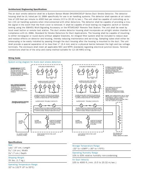
Architectural/Engineering Specifications<br />
The air duct smoke detector shall be a System Sensor Model DH100ACDCLP Series <strong>Duct</strong> <strong>Smoke</strong> <strong>Detector</strong>. The detector<br />
housing shall be UL listed per UL 268A specifically for use in air handling systems. The detector shall operate at air velocities<br />
of 100 feet per minute to 4000 feet per minute (0.5 to 20.32 m/sec.). The unit shall be capable of controlling up to<br />
ten (10) air handling systems when interconnected with other detectors. The detector shall be capable of providing a trouble<br />
signal in the event that the front cover is removed. It shall be capable of local testing via magnetic switch or remote<br />
testing using the SSK451 Multi-Signaling Accessory or the RTS451KEY Remote Test Station. The unit shall be reset by<br />
local reset button or remote test station. The duct smoke detector housing shall incorporate an airtight smoke chamber in<br />
compliance with UL 268A, Standard for <strong>Smoke</strong> <strong>Detector</strong>s for <strong>Duct</strong> Applications. The housing shall be capable of mounting<br />
to either rectangular or round ducts without adapter brackets. An integral filter system shall be included to reduce dust<br />
and residue effects on detector and housing, thereby reducing maintenance and servicing. Sampling tubes shall either be<br />
telescoping or be easily installed by passing through the duct housing after the housing is mounted to the duct. The unit<br />
shall provide a spacial separation of no less than 1 ⁄4″ (6.4 mm) and/or a physical barrier between the high and low voltage<br />
terminals. The enclosure shall meet all applicable NEC and NFPA standards regarding electrical junction boxes. Terminal<br />
connections shall be of the strip and clamp method suitable for 12–18 AWG wiring.<br />
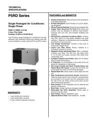
Wiring Guide<br />
System wiring diagram for 4-wire duct smoke detectors<br />
POWER INPUTS ACCEPT<br />
24 VDC, 24 VAC 50-60 HZ,<br />
120 VAC 50-60 HZ, OR<br />
220/240 VAC 50-60 HZ.<br />
CONNECT POWER SOURCE<br />
TO APPROPRIATE TERMINALS<br />
OF EACH DETECTOR.<br />
AVAILABLE POWER INPUTS<br />
9 10 A B C<br />
24V<br />
120<br />
VAC<br />
220/240<br />
VAC<br />
AVAILABLE POWER INPUTS<br />
9 10 A B C<br />
24V<br />
120<br />
VAC<br />
220/240<br />
VAC<br />
CONNECT POWER SOURCE<br />
TO APPROPRIATE TERMINALS<br />
OF EACH DETECTOR. SEE<br />
SPECIFICATIONS FOR<br />
ADDITIONAL POWER SUPPLY<br />
INFORMATION.<br />
AUX. CONTACT RATINGS<br />
10A @ 30 VDC RESISTIVE<br />
10A @ 250 VAC<br />
100mA MINIMUM @ 5 VDC<br />
NOT INTENDED FOR<br />
CONNECTION TO CONTROL<br />
PANELS.<br />
N.C.<br />
ALARM AUXILIARY CONTACTS<br />
FOR FAN SHUTDOWN, ETC.<br />
16 6 17 7 18 8<br />
C.<br />
N.O.<br />
N.O.<br />
C.<br />
N.C.<br />
N.C.<br />
ALARM AUXILIARY CONTACTS<br />
FOR FAN SHUTDOWN, ETC.<br />
16 6 17 7 18 8<br />
C.<br />
N.O.<br />
N.O.<br />
C.<br />
N.C.<br />
FOR WIRING OF AUXILIARY<br />
DEVICES, REFER TO<br />
MANUFACTURER’S<br />
INSTALLATION INSTRUCTIONS<br />
OR CONTACT MANUFACTURER.<br />
TROUBLE CONTACT RATING<br />
2.0 A @ 30 VDC resistive<br />
ALARM AUXILIARY CONTACTS SHOWN IN<br />
STANDBY. CONTACTS TRANSFER DURING<br />
ALARM AS INDICATED BY THE ARROWS.<br />
SUPERVISORY TROUBLE CONTACTS<br />
ALARM AUXILIARY CONTACTS SHOWN IN<br />
STANDBY. CONTACTS TRANSFER DURING<br />
ALARM AS INDICATED BY THE ARROWS.<br />
SUPERVISORY TROUBLE CONTACTS<br />
14 3 14<br />
3<br />
NOTE: THE SUPERVISORY RELAY NOW<br />
PROVIDES A "FORM C" CONTACT FOR<br />
CUSTOMIZED APPLICATIONS.<br />
FOR STANDARD APPLICATIONS, ONLY<br />
THE "NO" CONTACT IS USED<br />
+<br />
TROUBLE CONTACTS CLOSED IN ALARM AND STANDBY.<br />
CONTACTS OPEN WHILE DETECTOR PCB OR POWER IS<br />
REMOVED OR WHEN TAMPER FEATURE TIMES OUT. OPEN<br />
CONTACTS SIGNAL TROUBLE CONDITION TO PANEL.<br />
TROUBLE CONTACTS CLOSED IN ALARM AND STANDBY.<br />
CONTACTS OPEN WHILE DETECTOR PCB OR POWER IS<br />
REMOVED OR WHEN TAMPER FEATURE TIMES OUT. OPEN<br />
CONTACTS SIGNAL TROUBLE CONDITION TO PANEL.<br />
5<br />
5<br />
ALARM<br />
INITIATION<br />
LOOP<br />
—<br />
ALARM<br />
INITIATION<br />
CONTACTS<br />
4<br />
CONTACTS SHOWN<br />
OPEN IN STANDBY.<br />
CONTACTS CLOSE<br />
IN ALARM.<br />
ALARM<br />
INITIATION<br />
CONTACTS<br />
4<br />
CONTACTS SHOWN<br />
OPEN IN STANDBY.<br />
CONTACTS CLOSE<br />
IN ALARM.<br />
UL LISTED 4-WIRE<br />
CONTROL PANEL<br />
FIRST DETECTOR IN THE LOOP<br />
DH100ACDC<br />
LAST DETECTOR IN THE LOOP<br />
DH100ACDC<br />
EOL RESISTOR<br />
SPECIFIED BY<br />
PANEL MANUFACTURER<br />
Specifications<br />
Size<br />
14 3 ⁄8″ (37 cm.) Length<br />
5 1 ⁄2″ (14 cm.) Width<br />
2 3 ⁄4″ (7 cm.) Depth<br />
Shipping Weight<br />
3 3 ⁄4 lbs. (1.7 kg.)<br />
Operating Temperature Range<br />
32° to 131°F (0° to 55°C)<br />
Storage Temperature Range<br />
–22° to +158°F (–30° to +70°C)<br />
Operating Humidity Range<br />
10% to 93% relative humidity non-condensing<br />
Air <strong>Duct</strong> Velocity<br />
100 to 4000 ft./min. (0.5 to 20.32 m/sec.)