4-Wire Low-Flow Duct Smoke Detector - Nordyne
4-Wire Low-Flow Duct Smoke Detector - Nordyne
4-Wire Low-Flow Duct Smoke Detector - Nordyne

You also want an ePaper? Increase the reach of your titles
YUMPU automatically turns print PDFs into web optimized ePapers that Google loves.
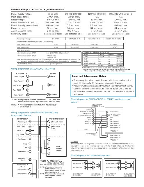
Electrical Ratings – DH100ACDCLP (Includes <strong>Detector</strong>)<br />
Power supply voltage: 20-29 VDC 24 VAC 50-60-Hz 120 VAC 50-60 Hz 220/240 VAC 50-60 Hz<br />
Input capacitance: 270 µF max. 270 µF max. N/A N/A<br />
Reset voltage: 3.0 VDC min. 2.0 VAC min. 10 VAC min. 20 VAC min.<br />
Reset time (with RTS451): .03 to 0.3 sec. .03 to 0.3 sec. .03 to 0.3 sec. .03 to 0.3 sec.<br />
Reset time (by power down): 0.6 sec. max. 0.6 sec. max. 0.6 sec. max. 0.6 sec. max.<br />
Power up time: 34 sec. max. 34 sec. max. 34 sec. max. 34 sec. max.<br />
Alarm response time: 2 to 17 sec. 2 to 17 sec. 2 to 17 sec. 2 to 17 sec.<br />
Sensitivity Test: See detector label See detector label See detector label See detector label<br />
Power Supply Voltage 20 - 29 VDC 24 VAC 50 - 60 Hz 120 VAC 50 - 60 Hz 220/240 VAC 50 - 60 Hz<br />
CURRENT REQUIREMENTS (USING NO ACCESSORIES)<br />
Max. standby current 15 mA 35 mA RMS 25 mA RMS* 15 mA RMS*<br />
Max. alarm current 70 mA 125 mA RMS 35 mA RMS* 25 mA RMS*<br />
CONTACT RATINGS<br />
Alarm initiation contacts (SPST)<br />
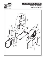
Wiring diagram for DH100ACDCLP to APA451<br />
2.0A @ 30 VAC/DC (0.6 power factor)<br />
Alarm auxiliary contacts (DPDT)<br />
10A @ 30 VDC<br />
10A @ 250 VAC<br />
Note: Alarm auxiliary contacts must switch 100mA minimum at 5VDC. Alarm auxiliary contacts shall not be<br />
connected to inititaing circuits of control panels. Use the alarm initiation contact for this purpose.<br />
Trouble contacts (SPDT)<br />
DH100ACDCLP<br />
Alarm Signal<br />
Aux. Power +<br />
Sup. N. O.<br />
Sup. COM<br />
Aux. Power –<br />
15<br />
19<br />
14<br />
3<br />
20 1<br />
2.0A @ 30 VDC (resistive)<br />
2<br />
3<br />
APA451<br />
Alarm<br />
Power<br />
Common<br />
ACCESSORY CURRENT LOADS AT 24 VDC<br />
DEVICE<br />
APA451<br />
PA400<br />
RA400Z<br />
RTS451/RTS451KEY<br />
SSK451<br />
STANDBY<br />
12.5mA Max.<br />
0mA<br />
0mA<br />
12mA*<br />
5mA Max.<br />
TROUBLE<br />
n/a<br />
n/a<br />
n/a<br />
n/a<br />
9mA Max.<br />
ALARM<br />
30mA Max.<br />
15mA Max.<br />
10mA Max.<br />
7.5mA Max.<br />
30mA Max.<br />
*NOTE: When a unit is powered at the 120VAC or 220/240VAC input, any<br />
combination of accessories may be used such that the given accessory loads are:<br />
60 mA or less in the standby state; 110 mA or less in the alarm state.<br />
Important Interconnect Notes<br />
• When using the interconnect feature, all interconnected units<br />
must be powered with the same, independent supply.<br />
• Polarity must be maintained throughout the interconnect wiring.<br />
Connect terminal 12 on unit 1 to terminal 12 on unit 2 and so<br />
on. Similarly, connect terminal 1 on unit 1 to terminal 1 on unit 2<br />
and so on.<br />
NOTE:<br />
NOTE:<br />
Wiring diagram shown is for DH100ACDCLP 4-wire duct<br />
smoke detector system equipped without a control panel.<br />
A trouble condition is indicated when the green LED<br />
is not illuminated.<br />
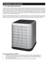
Wiring diagram for DH100ACDCLP to SSK451 and interconnect<br />
feature<br />
FIELD INSTALLED<br />
JUMPER FOR<br />
TEMPORAL PATTERN<br />
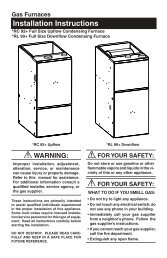
Wiring diagram for the RTS451/RTS451KEY and<br />
interconnect feature<br />
DH100ACDCLP<br />
Alarm Signal<br />
Aux. Power +<br />
Sup. N. O.<br />
Sup. COM<br />
Aux. Power —<br />
Reset<br />
Test<br />
Interconnect —<br />
Interconnect +<br />
Unit 1<br />
DH100ACDCLP<br />
UNIT 2<br />
Interconnect —<br />
Interconnect +<br />
15<br />
19<br />
14<br />
3<br />
20<br />
2<br />
11<br />
1<br />
12<br />
1<br />
12<br />
1<br />
6<br />
2<br />
3<br />
4<br />
5<br />
RTS451/RTS451KEY<br />
(Red LED) Alarm<br />
(Green LED)<br />
Power<br />
Field<br />
Installed<br />
Jumper<br />
* NOTE: For RTS451KEY only<br />
without a Control Panel.<br />
RTS451 does not have a terminal 6.<br />
NOTE: Wiring diagram shown is for<br />
DH100ACDCLP 4-wire duct<br />
smoke detector system equipped<br />
without a control panel.<br />
NOTE: A trouble condition is indicated<br />
when the green LED is not<br />
illuminated.<br />
*<br />
COMMON 3<br />
TEMPORAL SELECT 2<br />
ALARM SIGNAL 1<br />
SUPERVISORY SIGNAL 4<br />
RESET 7<br />
TEST 8<br />
POWER (–) 6<br />
POWER (+) 5<br />
SSK451<br />
FIELD INSTALLED<br />
JUMPER<br />
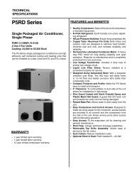
Wiring diagrams for optional accessories<br />
ALARM SIGNAL (+)<br />
AUX POWER (—)<br />
DUCT DETECTOR<br />
DH100ACDCLP<br />
15<br />
20<br />
(+)<br />
(—)<br />
PA400 (OPTIONAL)<br />
AUDIBLE ALERT<br />
15 ALARM SIGNAL<br />
3<br />
SUPERVISORY<br />
NO<br />
14 CONTACT<br />
2 RESET<br />
11 TEST<br />
20 AUX. POWER (–)<br />
19 AUX. POWER (+)<br />
12 INTERCONNECT +<br />
1 INTERCONNECT –<br />
DH100ACDCLP<br />
UNIT 1<br />
12 INTERCONNECT +<br />
1 INTERCONNECT –<br />
DH100ACDCLP<br />
UNIT 2<br />
Coil Note:<br />
Please note that the magnetic coil supplied with the RTS451/RTS451KEY is not<br />
required when these accessories are used with the DH100 detectors. The functionality<br />
of the magnetic coil has been designed into the circuitry of the Innovair duct<br />
smoke detectors.<br />
ALARM SIGNAL (+)<br />
AUX POWER (—)<br />
DUCT DETECTOR<br />
DH100ACDCLP<br />
15<br />
20<br />
(+)<br />
(—)<br />
RED<br />
RA400Z (OPTIONAL)<br />
REMOTE (LED)<br />
ANNUNCIATOR