Troubleshooting and Diagnostics EntraGuard ... - Keri Systems
Troubleshooting and Diagnostics EntraGuard ... - Keri Systems
Troubleshooting and Diagnostics EntraGuard ... - Keri Systems

Create successful ePaper yourself
Turn your PDF publications into a flip-book with our unique Google optimized e-Paper software.
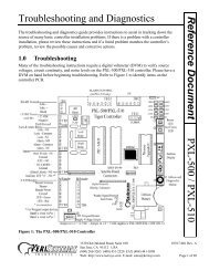
<strong>Troubleshooting</strong> <strong>and</strong> <strong>Diagnostics</strong><br />
The <strong>Troubleshooting</strong> <strong>and</strong> <strong>Diagnostics</strong> Reference Document provides instructions to assist in<br />
tracking down the source of many basic controller installation problems. If there is a problem with a<br />
controller installation, please review these instructions <strong>and</strong> if a listed problem matches the<br />
controller’s problem, review the possible causes <strong>and</strong> corrective actions.<br />
1.0 <strong>Troubleshooting</strong><br />
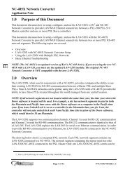
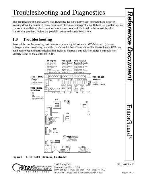
Some of the troubleshooting instructions require a digital voltmeter (DVM) to verify source<br />
voltages, circuit continuity, <strong>and</strong> noise levels on the <strong>EntraGuard</strong> controller. Please have a DVM on<br />
h<strong>and</strong> before beginning troubleshooting. Refer to Figures 1 through 4 on pages 1 through 4 to<br />
identify items on the controller PCBs.<br />
Reference Document<br />
<strong>EntraGuard</strong> ®<br />
Figure 1: The EG-5000 (Platinum) Controller<br />
2305 Bering Drive 01912-001 Rev. F<br />
San Jose, CA 95131 USA<br />
(800) 260-5265 (408) 435-8400 FAX (408) 577-1792<br />
Web: www.kerisys.com E-mail: sales@kerisys.com Page 1 of 23
Reference Document<br />
<strong>Troubleshooting</strong> <strong>and</strong> <strong>Diagnostics</strong><br />
<strong>EntraGuard</strong> ®<br />
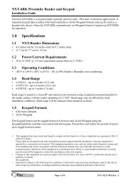
Figure 2: The EG-750 (Gold 1 , Titanium, <strong>and</strong> Silver) Controller<br />
1. For <strong>EntraGuard</strong> Gold controllers with the mechanical (st<strong>and</strong>ard) keypad with part numbers 05720-001,<br />
05720-002, <strong>and</strong> 05721-001.<br />
2305 Bering Drive 01912-001 Rev. F<br />
San Jose, CA 95131 USA<br />
(800) 260-5265 (408) 435-8400 FAX (408) 577-1792<br />
Web: www.kerisys.com E-mail: sales@kerisys.com Page 2 of 23
<strong>Troubleshooting</strong> <strong>and</strong> <strong>Diagnostics</strong><br />
Reference Document<br />
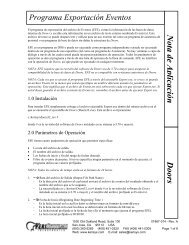
Figure 3: The <strong>EntraGuard</strong> Gold Main Board 1<br />
<strong>EntraGuard</strong> ®<br />
1. For all <strong>EntraGuard</strong> Gold controllers with the alpha numeric keypad <strong>and</strong> <strong>EntraGuard</strong> Gold controllers with<br />
the mechanical (st<strong>and</strong>ard) keypad with part numbers 05712-001, 05712-002, <strong>and</strong> 05713-001.<br />
2305 Bering Drive 01912-001 Rev. F<br />
San Jose, CA 95131 USA<br />
(800) 260-5265 (408) 435-8400 FAX (408) 577-1792<br />
Web: www.kerisys.com E-mail: sales@kerisys.com Page 3 of 23
Reference Document<br />
<strong>Troubleshooting</strong> <strong>and</strong> <strong>Diagnostics</strong><br />
<strong>EntraGuard</strong> ®<br />
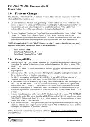
Figure 4: The <strong>EntraGuard</strong> Gold Voice Channel <strong>and</strong> I/O Board 1<br />
1. For all <strong>EntraGuard</strong> Gold controllers with the alpha numeric keypad <strong>and</strong> <strong>EntraGuard</strong> Gold controllers with<br />
the mechanical (st<strong>and</strong>ard) keypad with part numbers 05712-001, 05712-002, <strong>and</strong> 05713-001.<br />
2305 Bering Drive 01912-001 Rev. F<br />
San Jose, CA 95131 USA<br />
(800) 260-5265 (408) 435-8400 FAX (408) 577-1792<br />
Web: www.kerisys.com E-mail: sales@kerisys.com Page 4 of 23
<strong>Troubleshooting</strong> <strong>and</strong> <strong>Diagnostics</strong><br />
Some Corrective Action requires looking at the instructions in the appropriate Quick Start Guide.<br />
Here are the available guides along with the part number:<br />
<strong>EntraGuard</strong> Platinum Quick Start Guide - P/N 01969-001<br />
<strong>EntraGuard</strong> Silver Quick Start Guide - P/N 01960-001<br />
<strong>EntraGuard</strong> Titanium Quick Start Guide - P/N 01962-001<br />
<strong>EntraGuard</strong> Gold Quick Start Guide - P/N 01801-001<br />
NOTE: All references to the <strong>EntraGuard</strong> Gold controller throughout the remainder of this document<br />
are to those with the alpha numeric keypad or mechanical (st<strong>and</strong>ard) keypad with part numbers<br />
05712-001, 05712-002, or 05713-001. For <strong>EntraGuard</strong> Gold controllers with the mechanical<br />
(st<strong>and</strong>ard) keypad <strong>and</strong> part numbers 05720-001, 05720-001, or 05721-001, refer to the EG-750.<br />
Problem Possible Cause Corrective Action<br />
The Doors<br />
software cannot<br />
be installed on the<br />
host computer.<br />
1. The host computer does<br />
not have a Pentium<br />
microprocessor.<br />
2. The host computer does<br />
not have enough RAM<br />
memory.<br />
3. The host computer does<br />
not have enough hard disk<br />
space.<br />
4. The host computer’s video<br />
card/monitor resolution is<br />
too low.<br />
5. The host computer is<br />
running an operating<br />
system incompatible with<br />
the Doors software.<br />
6. The host computer does<br />
not have a compatible<br />
operating system installed.<br />
• Verify the host computer meets the<br />
minimum requirements specified in<br />
the Doors Users Guide (P/N 01914-<br />
100).<br />
Reference Document<br />
<strong>EntraGuard</strong> ®<br />
2305 Bering Drive 01912-001 Rev. F<br />
San Jose, CA 95131 USA<br />
(800) 260-5265 (408) 435-8400 FAX (408) 577-1792<br />
Web: www.kerisys.com E-mail: sales@kerisys.com Page 5 of 23
Reference Document<br />
<strong>EntraGuard</strong> ®<br />
<strong>Troubleshooting</strong> <strong>and</strong> <strong>Diagnostics</strong><br />
Problem Possible Cause Corrective Action<br />
The controller<br />
does not powerup<br />
(the LCD is<br />
blank <strong>and</strong> the<br />
keypad is not<br />
illuminated).<br />
The controller<br />
cannot<br />
communicate<br />
with the Doors<br />
access control<br />
program.<br />
1. No power or insufficient<br />
power has been supplied to<br />
the system.<br />
1. Verify data is being<br />
transferred to <strong>and</strong> from the<br />
controller (see “Corrective<br />
Action” column).<br />
2. The communication cable<br />
is loose or unplugged.<br />
• Check the main power circuit breaker.<br />
• Verify the positive power lead is on<br />
TB-2, pin 1 <strong>and</strong> the negative power<br />
lead is on TB-2, pin 2<br />
• Measure the input voltage across pin 1<br />
(positive) <strong>and</strong> pin 2 (negative) of TB-<br />
2. The voltage should read between 12<br />
<strong>and</strong> 14 VDC.<br />
• Disconnect the power supply from the<br />
controller <strong>and</strong> verify the supply’s<br />
voltage. The voltage should read<br />
between 12 <strong>and</strong> 14 VDC.<br />
• Verify there is a proper earth ground.<br />
• EG-5000/EG-750 controller - On the<br />
controller (next to TB12) is a set of<br />
communication LEDs (see Figure 1 on<br />
page 1 <strong>and</strong> Figure 2 on page 2).<br />
Initiate a data transfer comm<strong>and</strong> <strong>and</strong><br />
view the TXD, DTR, <strong>and</strong> RXD LEDs.<br />
These LEDs should flicker if data is<br />
being transferred to <strong>and</strong> from the<br />
controller.<br />
• Gold controller - On the right side of<br />
the controller’s main board is a set of<br />
communication LEDs (see Figure 4 on<br />
page 4). Initiate a data transfer<br />
comm<strong>and</strong> <strong>and</strong> view the Tx+, Tx-,<br />
DTR, <strong>and</strong> CTS LEDs. These LEDs<br />
should flicker if data is being<br />
transferred to <strong>and</strong> from the controller.<br />
• Verify the communication cable is<br />
plugged in correctly.<br />
2305 Bering Drive 01912-001 Rev. F<br />
San Jose, CA 95131 USA<br />
(800) 260-5265 (408) 435-8400 FAX (408) 577-1792<br />
Web: www.kerisys.com E-mail: sales@kerisys.com Page 6 of 23
<strong>Troubleshooting</strong> <strong>and</strong> <strong>Diagnostics</strong><br />
Problem Possible Cause Corrective Action<br />
3. The J11 (EG-5000/EG-<br />
750) or JP3 (Gold)<br />
INT_MODEM jumper is<br />
not set correctly.<br />
4. The modem type in use is<br />
incompatible.<br />
5. The controller to PC directconnect<br />
cable is not wired<br />
correctly.<br />
6. Doors is not configured to<br />
communicate through the<br />
proper COM port.<br />
7. The communication cable<br />
is connected to the wrong<br />
COM port.<br />
8. The communication cable<br />
is connected to the wrong<br />
controller.<br />
9. The master controller is a<br />
PXL-250.<br />
• Verify the INT_MODEM jumper is set<br />
correctly for the chosen mode of<br />
communication.<br />
- If you are using the phone port for<br />
communication, the jumper should<br />
be set ON J11/JP3.<br />
- If you are using the RS-232 port<br />
for communication, the jumper<br />
should NOT be on J11/JP3.<br />
• Refer to the modem’s manual <strong>and</strong><br />
verify the modem is Hayes<br />
compatible, communicates at 9600<br />
baud or greater, can be configured to<br />
turn error checking off, <strong>and</strong> has<br />
nonvolatile RAM backup.<br />
• If the installation uses a <strong>Keri</strong> <strong>Systems</strong><br />
cable, verify the correct cable has been<br />
installed.<br />
• If the installation uses a self-made<br />
cable, refer to the instructions in the<br />
appropriate Quick Start Guide <strong>and</strong><br />
verify the cable has been wired<br />
correctly.<br />
• Refer to the Doors Users Guide (P/N<br />
01914-100) or online help for COM<br />
port configuration instructions.<br />
• Run COMTEST to verify basic COM<br />
port operation.<br />
• Verify the communication cable is<br />
connected to the correct COM port.<br />
• Verify the communication cable is<br />
connected to the master controller in<br />
the access control network.<br />
• Verify the master controller is not a<br />
PXL-250.<br />
Reference Document<br />
<strong>EntraGuard</strong> ®<br />
2305 Bering Drive 01912-001 Rev. F<br />
San Jose, CA 95131 USA<br />
(800) 260-5265 (408) 435-8400 FAX (408) 577-1792<br />
Web: www.kerisys.com E-mail: sales@kerisys.com Page 7 of 23
Reference Document<br />
<strong>EntraGuard</strong> ®<br />
<strong>Troubleshooting</strong> <strong>and</strong> <strong>Diagnostics</strong><br />
Problem Possible Cause Corrective Action<br />
The <strong>EntraGuard</strong>’s<br />
internal modem<br />
will not<br />
communicate.<br />
10. The master controller is not<br />
set with address 1.<br />
11. The Doors program is<br />
connected to the wrong site<br />
(if the software is<br />
configured for multi-site<br />
mode).<br />
12. The wrong PIN has been<br />
entered (if the software is<br />
configured to use the PIN<br />
security feature).<br />
13. The controller’s firmware<br />
<strong>and</strong> the Doors software are<br />
not compatible.<br />
14. The host computer’s serial<br />
port has an incompatible<br />
UART.<br />
• Verify the master controller’s address<br />
is 1.<br />
• In the Doors program, click on the<br />
Select Site button <strong>and</strong> verify the<br />
correct site has been selected.<br />
• In the Doors program, verify the PIN<br />
is correct in the Setup > System ><br />
Sites menu option.<br />
• The firmware found in older<br />
controllers is not compatible with<br />
Doors software. Contact your <strong>Keri</strong><br />
Dealer to verify firmware/software<br />
compatibility.<br />
• The serial port must have a 16550<br />
UART. Consult a computer technician<br />
to resolve this problem.<br />
15. There is an IRQ conflict. • Consult a computer technician to<br />
resolve this problem.<br />
16. The COM port is not<br />
working.<br />
1. The J11 (EG-5000/<br />
EG-750) or JP3 (Gold)<br />
INT_MODEM jumper is<br />
not set correctly.<br />
• Consult a computer technician to<br />
resolve this problem.<br />
• Verify the jumper is set ON J11/JP3<br />
INT_MODEM for use with the<br />
internal modem.<br />
2305 Bering Drive 01912-001 Rev. F<br />
San Jose, CA 95131 USA<br />
(800) 260-5265 (408) 435-8400 FAX (408) 577-1792<br />
Web: www.kerisys.com E-mail: sales@kerisys.com Page 8 of 23
<strong>Troubleshooting</strong> <strong>and</strong> <strong>Diagnostics</strong><br />
Problem Possible Cause Corrective Action<br />
The controller<br />
will not<br />
communicate<br />
with the modem<br />
(if using an<br />
external modem).<br />
1. Verify data is being<br />
transferred to <strong>and</strong> from the<br />
controller (see “Corrective<br />
Action” column).<br />
• EG-5000/EG-750 controller - On the<br />
controller (next to TB12) is a set of<br />
communication LEDs (see Figure 1 on<br />
page 1 <strong>and</strong> Figure 2 on page 2).<br />
Initiate a data transfer comm<strong>and</strong> <strong>and</strong><br />
view the TXD, DTR, <strong>and</strong> RXD LEDs.<br />
These LEDs should flicker if data is<br />
being transferred to <strong>and</strong> from the<br />
controller.<br />
• Gold controller - On the right side of<br />
the controller’s main board is a set of<br />
communication LEDs (see Figure 4 on<br />
page 4). Initiate a data transfer<br />
comm<strong>and</strong> <strong>and</strong> view the Tx+, Tx-,<br />
DTR, <strong>and</strong> CTS LEDs. These LEDs<br />
should flicker if data is being<br />
transferred to <strong>and</strong> from the controller.<br />
2. The modem is turned off. • Verify the modem’s power is on.<br />
3. The modem was plugged<br />
into an already active<br />
controller.<br />
4. The controller to modem<br />
cable is not correct.<br />
5. The modem type in use is<br />
incompatible.<br />
• Turn the power off to both the<br />
controller <strong>and</strong> modem. Power the<br />
modem on <strong>and</strong> then the controller.<br />
• If the installation uses a <strong>Keri</strong> <strong>Systems</strong><br />
cable, verify the correct cable has been<br />
installed.<br />
• If the installation uses a self-made<br />
cable, refer to the instructions<br />
provided in the appropriate Quick<br />
Start Guide to verify the cable has<br />
been wired correctly.<br />
• Refer to the modem’s manual <strong>and</strong><br />
verify the modem is Hayes<br />
compatible, communicates at 9600<br />
baud or greater, can be configured to<br />
turn error checking off, <strong>and</strong> has<br />
nonvolatile RAM backup.<br />
Reference Document<br />
<strong>EntraGuard</strong> ®<br />
2305 Bering Drive 01912-001 Rev. F<br />
San Jose, CA 95131 USA<br />
(800) 260-5265 (408) 435-8400 FAX (408) 577-1792<br />
Web: www.kerisys.com E-mail: sales@kerisys.com Page 9 of 23
Reference Document<br />
<strong>EntraGuard</strong> ®<br />
<strong>Troubleshooting</strong> <strong>and</strong> <strong>Diagnostics</strong><br />
Problem Possible Cause Corrective Action<br />
The host PC will<br />
not communicate<br />
with the modem.<br />
6. The modem cable is<br />
connected to the wrong<br />
controller.<br />
7. The J11 (EG-5000/<br />
EG-750) or JP3 (Gold)<br />
INT_MODEM jumper is<br />
not set correctly.<br />
8. The master controller is a<br />
PXL-250.<br />
9. The master controller is not<br />
set with address 1.<br />
10. The Doors program is<br />
connected to the wrong site<br />
(if the software is<br />
configured for multi-site<br />
mode).<br />
11. The wrong PIN has been<br />
entered (if the software is<br />
configured to use the PIN<br />
security feature).<br />
• Verify the modem cable is connected<br />
to the master controller in the access<br />
control network.<br />
• Verify the jumper is NOT on J11/JP3<br />
INT_MODEM when using an external<br />
modem.<br />
• Verify the master controller is not a<br />
PXL-250.<br />
• Verify the master controller’s address<br />
is 1.<br />
• In the Doors program, click on the<br />
Select Site button <strong>and</strong> verify the<br />
correct site has been selected.<br />
• In the Doors program, verify the PIN<br />
is correct in the Setup > System ><br />
Sites menu option.<br />
1. The modem is turned off. • Verify the modem’s power is on.<br />
2. The wrong COM port has<br />
been selected in the Doors<br />
program.<br />
3. The modem is the wrong<br />
type.<br />
• In the Doors program, verify the<br />
correct COM port has been selected in<br />
the Setup > System > Network<br />
Configuration menu option.<br />
• Refer to the modem’s manual <strong>and</strong><br />
verify the modem is Hayes<br />
compatible, communicates at 9600<br />
baud or greater, can be configured to<br />
turn error checking off, <strong>and</strong> has<br />
nonvolatile RAM backup.<br />
2305 Bering Drive 01912-001 Rev. F<br />
San Jose, CA 95131 USA<br />
(800) 260-5265 (408) 435-8400 FAX (408) 577-1792<br />
Web: www.kerisys.com E-mail: sales@kerisys.com Page 10 of 23
<strong>Troubleshooting</strong> <strong>and</strong> <strong>Diagnostics</strong><br />
Problem Possible Cause Corrective Action<br />
The lock relay<br />
continually cycles<br />
on <strong>and</strong> off.<br />
The Doors<br />
program will not<br />
run.<br />
Some controllers<br />
on the access<br />
control network<br />
are not<br />
communicating<br />
with the Doors<br />
program.<br />
4. The host PC to modem<br />
cable is not correct.<br />
5. The host computer’s serial<br />
port has an incompatible<br />
UART.<br />
• If the installation uses a <strong>Keri</strong> <strong>Systems</strong><br />
cable, verify the correct cable has been<br />
installed.<br />
• If the installation uses a self-made<br />
cable, refer to the instructions<br />
provided in the appropriate Quick<br />
Start Guide to verify the cable has<br />
been wired correctly.<br />
• The serial port must have a 16550<br />
UART. Consult a computer technician<br />
to resolve this problem.<br />
6. There is an IRQ conflict. • Consult a computer technician to<br />
resolve this problem.<br />
7. The COM port is not<br />
working.<br />
1. The firmware PROM is not<br />
seated properly.<br />
1. The host PC does not have<br />
enough conventional<br />
memory available for the<br />
program.<br />
1. There is an addressing<br />
conflict between the<br />
controllers.<br />
• Consult a computer technician to<br />
resolve this problem.<br />
• Turn controller power off. Locate the<br />
firmware PROM, <strong>and</strong> ensure the<br />
PROM is seated properly in its socket<br />
on the main board. Now follow the<br />
instructions provided in the<br />
appropriate Quick Start Guide to reset<br />
the controller’s RAM.<br />
• The host PC must have at least 560K<br />
of conventional memory available for<br />
use by the Doors program. Consult a<br />
computer technician to resolve this<br />
problem.<br />
• Check the address on each controller<br />
on the network. Each controller must<br />
have a unique address. The master<br />
controller must be set to 1 (<strong>and</strong> NOT<br />
be a PXL-250).<br />
Reference Document<br />
<strong>EntraGuard</strong> ®<br />
2305 Bering Drive 01912-001 Rev. F<br />
San Jose, CA 95131 USA<br />
(800) 260-5265 (408) 435-8400 FAX (408) 577-1792<br />
Web: www.kerisys.com E-mail: sales@kerisys.com Page 11 of 23
Reference Document<br />
<strong>EntraGuard</strong> ®<br />
<strong>Troubleshooting</strong> <strong>and</strong> <strong>Diagnostics</strong><br />
Problem Possible Cause Corrective Action<br />
User name not<br />
showing in<br />
directory list on<br />
<strong>EntraGuard</strong> LCD<br />
2. RAM is corrupted in one or<br />
more of the controllers.<br />
3. The access control network<br />
is not wired correctly.<br />
4. Controllers are not<br />
powered on.<br />
5. No power or insufficient<br />
power has been supplied to<br />
the system.<br />
1. User ID not enrolled as an<br />
<strong>EntraGuard</strong> ID.<br />
• In the Doors program, click on Setup<br />
> System > Controller Status menu<br />
option. Select each controller, one-ata-time,<br />
<strong>and</strong> click on the Status button.<br />
Note those controllers that do not<br />
respond or that respond incorrectly.<br />
These controllers must have their<br />
RAM reset. Follow the instructions<br />
provided in the appropriate Quick<br />
Start Guide to reset the controller’s<br />
RAM.<br />
• Review the access control network<br />
wiring on each controller. Verify the<br />
network wiring is connected correctly.<br />
• Verify all connections have been made<br />
on lead wire <strong>and</strong> not on wire<br />
insulation.<br />
• Verify all controllers are powered on.<br />
• Check the main power circuit breaker.<br />
• Verify the positive power lead is on<br />
TB-2, pin 1 <strong>and</strong> the negative power<br />
lead is on TB-2, pin 2.<br />
• Measure the input voltage across pin 1<br />
(positive) <strong>and</strong> pin 2 (negative) of TB-<br />
2. The voltage should read between 12<br />
<strong>and</strong> 14 VDC.<br />
• Disconnect the power supply from the<br />
controller <strong>and</strong> verify the supply’s<br />
voltage. The voltage should read<br />
between 12 <strong>and</strong> 14 VDC.<br />
• Verify there is a proper earth ground.<br />
• Make sure the <strong>EntraGuard</strong> ID option is<br />
selected when enrolling User IDs in<br />
Doors. See the Doors Users Guide<br />
(P/N 01914-100) for how to enroll<br />
User IDs.<br />
2305 Bering Drive 01912-001 Rev. F<br />
San Jose, CA 95131 USA<br />
(800) 260-5265 (408) 435-8400 FAX (408) 577-1792<br />
Web: www.kerisys.com E-mail: sales@kerisys.com Page 12 of 23
<strong>Troubleshooting</strong> <strong>and</strong> <strong>Diagnostics</strong><br />
Problem Possible Cause Corrective Action<br />
User ID denied<br />
access<br />
2. User ID not turned ON. • In Doors, verify the ON/OFF cell is<br />
set to ON in the Setup Cards window.<br />
3. No access group assigned. • In Doors, verify a valid Access Group<br />
has been assigned in the Setup Cards<br />
window.<br />
4. No phone number listed. • In Doors, verify the correct phone<br />
number has been entered for each user<br />
(including any necessary area codes)<br />
in the Setup Cards window.<br />
5. Name displayed disabled. • In Doors, verify the Name Displayed<br />
cell is set to ON in the Setup Cards<br />
window.<br />
1. User ID not enrolled as an<br />
<strong>EntraGuard</strong> ID<br />
• Make sure the <strong>EntraGuard</strong> ID option is<br />
selected when enrolling User IDs in<br />
Doors. See the Doors Users Guide<br />
(P/N 01914-100) for how to enroll<br />
User IDs.<br />
2. User ID not turned ON. • In Doors, verify on the Setup Cards<br />
spreadsheet that the ON/OFF cell is<br />
set to ON.<br />
3. Not entering all numbers in<br />
the User ID.<br />
4. Wrong access rights<br />
assigned to user.<br />
5. Changes in Doors software<br />
not saved <strong>and</strong> updated in<br />
controller.<br />
• If the User ID number of digits (in the<br />
System Options window in Doors) is<br />
set for a specific number of digits (5<br />
for example), then 5 digits must be<br />
entered (including any leading 0s).<br />
• Verify the time zone <strong>and</strong> access group<br />
assigned to the user in the Doors<br />
software.<br />
• Verify all changes made in the Doors<br />
software has been saved, then perform<br />
an update on the controller <strong>and</strong>/or<br />
network.<br />
Reference Document<br />
<strong>EntraGuard</strong> ®<br />
2305 Bering Drive 01912-001 Rev. F<br />
San Jose, CA 95131 USA<br />
(800) 260-5265 (408) 435-8400 FAX (408) 577-1792<br />
Web: www.kerisys.com E-mail: sales@kerisys.com Page 13 of 23
Reference Document<br />
<strong>Troubleshooting</strong> <strong>and</strong> <strong>Diagnostics</strong><br />
Problem Possible Cause Corrective Action<br />
Telephone<br />
comm<strong>and</strong> does<br />
not perform<br />
function<br />
1. The function may not be<br />
turned on in the Doors<br />
software.<br />
2. No number was<br />
programmed for the<br />
function in the Doors<br />
software.<br />
3. Pressing wrong telephone<br />
key for comm<strong>and</strong>.<br />
• In Doors, verify in the System Options<br />
page that the telephone entry option is<br />
turned on <strong>and</strong> a number has been<br />
assigned for each function. Then<br />
verify you are selecting the correct<br />
number on the telephone.<br />
• In Doors, verify the telephone key<br />
assigned for the specific task on the<br />
System Options page is the correct<br />
number.<br />
<strong>EntraGuard</strong> ®<br />
2305 Bering Drive 01912-001 Rev. F<br />
San Jose, CA 95131 USA<br />
(800) 260-5265 (408) 435-8400 FAX (408) 577-1792<br />
Web: www.kerisys.com E-mail: sales@kerisys.com Page 14 of 23
<strong>Troubleshooting</strong> <strong>and</strong> <strong>Diagnostics</strong><br />
2.0 Set Microphone Volume<br />
The <strong>EntraGuard</strong> controller comes with the microphone gain set for proper operation. The Set<br />
Microphone Vol menu option is not used at this time.<br />
3.0 <strong>Diagnostics</strong><br />
Built into every <strong>EntraGuard</strong> controller is a set of diagnostic programs designed to assist in field<br />
verification of controller functions. To reach the diagnostic menu, power up the <strong>EntraGuard</strong> unit<br />
while pressing the SW1 button (EG-5000/EG-750) or S1 button (Gold). The Reset Menu will<br />
appear (see Figure 5).<br />
Reference Document<br />
Figure 5: Reset Menu<br />
Select 4 on the keypad <strong>and</strong> the <strong>Diagnostics</strong> Menu will appear (see Figure 6).<br />
Figure 6: <strong>Diagnostics</strong> Menu<br />
There are three diagnostic screens available, each of which is described in the following sections.<br />
• Input Levels<br />
• Output States<br />
• Net Activity<br />
<strong>EntraGuard</strong> ®<br />
The <strong>EntraGuard</strong> Gold with Alpha/Numeric Keypad has an additional diagnostic screen.<br />
• Keypad Signal<br />
2305 Bering Drive 01912-001 Rev. F<br />
San Jose, CA 95131 USA<br />
(800) 260-5265 (408) 435-8400 FAX (408) 577-1792<br />
Web: www.kerisys.com E-mail: sales@kerisys.com Page 15 of 23
Reference Document<br />
<strong>Troubleshooting</strong> <strong>and</strong> <strong>Diagnostics</strong><br />
3.1 Input Levels<br />
The Input Levels screen allows you to monitor the status of the inputs. From the <strong>Diagnostics</strong> Menu<br />
(see Figure 6 on page 15), select number 1 on the keypad to reach the Input Levels screen. The<br />
screen will appear on the LCD (see Figure 7).<br />
Figure 7: Input Levels Menu<br />
KPAD - indicates which Keypad characters are displayed. On the <strong>EntraGuard</strong> Gold controller with<br />
Alpha/Numeric Keypad this is selected by using the JP2 KP_Select jumper.<br />
• A/N - both alpha <strong>and</strong> numeric characters are displayed<br />
• NUM - only numeric characters are displayed<br />
PGM - indicates which communication port is used for programming<br />
• INT - indicates the phone line port is being used (Master only)<br />
• EXT - indicates the RS-232 port is being used (Master only)<br />
• 485 - indicates the slave unit is using the 485 for communication<br />
<strong>EntraGuard</strong> ®<br />
PWR - indicates the voltage of the <strong>EntraGuard</strong> power supply.<br />
For the following inputs, 000 indicates a closed state <strong>and</strong> 255 indicates an open state.<br />
PSW - indicates the current state of the Postal Switch input<br />
DSW - indicates current state of the door input<br />
RTE - indicates current state of the RTE input<br />
AUX1 - indicates the current state of the AUX1 input<br />
AUX2 - indicates the current state of the AUX2 input<br />
2305 Bering Drive 01912-001 Rev. F<br />
San Jose, CA 95131 USA<br />
(800) 260-5265 (408) 435-8400 FAX (408) 577-1792<br />
Web: www.kerisys.com E-mail: sales@kerisys.com Page 16 of 23
<strong>Troubleshooting</strong> <strong>and</strong> <strong>Diagnostics</strong><br />
3.2 Output States<br />
The Output States screen allows you to monitor the status of the outputs. From the <strong>Diagnostics</strong><br />
Menu (see Figure 6 on page 15), select number 2 on the keypad to reach the Output States screen.<br />
The screen will appear on the LCD (see Figure 8).<br />
Figure 8: Output States<br />
Relay<br />
• K5 - Door Lock<br />
• K6 - Door Alarm<br />
• K7 - AUX 1<br />
• K8 - AUX 2<br />
Reference Document<br />
To change the state of one of the outputs, select the key on the <strong>EntraGuard</strong> Controller keypad that<br />
corresponds to the Activate Number of the output you want to change. The Current State will reflect<br />
the change <strong>and</strong> remain after exiting <strong>Diagnostics</strong>.<br />
<strong>EntraGuard</strong> ®<br />
2305 Bering Drive 01912-001 Rev. F<br />
San Jose, CA 95131 USA<br />
(800) 260-5265 (408) 435-8400 FAX (408) 577-1792<br />
Web: www.kerisys.com E-mail: sales@kerisys.com Page 17 of 23
Reference Document<br />
<strong>Troubleshooting</strong> <strong>and</strong> <strong>Diagnostics</strong><br />
3.3 Net Activity<br />
The Net Activity screen performs two different functions, depending on whether the controller is a<br />
master or a slave. From the <strong>Diagnostics</strong> Menu (see Figure 6 on page 15), select number 3 on the<br />
keypad to reach the Net Activity screen.<br />
3.3.1 Master Controller<br />
On the master controller, the Net Activity screen displays any 485 network errors (see Figure 9).<br />
Figure 9: Net Activity - Master Controller<br />
Cur - indicates 485 network errors for the current poll<br />
Cyc - indicates 485 network errors for the current polling cycle<br />
Acc - indicates the total 485 network errors<br />
<strong>EntraGuard</strong> ®<br />
2305 Bering Drive 01912-001 Rev. F<br />
San Jose, CA 95131 USA<br />
(800) 260-5265 (408) 435-8400 FAX (408) 577-1792<br />
Web: www.kerisys.com E-mail: sales@kerisys.com Page 18 of 23
<strong>Troubleshooting</strong> <strong>and</strong> <strong>Diagnostics</strong><br />
3.3.2 Slave Controller<br />
On the slave controller, the Net Activity screen shows you whether or not the master controller is<br />
polling the slave.<br />
Figure 10: Net Activity - Slave Controller<br />
The number indicates, in seconds, the period between polls from the master. This number will vary<br />
depending on the size if the network, a larger network would require more time between polls.<br />
Contact tech support if any of the following occurs:<br />
Reference Document<br />
• <strong>EntraGuard</strong> units on the same network show different numbers.<br />
• The polling period indicates 000, which means the master is never polling the slave unit.<br />
• The polling period changes from day to day. The polling period should remain constant unless a<br />
change has been made to the size of the network by either adding or removing controllers.<br />
NOTE: When checking the Net Activity on a slave controller, the number will repeatedly change as<br />
the master controller finishes polling. For a correct reading, wait until the number becomes stable.<br />
<strong>EntraGuard</strong> ®<br />
2305 Bering Drive 01912-001 Rev. F<br />
San Jose, CA 95131 USA<br />
(800) 260-5265 (408) 435-8400 FAX (408) 577-1792<br />
Web: www.kerisys.com E-mail: sales@kerisys.com Page 19 of 23
Reference Document<br />
<strong>Troubleshooting</strong> <strong>and</strong> <strong>Diagnostics</strong><br />
3.4 Keypad Signal for the <strong>EntraGuard</strong> Gold with Alpha/Numeric<br />
Keypad<br />
The Keypad Signal screen allows you to test the keypad LED matrix.<br />
1. From the <strong>Diagnostics</strong> Menu (see Figure 11),<br />
Figure 11: EG Gold Alpha/Numeric Keypad <strong>Diagnostics</strong> Menu<br />
2. Select number 4 on the keypad to reach the Keypad Signal screen. The screen will appear on the<br />
LCD (see Figure 12).<br />
<strong>EntraGuard</strong> ®<br />
Figure 12: Keypad Signal<br />
The first group of dashes represent the rows of LEDs on the keypad.<br />
The second group of dashes represent the columns of LEDs on the keypad.<br />
When a set of LED beams are broken, by placing your finger over a key, one dash from each group<br />
will move down to indicate the LED matrix beam has been broken. When the beam is no longer<br />
broken, the dashes return to their previous location. Which dashes move depend on where the LED<br />
is located on the keypad. The best way to check the keypad signal is by running your finger along<br />
the red bezel surrounding the keypad with your finger just barely above the keypad.<br />
NOTE: The Keypad Signal Diagnostic is set up so that activating any lit key will send you back to<br />
the <strong>Diagnostics</strong> menu.<br />
2305 Bering Drive 01912-001 Rev. F<br />
San Jose, CA 95131 USA<br />
(800) 260-5265 (408) 435-8400 FAX (408) 577-1792<br />
Web: www.kerisys.com E-mail: sales@kerisys.com Page 20 of 23
<strong>Troubleshooting</strong> <strong>and</strong> <strong>Diagnostics</strong><br />
When no LED beams are being broken, the dashes must remain above the half-way point. If any of<br />
the dashes are below the half-way point on the LCD (see Figure 13), try cleaning off the red bezel<br />
surrounding the keypad. If the dash continues to register below the half-way point when not being<br />
selected, contact technical support for further instructions.<br />
Figure 13: Keypad Signal with Half-way Point Shown<br />
3.5 Platinum LCD Setup<br />
The <strong>EntraGuard</strong> EG-5000 controller allows for specific setup <strong>and</strong> testing of the LCD (located on the<br />
front of the Platinum controller). The LCD Setup menu allows for testing of the pixels, setting of<br />
the default font (initially set for large), <strong>and</strong> viewing of the ASCII characters. From the diagnostic<br />
menu (see Figure 6) select number 5 for the LCD Setup menu (see Figure 14).<br />
Reference Document<br />
Figure 14: LCD Setup Menu<br />
3.5.1 View Pixels<br />
The LCD Setup screen allows for testing of the pixels.<br />
To view the Platinum LCD with all the pixels off, select option 1.<br />
To view the Platinum LCD with all the pixels on, select option 2.<br />
To view the Platinum LCD with half the pixels off, select option 3.<br />
To view the Platinum LCD with half the pixels on, select option 4.<br />
<strong>EntraGuard</strong> ®<br />
2305 Bering Drive 01912-001 Rev. F<br />
San Jose, CA 95131 USA<br />
(800) 260-5265 (408) 435-8400 FAX (408) 577-1792<br />
Web: www.kerisys.com E-mail: sales@kerisys.com Page 21 of 23
Reference Document<br />
<strong>Troubleshooting</strong> <strong>and</strong> <strong>Diagnostics</strong><br />
3.5.2 Font Setup<br />
The LCD Setup screen allows for changing of the default font. The <strong>EntraGuard</strong> Platinum LCD is<br />
capable of using two different font sizes. The default is set for the large size. However, if the small<br />
size font would be preferred as the default, it may be changed through the reset menu.<br />
1. From the LCD Setup menu (see Figure 14 on page 21), select 5 on the keypad to change the<br />
default font size. The Set Font Default Menu appears (see Figure 15).<br />
Figure 15: Set Font Default Menu<br />
2. Press 1 to make the default font small.<br />
3. Press 2 to make the default font large.<br />
<strong>EntraGuard</strong> ®<br />
NOTE: Users may temporarily change the font size when using the <strong>EntraGuard</strong> Platinum<br />
controller, but any changes made will always return to the default as selected here.<br />
4. Once the font size is selected a Font set to small/large window appears (see Figure 16).<br />
Figure 16: Font Set<br />
2305 Bering Drive 01912-001 Rev. F<br />
San Jose, CA 95131 USA<br />
(800) 260-5265 (408) 435-8400 FAX (408) 577-1792<br />
Web: www.kerisys.com E-mail: sales@kerisys.com Page 22 of 23
<strong>Troubleshooting</strong> <strong>and</strong> <strong>Diagnostics</strong><br />
3.5.3 Display ASCII/Logo<br />
The LCD Setup screen allows for viewing of the characters in both the small <strong>and</strong> large font. This<br />
may be used to check the look of the different fonts before changing the default.<br />
1. From the LCD Setup menu (see Figure 14 on page 21), select 6 on the keypad. The Display<br />
ASCII/Logo menu appears (see Figure 17).<br />
Figure 17: Display ASCII/Logo Menu<br />
Reference Document<br />
To view all the characters in the small font, select option 1.<br />
To view all the characters in the large font, select option 2.<br />
To view the <strong>Keri</strong> Logo, select option 3.<br />
To view a picture of a cat (to check the resolution), select option 4.<br />
End of document.<br />
<strong>EntraGuard</strong> ®<br />
2305 Bering Drive 01912-001 Rev. F<br />
San Jose, CA 95131 USA<br />
(800) 260-5265 (408) 435-8400 FAX (408) 577-1792<br />
Web: www.kerisys.com E-mail: sales@kerisys.com Page 23 of 23